Emergency Response Guide - NEW THINKING. NEW POSSIBILITIES.
←
→
Page content transcription
If your browser does not render page correctly, please read the page content below
Emergency Response Guide

NEW THINKING.
NEW POSSIBILITIES.
Contents

Introduction ······························································································ 1

IONIQ electric Identification ········································································· 2

  - General Vehicle Description ··········································································· 2

  - Identifying a Hyundai electric vehicle································································ 2

IONIQ electric main systems ········································································· 7

  - Key Specifications ························································································ 7

  - Vehicle Components Location ········································································· 8

  - Vehicle Components ····················································································· 9

  - Airbag system (SRS : Supplemental Restraint System) ········································ 13

Emergency procedures ··············································································· 15

  - Initial response: Identify, Immobilize and Disable ··············································· 15

  - Extraction Operations ··················································································· 21

  - Submersion ································································································· 23

  - Vehicle Fire ································································································· 24

  - High-Voltage Battery Damage and Fluid Leaks ·················································· 25

Roadside Assistance

  - Towing ······································································································· 26

  - To Jump Start the Car ··················································································· 27
Introduction                                                                                            1

Document Purpose

The purpose of this document is to familiarize emergency responders and the towing/roadside
assistance industry with the proper methods to handle the Hyundai IONIQ electric in an emergency
situation. This guide offers a basic overview of key vehicle systems and provides instructions for
dealing with the different types of situations encountered by emergency responders. The
emergency response procedures for this vehicle are somewhat similar to a conventional vehicle with
additional information provided on dealing with the high-voltage electrical system.

Vehicle Description

An electric vehicle is driven using a battery and an electric motor. While general vehicles use an
internal combustion engine and gasoline as fuel, electric vehicles use electrical energy that is
charged inside the high voltage battery. As a result, electric vehicles are eco-friendly in that they
do not require fuel and do not emit exhaust gases.

When decelerating or driving downhill, regenerative braking is utilized to charge the high voltage
battery. This minimizes energy loss and increases the distance to empty.

When the battery charge is not sufficient, normal charge, quick charge and trickle charge are
available.
IONIQ electric Identification 2
General Vehicle Description
The Hyundai IONIQ five-door hatchback using a chassis developed for eco-friendly vehicles has
hybrid, EV and PHEV models. The Hyundai IONIQ electric looks very similar to the hybrid and PHEV
models with a few notable exceptions. The safest method is to assume that any IONIQ you respond
to is equipped the high voltage system because the IONIQ is exclusive model for eco-friendly
vehicle. Using the information provided in this section, responders will be able to differentiate
among the three.
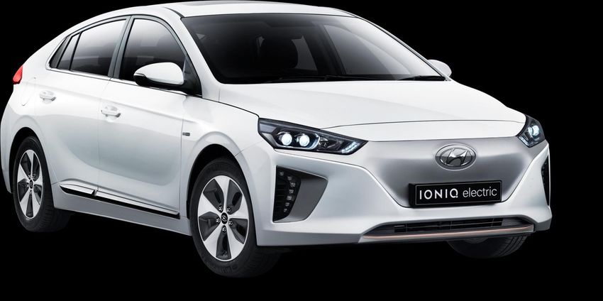
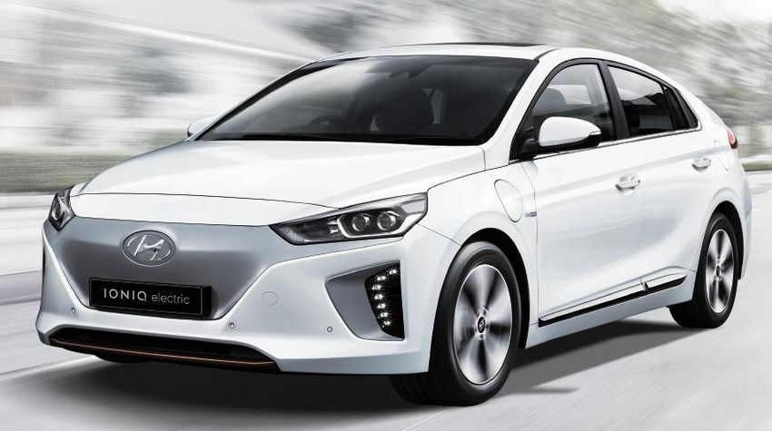
Identifying a Hyundai electric vehicle
Electric badge on Trunk and Blue Drive badge on side of Vehicle
The Hyundai IONIQ electric can be easily identified by the ‘electric ’ and the ‘IONIQ’ badge located
on the trunk lid and the ‘BLUE-DRIVE’ badge on the left side of the vehicle.
Electrocution Risk
Badging can become hidden after a crash due to damage to the vehicle. Always be sure to utilize
additional methods if identification before determining there is no badge present.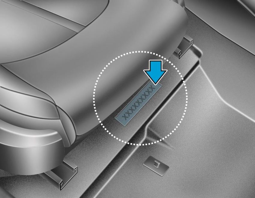
IONIQ electric Identification                                                                          3

VIN number

The Vehicle Identification Number (VIN) identifies the Electric Vehicle with a “H” displayed in the
8th position, as shown in the below drawing.

The VIN is punched on the floor under the passenger seat. The letter H in the 8th character of the
VIN indicates that it is an electric vehicle with battery [LiPB 360 V, 78 Ah] + Motor [3-phase AC 88
kw].

             XXXXXXXHXXXXXXX
                                    8th digit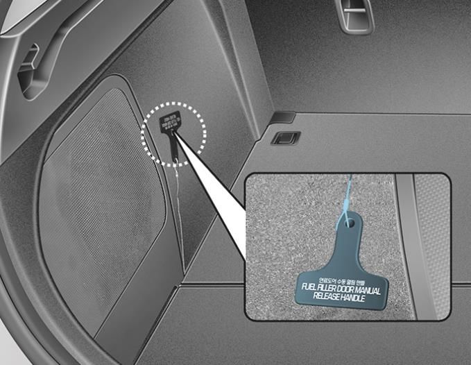
IONIQ electric Identification                     4

Motor Compartment

The IONIQ electric has a plastic power electric
cover with “EV” clearly shown on it.

Additionally, there are orange colored high-
voltage electrical cables in the motor
compartment.

Vehicle Underside

An orange colored cable covered by the under
cover is also visible on the underside of the
vehicle. This cable runs from the rear of the
vehicle to the motor compartment.
IONIQ electric Identification 5
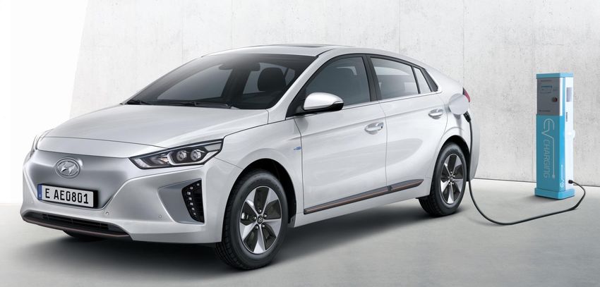
Charging Port
The Charging Port is located on the rear fender covered by the charging port cap and it has one
port for AC normal, fast and trickle charging.
How to open the charging port
1. Depress the brake pedal and apply the parking
brake.
2. Turn OFF all switches, shift to P (Park), and
turn OFF the vehicle.
3. Press the charging door open switch to open
the charging door. Charging door open switch
can be operated only when vehicle is turned
off.
4. Open the charging inlet cover (1).
Unlock Charging Door in Emergency
If the charging door does not open due to battery
discharge and failure of the electric wires, open
the tailgate and slightly pull the emergency cable
as shown left. The charging door will then open.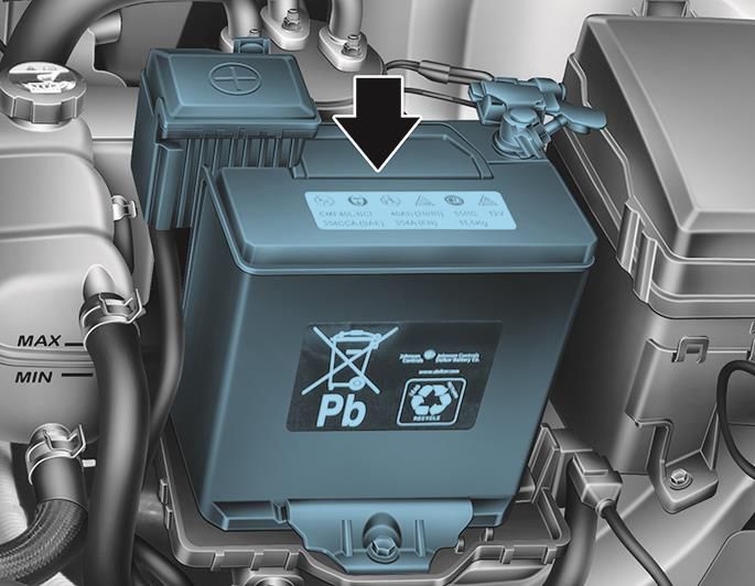
IONIQ electric Identification                                                                          6

 Electric Vehicle Cluster Instrument Panel

The Electric Vehicle Instrument Cluster Panel displays the electric vehicle specific features that
identify the IONIQ as a electric vehicle.

                   : Regeneration brake                2              : SOC(high voltage battery)
 1
                    /ECO/power gauge                                  Indicator indicates the charge
                                                                      state of the high voltage
                                                                      battery.

 3                 : The “Ready” Light indicates
                   the vehicle is ready for driving.

 1                                                                                   2

                             3

Charge Status Indicator

The battery charge status indicator, visible from
outside, at the center of the crash-pad, is
illuminated when the vehicle is charging.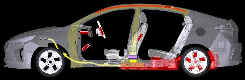
IONIQ electric main systems                                                      7

Key Specifications

                       Item                                  Electric

                                                  Permanent Magnet Synchronous
                                    Type
                                                             Motor

         Motor                Max. Output (kW)                 88

                              Max Torque (Nm)                 295

                         Maximum permissible
                                                              285
                             torque (Nm)
    Reduction Gear
                                 Gear Ratio                    7.4

           Inverter           Input Voltage(V)             240 ~ 413V
  EPCU
             LDC              Max. Output (kW)                 1.8

                              Max. Output (kW)                 6.6
         OBC
  (On Board Charger)
                               Output density
                                                              0.57
                                 (kVA/ℓ)

                                    Type               Lithium-ion polymer

                              Rated Voltage (V)               360

     High Voltage              Capacity (Ah) /
                                                             78 / 28
       Battery                  Energy (kwh)

                              Number for Packs
                                                       96CELL / 12MODULE
                               (Cell / Module)

                                Weight (kg)                   271.8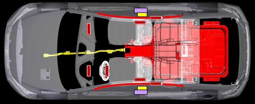
IONIQ electric main systems                                                                    8

     Vehicle Components Location

On Board Charger (OBC)     EPCU     High-Voltage Cable

  Electric Drive Motor     Reduction Gear                       High-Voltage Battery Assembly

            High-voltage          It supplies electricity from battery to the inverter, LDC, air
            Junction box          conditioner compressor, etc...
                                  On-Board Charger:
                 OBC
                                  Battery charging equipment (AC→DC)
                                  Electric Power Control Unit
                EPCU
                                  (Inverter + LDC + VCU)
                                  Low Power DC-DC Converter:
                 LDC
                                  Charge 12V supplementary battery
                                  DC → AC (from battery to traction motor)
               Inverter
                                  AC → DC (charge using regenerative braking)
                                  When current flows through the coil, it generates a
                Motor
                                  rotating magnetic field and generates motor torque.
                                  Increases Motor Torque and increased Torque is
          Reduction Gear
                                  transferred to the wheels.
                                  Supplies electric energy to traction motor and stores
       High voltage battery
                                  generated electric energy.
IONIQ electric main systems 9 Vehicle Components 12V Auxiliary Battery The 12V auxiliary battery is located on the drivers side of the motor compartment, and powers all of the vehicle’s standard electronics like radio, air conditioner, etc. Also, it powers the EPCU (Electric Power Control Unit) which controls high voltage current to main electronic systems like the motor and high voltage junction box. High-Voltage (HV) Battery The Lithium-ion Polymer HV battery contains a gel electrolyte and is made up of 96 - 3.75V cells wired in series for a nominal voltage of 360V with 78 Ah of capacity. The battery is located below the underbody. OBC (On-Board Charger) The OBC is the battery charging equipment that converts external AC to DC to charge the high voltage battery.
IONIQ electric main systems                        10

Electric Power Control Unit (EPCU)

The EPCU includes an Inverter, LDC (Low Power
DC-DC Converter) and VCU in one housing. The
inverter converts DC to AC to supply electricity
to the motor.

It also converts AC to DC to charge the high
voltage battery. The LDC converts high voltage
electricity to 12 volts to charge the 12V
auxiliary battery.

Electric Drive Motor

Mounted at the gear reduction unit, the Electric
Drive Motor is used for vehicle propulsion.
During deceleration or braking, it acts as an
alternator and charges the HV battery by
converting the vehicle’s kinetic energy into
electrical energy.

Gear Reduction Unit

The Gear Reduction Unit increases Motor
Torque and transfers increased Torque to the
wheels with Max. torque of 285Nm.
IONIQ electric main systems                                                                          11

High-Voltage Cabling

The high-voltage cabling in the IONIQ electric is
orange per the SAE standard. These cables run
from the rear of the vehicle where they connect
to the HV battery up to the front of the vehicle
where they connect to the Electric Drive Motor
and other HV components.

                     Electrocution Risk!

 • Never cut or disconnect the high voltage orange cabling and connectors without first disabling the
    system by removing the Service Disconnect Plug .
 • Exposed cables or wires may be visible inside or outside the vehicle. Never touch the wires, cables,
    connecters, or any electric components before disabling the system, to prevent injury or death
    due to electrical shock.
 Failure to follow these instructions can lead to death by electrical shock.
IONIQ electric main systems 12
High-Voltage Electrical Isolation
Unlike the 12V electrical system that is grounded to the vehicle’s chassis, the IONIQ electric’s high-
voltage electrical system is designed to be isolated from the vehicle.
Regulation of High-Voltage Electrical Current
Current from the High-Voltage Battery is
controlled by the Power Relay Assembly
(PRA), which consists of Positive and
Negative Main Relays, a Pre-charge Relay,
Pre-charge Resistor, and the Battery Current
Sensor. The PRA is mounted front side of the
High-Voltage Battery Pack Assembly and
controls the high-voltage power circuit
between the High-Voltage Battery and the
Electric Power Control Unit.
PRA
High-Voltage Safety System
There are multiple safety systems
incorporated into the IONIQ electric. The
system that protects the High-Voltage
Electrical System is called the Battery
Management System (BMS). The BMS is
located inside the Power Relay Assembly and
measures several parameters to maintain the
optimal performance of the High-Voltage
Battery. It controls the battery cooling fan to
ensure proper battery operation. In addition,
if a system fault occurs, the BMS turns off
the PRA to protect the system.
BMSIONIQ electric main systems 13
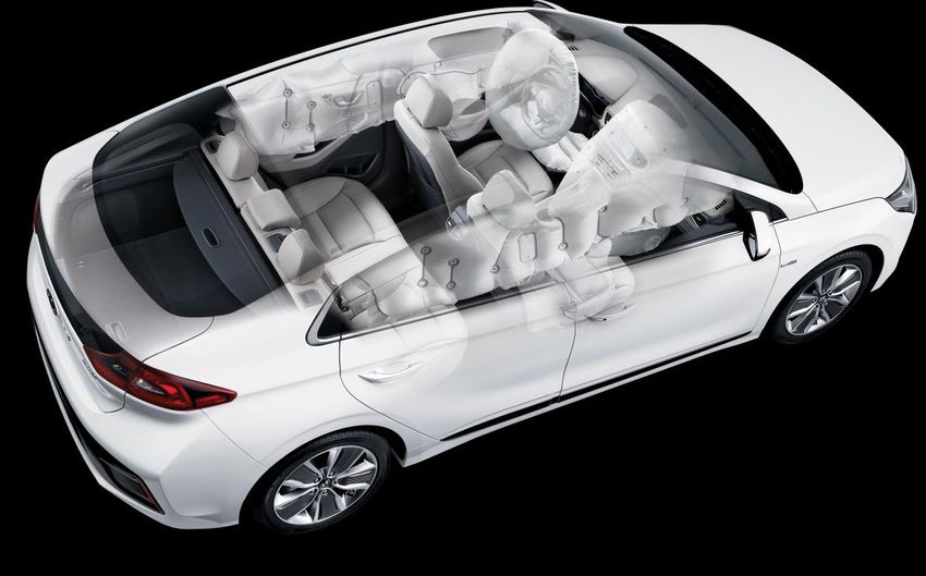
Airbag system (SRS : Supplemental Restraint System)
Airbag
Seven airbags are installed in the IONIQ electric as shown below. Before starting any emergency
procedure, make sure the vehicle ignition is turned off, disconnect the negative cable from the 12V
auxiliary battery to prevent accidental deployment of airbags.
* The actual air bags and seats in the vehicle may differ from the illustration
Number Name Location
1 Driver’s front airbag Driver side
2 Passenger’s front airbag Passenger side
3, 4 Side airbag Driver / Passenger side
5, 6 Curtain airbag Driver / Passenger side
7 Knee airbag Driver sideIONIQ electric main systems 14
Seat Belt Pretensioners
The IONIQ electric is equipped with seat belts with pretensioners. When the seat belt pretensioners
are activated in a collision, a loud noise may be heard and fine dust, which may appear to be smoke,
may be visible in the passenger compartment. These are normal operating conditions and are not
hazardous. The seat belt pretensioner assembly mechanisms may become hot during activation, and
may need several minutes to cool after they have been activated.
Sensors and Control Module
The airbags and pretensioners are managed by the SRS Control Module, or SRSCM, which is located
below the front of the center console. In addition, there are four side impact sensors : two
conventional accelerometer sensors in the B-pillars, and two pressure sensing sensors inside of the
front door modules. Their locations are illustrated in the image below.
1. Steering Wheel
2. Clock Spring
3. Front Seat Belt Pretensioner (FBPT)
4. Side Impact Sensor (SIS)
5. Front Impact Sensor (FIS)
6. Pressure Side Impact Sensor (PSIS)
7. Supplemental Restraint System Control
Module (SRSCM)
8. Airbag Warning Lamp
9. Emergency Fastening Device (EFD)
• Do not cut through any component.
• SRS components may remain powered and active for up to 3 minutes after the 12V electrical
system is shut off or disabled. Disconnect the battery negative cable and wait for at least 3
minutes before beginning work.
Failure to follow any of these instructions may result in serious injury or death from accidental
deployment of the airbag system.Emergency procedures 15 Initial Response: The following procedures should be used whenever you are dealing with a IONIQ electric at an emergency scene. All other operations should be consistent with your department’s standard operating procedures or guides. Electric vehicles damaged by a crash may have compromised high voltage safety systems and present a potential high voltage electrical shock hazard. Exercise caution and wear appropriate personal protective equipment (PPE) safety gear, including high voltage safety gloves and boots. Remove all metallic jewelry, including watches and rings. Identify When dealing with a IONIQ at the scene of an accident, emergency responders should always assume that it is a electric model until it can be proven otherwise using the identification features outlined in this ERG. External badging will usually be the first clue but it can often be hidden by damage caused in a crash. Always be sure to inspect multiple sides of the vehicle as well as using the clues found under the hood and in the interior of the vehicle.
Emergency procedures                                                                                   16

Immobilize

The next step is to immobilize the vehicle to prevent any accidental movement that can endanger
the emergency response personnel and any crash victims. Since the IONIQ electric doesn’t have an
engine, there will be instances where the vehicle appears to be off because of the absence of
engine noise. When in its “ready” mode, the vehicle can move almost silently using the electric
motor. Responders should approach the vehicle from the sides and stay away from the front or
rear as they are both potential paths of travel. Instructions for immobilizing the vehicle are shown
below.

    Chock the Wheels                  Engage Parking Brake                   Shift to park (P)
                                                                                 position
Emergency procedures 17
Disable
The final step in the initial response process, conducted after the vehicle is secured to prevent
movement, is to disable the vehicle, its SRS components and the high voltage electrical system. To
prevent current flow through the system, use one of the following procedures to disable the
vehicle.
Ⅰ. Disabling the system – Smart Key System and “POWER” START/STOP BUTTON
1. Check the status of the READY light on
the instrument panel. If the READY light is
illuminated, the vehicle is on.
(Refer to page 6)
a) If the READY light is NOT illuminated,
the vehicle is off, Do not push the
“POWER” START/STOP button because
the vehicle may restart.
b) To turn off the system, put the shift
“POWER” START/STOP Button
lever in the P (Park) position and press
the POWER button beside a shift lever.
Without depressing the brake pedal
Pressing
Button Position Vehicle condition
POWER button
OFF Off
One time ACC Electrical accessories are operational.
The warning lights can be checked before
Two times ON
the vehicle is started.
Three times OFF Off
Depressing the brake pedal while a shift lever is in the P (Park) position
Pressing
Button Position Vehicle condition
POWER button
OFF Off
One time - Ready to driveEmergency procedures 18
2. Before disconnecting the 12V battery, move the
smart key at least 2 meters away from the vehicle
to prevent accidental restart.
Smart Key
3. Disconnect the negative (-) 12V battery cable (A),
A
located in the motor compartment, to further
prevent the risk of accidental restart.
NOTICE
If necessary, lower the windows, unlock the
doors and open the trunk as required, before
disconnecting the 12V battery. Once the 12V
battery is disconnected, power controls will not
operate.
4. Use the following procedure to remove the Service Disconnect Plug and disable the high voltage
battery:
a) Remove the Service Disconnect Plug cover
(A) located in the trunk.
b) Remove the Service Disconnect Plug using
the following procedure :
①: Unlock → ②, ③: Release → ④: RemoveEmergency procedures 19
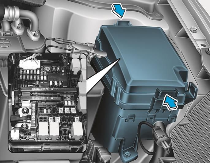
Ⅱ. Disabling the system – IG Relay Removal (Alternate Method)
1. Open the hood.
2. Remove the motor compartment
fuse box cover.
3. In the event the vehicle cannot be
disabled using the “Power”
START/STOP Button, pull the IG1,
IG2 fuses or relays from the motor
compartment room fuse box. If the
IG fuses cannot be located, pull out
all the fuses and relays in the fuse
box.
motor compartment fuse box
4. Disconnect the negative (-) 12V
battery cable (A), located in the A
motor compartment, to further
prevent the risk of accidental restart.
NOTICE
If necessary, lower the windows, unlock the
doors and open the trunk as required, before
disconnecting the 12V battery. Once the 12V
battery is disconnected, power controls will not
operate.Emergency procedures 20
5. Use the following procedure to remove the Service Disconnect Plug and disable the high voltage
battery:
a) Remove the Service Disconnect Plug cover
(A) located in the trunk.
b) Remove the Service Disconnect Plug using
the following procedure :
①: Unlock → ②, ③: Release → ④: Remove
If both methods of disabling system are unsuccessful, the vehicle is not secured from accidental
deployment of airbags and electric shock from high-voltage components.
Electrocution Risk!
• Before engaging in emergency response procedures, ensure the vehicle is disabled and wait for
more than 5 minutes to allow the capacitor in the high voltage system to discharge to avoid
electrocution.
• Exposed cables or wires may be visible inside or outside the vehicle. To prevent injury or death
due to electrical shock, never touch the wires or cables before disabling the system, to prevent
injury or death due to electrical shock.
Failure to follow any of these instructions may result in serious injury or death by electrocution.
Explosive Risk!
• Do not cut through any component.
• SRS components may remain powered and active for up to 3 minutes after the 12V electrical
system is shut off or disabled. Disconnect the battery negative cable and wait for at least 3
minutes before beginning work.
Failure to follow any of these instructions may result in serious injury or death from accidental
deployment of the airbag system.Emergency procedures 21 Extrication Operations The extrication operations for the IONIQ electric are similar to the conventional vehicle. However, the first responder should pay special attention when they extract occupants in the vehicle. Before extrication operations, the first responders should carry out “Initial Response: Identify, Immobilize and Disable” procedure section in page 16 to 20. Vehicle Stabilization Use standard stabilization (cribbing) points, as shown. Always be sure to connect to a structural member of the vehicle and avoid placing cribbing under high voltage cables, fuel lines and other areas not normally considered acceptable.
Emergency procedures                                                                               22

Extrication tools and procedure

When responding to an incident involving an IONIQ electric, we recommend that the first
responders follow their organization’s standard operating procedures for assessing and dealing
with vehicle emergencies. When the first responders cut the vehicle, they should always pay special
attention to airbag system, orange colored high voltage cables and other high voltage components
to avoid damage to parts which may increase the risks of explosion.

                            High-Voltage Cable

                                                 High-Voltage Battery Assembly

                   Airbag & Gas inflator                       EFD (Emergency Fastening Device)

                   Airbag                                      Airbag module

                   Gas inflator                                12V battery

                   Belt pre-tensioner                          Ultra (hot stamping) steel
Emergency procedures 23 Submersion Some emergency responses can involve a submerged vehicle. A IONIQ electric that is submerged does not have high-voltage component on the vehicle’s body or framework. It is safe to touch the vehicle’s body or framework if there is no severe damage to the vehicle, whether it is in water or on land. In the event the vehicle is submerged or partially submerged, remove the vehicle from the water before attempting to disable the vehicle. Drain the water from the vehicle. Use one of the methods described in sections of page 16 to 20 to disable the vehicle. • If severe damage causes high-voltage components to become exposed, responders should take appropriate precautions and wear appropriate insulated personal protective equipment. • Do not attempt to remove a Service Disconnect Plug while in the water Failure to follow any of these instructions may result in serious injury or death by electrocution.
Emergency procedures                                                                                       24

Vehicle Fire
After Initial Emergency Response Procedures have been applied, Firefighting Procedures may begin.
Hyundai recommends that each response team follow their own department’s standard operating
procedures for fighting vehicle fires in combination with the IONIQ electric specific details that are
covered in this section.

Firefighting Operations

If the high-voltage battery pack is either involved in or at risk of being involved in a fire in a IONIQ
electric, strict cautions must be taken while conducting firefighting operations due to following
reasons:

• Lithium-ion Polymer batteries contain gel electrolyte that can vent, ignite, and produce sparks
  when subjected to temperatures above 300°F.

• May burn rapidly with a flare-burning effect.

• Even after the high-voltage battery fire appears to have been extinguished, renewed or delayed
  fire can occur.

 - Use a thermal imaging camera to ensure the high voltage battery is completely cooled before

   leaving the incident.

 - Always advise second responders that there is a risk of the battery re-igniting.

 - Fire, submersion or a collision that has compromised the high voltage battery, always store it

   in an open area with no exposures within 50 feet.

• A burning battery could release hydrogen fluoride, carbon monoxide, and carbon dioxide
  gasses. Use NIOSH/MSHA approved full-face self-contained breathing apparatus (SCBA) with
  full protective gear.

Even if the high-voltage battery pack is not directly involved in a vehicle fire, approach the vehicle
very carefully.

Extinguishers

• Small fires that high voltage battery is not involved : Extinguish fires using a ABC extinguisher
  for an electric fire.

• Fires that the high voltage battery is involved or the high voltage battery is heating : Extinguish
  fires using large and sustained amount of water to cool the high voltage battery. Do not
  extinguish fire with a small amount of water. Firefighters should not hesitate to pour large
  amounts of water on the vehicle.
Emergency procedures                                                                                       25

High-Voltage Battery Damage and Fluid Leaks
The HV Battery assembly is enclosed in a sturdy metal case that is rigidly mounted to structural
components of the vehicle. This construction helps prevent damage to the HV Battery assembly
even in severe crashes. This section provides emergency responders with information regarding
how to mitigate the severity of a damaged HV Battery assembly or gel electrolyte spill, however
unlikely that might be.

• Cease all smoke, spark, flame activity around the vehicle.

• Electrolyte solution is a skin irritant.

• Do not touch or step on the spilled electrolyte.

• If electrolyte leak occurs, wear appropriate solvent resistant PPE and use oil, sand, or a dry cloth
   to clean up the spilled electrolyte. Be sure to adequately ventilate the area.

                    Irritant Substance Risk!

• Internal components of HV Batteries are irritants and sensitizers.
• To avoid contact with these irritants and sensitizers wear positive pressure self- contained
  breathing apparatus (SCBA) and other personal protective equipment (PPE) designed for use with
  these types of hazards.

Failure to wear proper SCBA and PPE can result in serious injury or death

• Electrolyte solution is an eye irritant – If contact with eyes, rinse with plenty of water for 15
   minutes.

• Electrolyte solution is a skin irritant. Therefore, if there is contact with skin, wash off with soap.

• Electrolyte liquid or fumes that have come into contact with water vapors in the air will create an
   oxidized substance. This substance may irritate skin and eyes. In these cases, rinse with plenty
   of water and see a doctor immediately.

• Electrolyte fumes (when inhaled) can cause respiratory irritation and acute intoxication

Move to a well ventilated location for fresh air and wash mouth with water. See a doctor
immediately.
Roadside Assistance 26 Towing When towing IONIQ electric vehicle, all wheels should be off the ground and not in contact with the road. If emergency towing is necessary, we recommend having it done by an authorized Hyundai dealer or a commercial tow-truck service. The use of wheel dollies or flatbed is recommended. • Do not tow the vehicle backwards with the front wheels on the ground as this may cause damage to the vehicle. • Do not tow with sling-type equipment. Use wheel lift or flatbed equipment. • Never tow the vehicle with the front wheels on the ground (forward or backward), as this may cause damage to the vehicle.
Roadside Assistance                                                                                  27

To Jump Start the Car

1. Make sure the booster battery is 12-volt.

2. If the booster battery is in another vehicle, do not
allow the vehicles to touch.

3. Turn off all unnecessary electrical loads.

4. First connect one end of a jumper cable to the
positive terminal of the discharged battery in the
motor compartment, then connect the other end to
the positive terminal on the booster battery.

Proceed to connect one end of the other jumper cable to the negative terminal of the booster
battery, then the other end to a solid, stationary, metallic point away from the battery (for example,
the hood latch).

• Do not connect the cables to or near any part that moves when the vehicle is started.
• Do not allow the jumper cables to contact anything except the correct battery terminals or the
  correct ground.

• Do not lean over the battery when making connections.

5. Start the vehicle with the booster battery, then start the vehicle with the discharged battery.

6. After a few minutes, turn off both of the vehicles.
7. Remove the negative terminal cable first, and then remove the positive terminal cable. If the

  cause of your battery discharging is not apparent, we recommend that the system be

  checked by an authorized HYUNDAI dealer.
Ⓒ2016 Hyundai Motor Company
                                 All rights reserved.
This document may not be altered without the written
             permission of Hyundai Motor Company.
You can also read