Efficiency Evaluation of Processed Photogrammetric Data Captured by GPS Digital Camera
←
→
Page content transcription
If your browser does not render page correctly, please read the page content below
World Applied Sciences Journal 8 (4): 414-421, 2010
ISSN 1818-4952
© IDOSI Publications, 2010

                         Efficiency Evaluation of Processed Photogrammetric
                                Data Captured by GPS Digital Camera

                                       Ayman F. Ragab and Ahmed E. Ragheb

           Department of Public Works, Faculty of Engineering, Ain Shams University, Cairo, Egypt

    Abstract: Recent developments in the acquisition and processing of close range images is an aim of primary
    importance in photogrammetry and computer vision, for digital documentation and reconstruction of objects
    featuring different characteristics. This demand is increasing in various fields, such as Cultural Heritage,
    Computer Graphics, Robotic and many other. For this reason, the digital image–based technique has been
    extensively used to produce high quality 3D models of heritage sites and historical buildings for documentation
    and preservation purposes. The features of any 3D model are highly dependant on the use of that model and
    can be very variable in term of accuracy and time for their creation. In the current paper, a certain digital
    measuring scheme based on a GPS-enabled digital camera (RICOH Capilo 500SE) is thoroughly tested and
    investigated for its capability in 3D modeling, as a complementary research in the same field. A practical field
    experiment showed a positional accuracy reported by this system was about 0.42 m in the 3D coordinates of
    some selected object points on a photographed façade captured by this camera. This accuracy is optimistic
    since the taken images were processed with only one control point, as a saving tool in time and cost of data
    acquisition. Moreover, this digital system can be used as a Mobile Mapping System MMS in some applications
    under certain circumstances and precautions. As an overall evaluation, this combined digital system should
    be subjected to more researches for the time being and further modifications and enhancements in the future.

    Key words: Close range photogrammetry         Heritage documentation          GPS    Digital camera

                   INTRODUCTION                                          Digital documentation of cultural heritage sites and
                                                                    objects is becoming a very important field of applications
     Accurate surveying for data acquisition and                    for 3D modeling and reconstruction. Consequently, digital
processing is a key factor for cultural heritage                    photogrammetry is one of the most rapidly developed,
preservation and valorization, particularly on complex              cheap and easy phenomena that uses recent digital
objects or when the 3D model requires different levels of           cameras with great storage capacity and digital
details. So, any adopted survey must be capable to                  photogrammetric measuring approaches. In this context,
produce        an accurate geometric and qualitative                close range digital images along with the considerable
description of the current situation of the structure in            improvements in photogrammetric software can be
the shortest time [1]. In this field, there is no single            considered as the most commonly used input data for
technique that can be considered the best for all 3D                reconstructing building facades automatically or semi-
modeling applications to give satisfactory results in all           automatically with excellent precision [4, 5]. The accuracy
situations, concerning high geometric accuracy,                     and/or realistic level of the building façade models are
portability, automation, photorealism and low costs,                vital for documenting and reconstructing the historical
since available techniques vary in accuracy, reliability,           and cultural heritage buildings. Accordingly, the correct
ability to capture details and their level of automation.           interpretation of images showing building scenes is a
Therefore and despite of the potential of each single               challenging task, due to the complexity of the scenes and
technique, it is often very useful to combine data obtained         the great variety of building structures and details [6].
from different technologies, in order to get the optimum                 Moreover, another special challenge, which is more
benefits and ensure the correctness of modeling complex             important than that occurring in photogrammetry, was
structures [2, 3].                                                  achieved in the field of spatial data collection through

Corresponding Author: Ayman F. Ragab, Department of Public Works, Faculty of Engineering, Ain Shams University, Cairo,
                      Egypt
                                                              414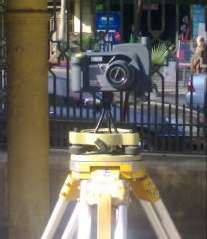
World Appl. Sci. J., 8 (4): 414-421, 2010

the use of satellite systems [7]. In this case, Global
Positioning System (GPS) comes into use even in
terrestrial photogrammetry especially in architectural and
archeological photogrammetric studies and works to
perform the absolute geo-referencing of the area and the
description of the structure. Thus, in accordance with
digital photogrammetry principles, GPS can determine
the perspective center's coordinates of the used digital
camera mounted few decimeters above the ground on a                Fig. 1: Used RICOH Capilo 500SE GPS digital camera
tripod. Consequently, this combined digital close range                    http://www.korecgroup.com/images/images_img-
photogrammetric system incorporates real time location                     229.jpg
information and map information, which saves time and
creates economic efficiency [8], since in most cases real          nearest place required of the indoor exposure station
time reconstruction is necessary. This is done by                  and then shoot images indoors using the pre-saved
minimizing needed ground control due to the decrease in            GPS information. This of course could be very handy,
number of unknowns through the use of a GPS digital                especially in Monumentation and documentation of
camera providing the coordinates of the exposure station.          buildings’ façade in closed area with no GPS satellite
                                                                   coverage.
     Accordingly, the main purpose of the current study
                                                                        For evaluation purposes, two kinds of GPS receivers
is to test the efficiency of a new combined digital close
                                                                   are used, the first is a Trimble R3 precise GPS geodetic
range photogrammetric system (digital camera equipped
                                                                   receiver used for referencing of precise coordinates,
with GPS), as an auxiliary measurement and mapping tool,
                                                                   while the other is a Garmin Venture GPS navigator used
for documenting a building façade to be reconstructed in
                                                                   for the assessment of the used technique. In addition, a
a 3D model. To achieve this purpose, the description of
                                                                   Topcon 712 GTS total station was also used for the
the used instruments as well as the photographed façade
                                                                   survey of the chosen points precisely relative to a local
along with the main characteristics of the used combined           coordinate system.
digital system is outlined first. This includes the chosen
GPS control points, object points and acquisition of               The Photographed Facade: In order to achieve the
digital images. Then, the criteria of assessment for               sought objective of the current study and demonstrate
evaluating the obtained results is presented and analyzed.         the potential of such system, a certain field experiment
Finally, the output main conclusions along with some               has to be designed for this purpose. Since the core of
appropriate recommendations will be given.                         this study concentrates on documenting building facades
                                                                   accurately and economically, which encompasses several
  DESCRIPTION OF THE FIELD EXPERIMENT                              geometrical details using close range photogrammetry, the
                                                                   test field area was chosen to be the architectural frontal of
     A brief on the different instruments used in the              the main building of the faculty of Engineering of Ain
current research is outlined first, followed by a brief on         Shams University. This façade, whose captured image will
the field experiments including the needed ground control          be presented later in this section, has many architectural
system and the used image configuration and                        features like windows, doors, columns, stone blocks
specifications, in addition to the data processing                 interlock and arches with a variety of geometric details
technique.                                                         that will nearly suffice our requirements here.
                                                                         Since these existing features have to be modeled
Used Instruments and Techniques: The main device                   accurately as a three-dimensional (3D) presentation for
used here is a stand alone digital camera equipped with            documentation purposes, this implies the choice of well
a GPS receiver, namely, RICOH Capilo 500SE GPS                     defined sharp object points, well distributed over this
camera shown in Figure 1. This RICOH Capilo camera -               selected area to be photographed and also should be
GPS camera - here after, has a solid state CCD (Charged            sufficient in number for any further computations and
Coupled Device) image sensor of 8.0 Megapixels. It is              analysis. Figure 2 shows a sketch drawing for an
available with an integrated GPS receiver and a digital            elevation view of this investigated façade along with the
compass. A very useful capability of this camera is that           chosen fourteen (14) object points. This elevation view
the latest GPS information is retained in the camera for           was drawn without any calculations or measurements
ten minutes whether logged or not on GPS satellites.               to represent its general layout, just to illustrate the
This enables to acquire GPS information outdoors in the            distribution of all selected target object points within this

                                                             415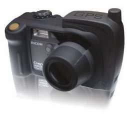
World Appl. Sci. J., 8 (4): 414-421, 2010

Fig. 2: Elevation view of the used building façade along            Fig. 3: General layout of the GPS ground control points
        with the chosen test points                                         and location of the three different camera stations

photographed façade. These object points will serve as              points appear in each photo taken by the camera at
both control and check points.                                      each station, besides the three GPS base stations, as
                                                                    clearly depicted in one of the taken images presented in
The GPS Control Points: The field procedure here in                 Figure 4. The GPS coordinates of the exposure station
requires the availability of some kind of ground control            position are automatically determined when the camera is
points to be used later as reference in the documentation           switched on. The compass can automatically capture the
survey of the photogrammetric approach, for assessment              direction and the horizontal tilt angle in which the picture
of the current investigation, as well as other terrestrial          was taken. Accordingly, by integrating both the GPS
points to act as exposure stations of the used camera.              device and the compass directly into the camera, this
Therefore, three ground control points are chosen namely            combined digital system covers the whole working
S1, S2, S3, where as their ground coordinates were                  process from position localization, over image acquisition
computed by precise and adjusted GPS observations to                to data transfer and store information about the position
act as check points in order to compare the newly used              and the direction in the EXIF header of the picture. In
approach with the traditional technique requiring the               addition, the attached GPS PhotoMapper software
availability of ground control. These points constitute the         enables the connection of photos with their location
reference system by which the coordinates of the other 14           and the integration into a Geographic Information
object points placed on the façade were determined by               System (GIS). This software allows the utilization of the
total station observations. In addition, three stations             saved information to be integrated into the geographic
named S4, S5 and S6 are chosen as exposure stations for             information system ArcGIS from ESRI where the photos
the used GPS camera. The location of all these -                    can easily be administered by the GIS user. Additional
previously mentioned - six points is chosen in an                   information on this state-of-the-art camera and detailed
open area to ensure high GPS coverage with a low                    specifications can be found in www.ricoh.com.
mask angle as well as to be least affected by                            Shortly, many advantages are gained such as:
multipath. Figure 3 shows a layout of the location of all           Selection criteria are offered during the loading process
chosen GPS control points as well as the three exposure             of the photos into ArcGIS, e.g. the date or time the photos
stations.                                                           were taken. Thus, long and frustrating searching
                                                                    procedures in archives belong to the past are eliminated.
Acquisition of Digital Images: The selected building                Ability to control disasters since the situation is
facade was captured from the three exposure stations                recorded with exact time and position information. Finally,
varying in both scale and orientation, as indicated                 it is useful in classical object documentation and
previously in Figure 3. These exposure stations were                administration activities since long working hours in the
placed in such a way that nearly all chosen target object           office for georeferencing captured images has been saved

                                                              416
World Appl. Sci. J., 8 (4): 414-421, 2010
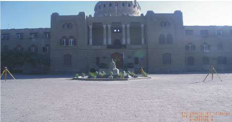
Fig. 4: Digital photo taken at one of the exposure stations
context, minimum of three ground control points should
be located in the overlapped area to orient any stereo-pair.
If the object is visible on three or more images, bundle
adjustment solution is possible including all available
measurements at the same time [9]. Preserving the final
accuracy of the bundle solution with decreasing the
number of required control points is a challenging task in
terrestrial photogrammetry, which can be the main core
and goal of the current research. In this terminology, the
absolute position of the mapped features can be
determined and evaluated by directly georeferencing the
camera station using the detachable GPS module with less
control points [10].
The 3D reconstruction process based on digital close
range photogrammetry can be divided mainly to
Fig. 5: Fixation of the GPS camera over the tripod orientation, measurements and modeling. So, automatic
reconstruction depends on the automation of these
because most data is collected automatically with the GPS procedures [11]. Hence, the Leica Photogrammetric Suite
camera and GPS PhotoMapper. It should be noted here (LPS) Ver. 9.3 is the used digital photogrammetric
that, the camera is held over a tripod during capturing the workstation for processing three captured images at S4,
images and fixed in such a way to control its position and S5 and S6 to extract 3D coordinates using the technique
orientation, as depicted in Figure 5. known as image correlation. It is a commercial software
module within the larger IMAGINE package distributed by
Photogrammetric Data Processing: Bundle adjustment Leica Geosystems, which has a collection of seamlessly
is the most appropriate method used in digital integrated tools providing accurate and production-
photogrammetery since it depends on analytical oriented photogrammetric output.
principals as well as being a numerical technique.
Colinearity condition, which depends on aligning the METHODOLOGY OF INVESTIGATION
points on object, perspective center of camera and on the
image of the object, is the algorithm that forms the In order to assess the accuracy of the used
mathematical model of the GPS supported terrestrial combined digital system for 3D reconstruction of a
photogrammetry. It relates both image coordinates system certain façade, it should be a referenced or relative to a
and GPS object coordinates system through the intrinsic datum for comparison. Accordingly, the 3D ground
and extrinsic orientation parameters of the camera. In this coordinates of the three base GPS ground control points
417World Appl. Sci. J., 8 (4): 414-421, 2010
S1, S2 and S3 and the placed object points, computed the images are scaled and oriented to the three geo-
from geodetic GPS receivers and total station respectively, referenced ground control points computed from
will be the base for such comparison. Hence, the precise and adjusted GPS observations. Table 1 lists the
corresponding computed 3D coordinates of the same statistical information of the output discrepancies in the
object points resulted from the processed images using 3D directions and the corresponding spatial positions for
the LPS software will be assessed related to these all 14 chosen object check points. This information
reference coordinates. To achieve the above-mentioned includes the RMS of such discrepancies as well as the
objectives of this current research, the digital bundle standard deviations (SD) of the computed 3D ground
solution will be carried out under two main study cases. coordinates. Note that the X-direction is taken parallel to
Both cases differ according to the treatment of the the building façade, Y-direction is perpendicular to the
extrinsic orientation parameters (exposure station building façade pointing towards the building, while the
coordinates and rotation angles) of the captured Z-direction points upwards.
images, in which the former case treats those parameters From this table, it is obvious that close range
as unknown values whereas the latter considers the photogrammetry (close range images captured by the
exposure stations coordinates are only known as fixed used camera and processed by digital software) is
values, taken from the GPS receiver embedded in the suitable and powerful in architecture and 3D building
camera. On the other hand, each case will be solved models, since its associated positional accuracy is in
twice according to the type of the involved control terms of few millimeters. It should be noted that and
points, whether they are GPS stations or placed object according to the methodology of investigation, another
points. bundle solution is carried out using three object points
In all study cases, two evaluation criteria have as control points, well distributed on the façade. A non-
been suggested to completely test the efficiency of this significant degradation in all discrepancies information is
digital system. The first criterion is concerned with the occurred, but still considered as promising values.
discrepancies at the selected object points, as they were
evaluated as the difference between the reference values GPS-Enabled Digital Camera: In this second case, the
and the corresponding computed ones from each bundle camera position and orientation at each observing station
solution. In this case, the principal statistical parameters was extracted from both attached GPS receiver unit and
of these discrepancies, namely the maximum, mean and digital compass. As stated before, the camera is held on
minimum as well as Root Mean Square (RMS), for single the tripod in such a way to control and fix the 3D
discrepancy determination will be evaluated. The second coordinates of all exposure stations, besides considering
criterion pertains to the structure of the output covariance the rotation angles are nearly the same at each exposure
matrix of the 3D coordinates of all object points. station. Accordingly, this leads to the possibility of
decreasing the required number of control points. In this
PRESENTATION AND ANALYSIS OF context, two different bundle solutions are investigated to
THE FIELD EXPERIMENTS RESULTS test the efficiency of the used GPS-enabled camera. The
first solution is performed with only two control points,
This section is devoted to the manipulation and once while fixing the 3D coordinates of all exposure
discussion of the results obtained from the solution of the stations obtained from the attached GPS receiver called
captured three images that include the tested façade along “Coordinate Fix” and the other while fixing the rotation
with all selected object points. Those images were taken angles at the three exposure stations, obtained from the
nearly 35.0 m away from the façade with the used camera camera’s compass called “Rotation Fix”. The second
zoomed to the standard focal length of 5.8mm. The LPS solution is performed with only one control points and
software was used twice to get the 3D coordinates of all fixed 3D coordinates of all exposure stations, as well as
object points, for previously-mentioned two cases of considering the rotation angles of one of the exposure
treating the extrinsic orientation parameters of exposure stations being also fixed. It should be noted that, this
stations. configuration of bundle solution was preferably selected,
since the errors of the rotation angles at each exposure
Stand-alone Digital Camera: In this initial experiment, the station have more influence on the final positional
entire measuring and processing scheme was carried out, accuracy than the corresponding errors in the exposure
where as the exposure stations’ orientation parameters of station coordinates [12], as will be verified also in this
the digital camera are completely unknown. In this case, practical field experiment.
418World Appl. Sci. J., 8 (4): 414-421, 2010
Table 1: Statistical Analysis of the Output Results of the Stand-Alone Digital Camera
Tested Direction RMS of Discrepancies (mm) SD of computed Ground Coordinates (mm)
X-direction (along the façade) 1.28 0.21
Y-direction (perpendicular to the facade) 2.74 0.46
Z-direction (vertical) 0.98 0.32
Spatial Position 3.18 -----
Table 2: Statistical Analysis of the Output Results of the GPS/Compass Digital Camera
Two Control Points
---------------------------------------------------
Statistical Parameters Coordinate Fix Rotation Fix One Control Point
Discrepancies (cm) X-direction Mean 12.6 16.9 18.0
RMS 14.2 18.6 19.7
Y-direction Mean 19.8 26.4 30.1
RMS 22.1 29.8 33.7
Z-direction Mean 8.5 12.1 12.8
RMS 10.5 13.4 14.9
Spatial Position Mean 26.7 34.5 38.7
RMS 28.3 37.6 41.8
SD of 3D Coordinates (cm) SDX 3.5 4.1 4.7
SDY 4.9 5.3 6.1
SDZ 2.7 2.9 3.0
Table 3: Ground Coordinates Discrepancies between Both Used Digital System and GPS Navigator Compared with the Precise GPS Observations
Discrepancies (m)
---------------------------------------------------------------------------------------------------------
Station Name Observation Method Latitude Longitude Altitude
S1 GPS Navigator 1.203 1.192 0.915
Used System 0.651 0.468 0.558
S2 GPS Navigator 1.547 2.202 0.923
Used System 0.873 0.782 0.514
S3 GPS Navigator 0.931 0.636 0.889
Used System 0.452 0.368 0.423
Table 2 shows the corresponding statistical one control point. These discrepancies are computed at
parameters of the object points’ resulted discrepancies each station as the difference between the references
in both bundle solutions. It indicates an expected coordinates from GPS precise observations and the
deterioration in the positional accuracy of the computed corresponding ones computed by using both the tested
coordinates, related to the precision of both GPS receiver combined digital system and the hand-held navigator.
and digital compass as well as the reduction of the Accordingly, the used digital combined system is better
involved number of control points. Analyzing these listed when compared to the navigator GPS observations,
results still gives attractive findings; since a positional concerning the smaller discrepancy values at each station.
accuracy of about 0.42 m was achieved using this Moreover, processing the images with fixed exposure
combined digital solution with only one control point in stations coordinates obtained from the attached GPS
the 3D modeling of the photographed façade. receiver exactly gives better results than considering the
Similarly, the same bundle solutions are performed corresponding coordinates as fixed values using the GPS
but with the other type of the object control points, which navigator.
are observed and computed by the total station as Finally and in order to make a concise efficiency
previous but with the other three. Also, nearly the same evaluation of the used combined digital system, another
positional accuracy deterioration occurred at the solution was run by the LPS without using any control
remaining object points. In addition, Table 3 indicates the points. In this case, all extrinsic orientation parameters
discrepancies at the three GPS stations when using only were taken directly form the information provided and
419World Appl. Sci. J., 8 (4): 414-421, 2010
displayed by the GPS receiver unit and the digital GPS receiver and mainly the digital compass in such a way
compass. The corresponding results give a positional to control the attitude of the camera at the exposure
accuracy as a RMS value of nearly 89.0 cm, which epoch. In addition, more research can be performed to
completely matched with those issued by Scarmana [10] investigate the influence of each displayed information
as 83.0 cm for processing only a stereo-pair with this concerning the attitude (each rotation angle) and position
system. Of course, the more images taken, the more (each component of the 3D ground coordinates) of
degradation in the positional accuracy, due to the fixation exposure stations on the final positional accuracy.
of all considered extrinsic orientation parameters. Hence,
this situation is not recommended in complex 3D modeling REFERENCES
but may be useful for other applications that require
timeless data acquisition and moderate positional 1. Bitelli, G., V.A. Girelli, M.A. Tini and L. Vittuari,
accuracy. 2005. Integration of Geomatic Techniques for
Quick and Rigorous Surveying of Cultural Heritage,
CONCLUSIONS CIPA XX International Symposium, 26 September –
01 October, Torino, Italy.
Based on the results obtained from the practical field 2. Guidi, G., F. Remondino, M. Russo, F. Minna and
experiment discussed in the present investigation, the A. Rizzi, 2008. 3D Modeling of Large and Complex
following conclusions are enumerated, along with some Site Using Multi-Sensor Integration and Multi-
recommendations: Resolution Data, The 9 th International Symposium on
Virtual Reality, Archeology and Cultural Heritage
Close range images processed by digital VAST.
photogrammetric software are suitable for 3D 3. Al-kheder, S., Y. Al-shawabkeh and N. Haala,
modeling of structures, due to its great improvements 2009. Developing a Documentation System for
in the positional accuracy as well as its versatility. Desert Palaces in Jordan Using 3D Laser Scanning
The used combined digital system is efficient to be and Digital Photogrammetry, J. Archaeol. Sci., 36:
implemented in many applications, such as 537-546.
architecture measurements and complex structures 4. Pu, S. and G. Vosselman, 2009. Refining Building
models, according to its final accuracy as 0.42 m, Façade Models with Images, IAPRS, Vol. XXXVII,
even in the case of using one control point while Part 3/W4, Paris, France.
processing three captured images. 5. Chiabrando, F., M.L. De Bernardi and S. Curetti, 2009.
As expected, errors in the attitude (rotation angles) “Integration of Low Cost Geomatic Technique to
values of any camera station given by the digital Support the Architectionical Project. The Perlo Castle
compass will affect greatly the final spatial Area Survey”, 22nd CIPA Symposium, Commission
positioning compared with the corresponding errors VI, WG VI/4, October 11-15, Kyoto, Japan.
given by the attached GPS unit. 6. Drauschke, M., R. Roscher, T. Labe and W. Forstner,
The used GPS-enabled camera (Ricoh 500SE) can be 2009. Improving Image Segmentation Using Multiple
considered as a Mobile Mapping System MMS, for View Analysis, IAPRS, Vol. XXXVII, Part 3/W4,
its capabilities compared with its cost and time in Paris, France.
data acquisition. 7. Corumluoglu, O., I. Kalayci, S. Durduran, C. Altuntas,
Processing the images captured by this camera I. Asri and A. Onal, 2004. GPS Virtual Station
without control points is not suitable for 3D Technique (GPSSIT) and its Challenge in Terrestrial
modeling, but can be used in applications that to Photogrammetric Applications, ISPRS Commission
somehow do not necessitate precise height III, WG V/4.
information such as Earth works. 8. Choi, H., C. Ahn, J. Kim and H. Han, 2008.
Development of positioning Information Realized
Hence, several challenges should be still considered Digital Close-Range Photogrammetric System, The
concerning the generalization and utilization of a GPS International Archives of the Photogrammetry,
enabled digital camera to be used widely as a Mobile Remote Sensing and Spatial Information Sciences,
Mapping System MMS. These challenges may include Commission V, WG-V-5, Vol. XXXVII, Part B5,
increasing the positional accuracy given by the attached Beijing, China.
420World Appl. Sci. J., 8 (4): 414-421, 2010
9. Girelli, V.A., M.A. Tini and A. Zanutta, 2005. 11. Zheng, J., W. Yuan and S. QingHong, 2008.
“Traditional and Unconventional Photogrammetric “Automatic Reconstruction for Small Archeology
Technique for Metrical Documentation of Cultural Based on Close-Range Photogrammetry”, The
Heritage: The Example of the Rolandino Dei International Archives of the Photogrammetry,
Passaggieri Tomb (ST. Domenico Square) Survey in Remote Sensing and Spatial Information Sciences,
Bologna”, CIPA XX International Symposium, Commission Wgs-PS, WG-V/1, Vol. XXXVII, Part B5,
October 01, Torino, Italy. Beijing, China.
10. Scarmana, S., 2009. An Accuracy Assessment of a 12. Ragab, A.F., 2005. The Influence of the Extrinsic
GPS-Enabled Digital Camera, International Global Orientation parameters of a Stereo-Pair on the
Navigation Satellite Systems Society, IGNSS Positional Accuracy of Object Points, The Scientific
Symposium, 1-3 December, Australia. Engineering Bulletin of the Faculty of Engineering,
Ain Shams University, Vol. 40, No. 3.
421You can also read