DTC Switching Strategy for Open-end Winding of Induction Machines Fed by a Dual-output Indirect Matrix Converter
←
→
Page content transcription
If your browser does not render page correctly, please read the page content below
186|Creative Commons Attribution b
         https://doi.org/10.3311/PPee.17597

Periodica Polytechnica Electrical Engineering and Computer Science, 65(3), pp. 186–195, 2021

DTC Switching Strategy for Open-end Winding of Induction
Machines Fed by a Dual-output Indirect Matrix Converter

Abdelkader Beladel1*, Abdellah Kouzou1, Mohamed Elbar1, Ahmed Hafaifa1

1
    Applied Automation and Industrial Diagnostics Laboratory (LAADI), Faculty of Sciences and Technology, Ziane Achour University,
    P. O. B. 3117, Djelfa 17000, Algeria
*
    Corresponding author, e-mail: a.beladel@mail.univ-djelfa.dz

Received: 28 November 2020, Accepted: 12 January 2021, Published online: 07 June 2021

Abstract
This paper deals with the Direct Torque Control (DTC) of Dual Indirect Matrix Converter (DIMC) feeding an open-end winding three-
phase Induction Motor (IM). Indeed, the open-end winding topology allows overcoming the main problem of Common-Mode Voltage
(CMV) which is responsible of presence of stresses in the motor winding in classical topologies, controlling separately the winding of
the three-phases, reducing the voltage stress of the power electronics switches and to decreasing the voltage and current harmonics in
each phase. The proposed Dual-output Indirect Matrix Converter generates 18 active voltage space vectors. Whereas, in the proposed
algorithm presented in this paper to ensure the control of the proposed topology it is implemented only with two null vectors and six
active voltage vectors for each output. It is based on same idea of the space vector pulse width modulation that is applied separately
for both converters to ensure the control of their output voltages. Indeed, to ensure the required voltage at each winding the output
voltage of the first matrix converter are generated normally and output voltage of the second matrix converter are generated with
180° phase shift. The obtained simulation results prove clearly the overall performance of the control of the studied drive system
based on the proposed topology and its control algorithm which may be extended to other drive system application, especially in
industrial application where more improved performances are required.
Keywords
Direct Torque Control (DTC), Open-End Winding Induction Motor (OEWIM), Indirect Matrix Converter (IMC), Common-Mode Voltage (CMV)

1 Introduction
Recently many topologies of have been proposed to ensure                allows obtaining a multi-level voltage at the terminal of
driving the three-phase Induction Motor (IM) and to pro-                each stator winding phase separately, thirdly the Common-
vide high performances compared to the well know con-                   Mode Voltage (CMV) is usually presenting a very delicate
ventional topologies. Among these topologies are the                    challenging problem in stator star connection fed by con-
multi-level topologies, which allow obtaining better out-               ventional inverter which induces shaft voltage leading to the
put voltage and current qualities that lead to better per-              circulation of bearing current causing to premature bearing
formance and high efficiency. However these topologies                  and motor failures over time. These problems can be solved
require a bulky DC link between the AC-DC converter and                 by using the OEWIM presented in this paper [1, 2].
the DC-AC converter similarly to the conventional ones.                    The Indirect Matrix Converter (IMC) is an AC-AC type
On the other side the circuit control are more complicated              converter. It is basically composed of a variety of bidirec-
and more components are required such as the clamped                    tional switches that are used to ensure the transfer of the
diodes, the flying capacitors or more separated number of               power supply to the load with controlled frequency and volt-
DC sources following the used multi-level topology. In this             age magnitude without using any DC connection or bulky
paper the Open-End Winding Induction Motor (OEWIM)                      energy storage components [3, 4]. Indeed, the absence of
powered by a dual AC-AC converter is presented, firstly the             large energy storage elements in the DC bus such as capac-
bulky DC link is removed as an Indirect Matrix Converter                itors is the first real preference of such topology over the
(IMC) is used, secondly the application of a dual IMC                   ordinary rectifier-inverter based topologies that have been

Cite this article as: Beladel, A., Kouzou, A., Elbar, M., Hafaifa, A. "DTC Switching Strategy for Open-end Winding of Induction Machines Fed
by a Dual-output Indirect Matrix Converter", Periodica Polytechnica Electrical Engineering and Computer Science, 65(3), pp. 186–195, 2021.
https://doi.org/10.3311/PPee.17597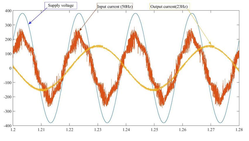
|187
                                                                                                                     Beladel et al.
                                                                Period. Polytech. Elec. Eng. Comp. Sci., 65(3), pp. 186–195, 2021

used along the last decades in most of the industrial appli-
cations. Hence this converter topology allows obtaining
less size and weight compared the conventional [3, 5, 6].
On the other side, the IMC can provide from the available
AC three-phase power supply, AC output voltages with
desired amplitude and frequency, theoretically with unlim-
ited number of output phases. Based on the control tech-
nique used, the harmonic content can be reduced in the out-
put side of the IMC, where the input power factor can be                        Fig. 1 Indirect Matrix Converter (IMC)
also improved [5–7]. However, the harmonics content in the
input side current is presenting a big challenge in the IMC
topology, where the simple solution to handle this issue can
be achieved by using an input LC filter as shown in Fig. 1.
   In this paper the IMC topology is used to power an
Open-End Winding Induction Motor (OEWIM) which can
be obtained by opening the neutral or the star point of the
stator windings of the conventional three-phase Induction
Motor based on the main idea as shown in Fig. 2. However,
the OEWIM topology needs to be fed by a Dual Indirect
Matrix Converter (DIMC) as shown in Fig. 2. Indeed, this
topology offers several advantages in comparison with                Fig. 2 Three phase open-end Induction Motor drive system
their counterpart of the conventional star stator winding
of Induction Motor [3].                                            In the present paper the Direct Torque Control (DTC)
   The main characteristics of the OEWIM powered by             technique is applied on the Dual Indirect Matrix Converter
IMC can be summarized as follows [3–8]:                         (DIMC) feeding a three-phase open winding induction
   • each matrix converter is rated at 50 % of the machine      machine. The main objective is to improve the perfor-
      power, because the machine is powered by both ends        mance of the IM related to practical issues such as the
      of the windings;                                          current quality, the minimization of the voltage stress at
   • each phase of the stator currents can be powered sep-      the switches, ensuring more freedom degree by power-
      arately and checked individually.                         ing the phase windings independently, eliminating of the
   • ability to have doubled effective switching frequency      Common-Mode Voltage and achieving more control flex-
      (depending on the modulation strategy);                   ibility. This resulting in improving the operation reliabil-
   • allows obtaining multi-level voltage that is applied to    ity of three-phase induction machines used in industrial
      each phase winding such as for similar output volt-       applications where the maintenance of such machines is
      ages with (n) levels in both side the resulting winding   more delicate or even difficult to be done instantaneously.
      phase voltage will be (2n – 1) for asymmetric wind-
      ing phase voltage such as (n) levels and (m) levels       2 Principal of dual converter topology powering an
      for the both IMC respectively, the resulting winding      open-end winding induction machine
      phase voltage will be (n.m) levels;                       There are different configurations of power converters
   • reliability against the partial interruption of the        that can be used to supply the open-end winding induction
      three-phase input power supply, where the out-            machine. In this paper the Dual Indirect Matrix Converter
      put three-phase voltages system is kept following         topology is used where the main aim is to overcome
      the desired amplitude and frequency and hence the         some drawbacks that have been faced within the classical
      motor operation will not be interrupted;                  topologies and on the other hand to improve the perfor-
   • the ability of eliminating the common mode voltage         mance and the reliability of the proposed converter-ma-
      compared to the star winding connection.                  chine system. Virtually the Indirect Matrix Converter can
188|Beladel et al.
    Period. Polytech. Elec. Eng. Comp. Sci., 65(3), pp. 186–195, 2021

be seen and managed as the classical association of rec-                   2.1 Modeling of the Input Stage of IMC
tifier inverter circuits without DC link storage elements.                 At the rectifier stage as shown in Fig. 4, the two zero-
The overall circuit of the studied topology configuration                  vector are eliminated and the output voltage is synthe-
with the OEWIM is shown in Fig. 3. In this topology each                   tized during each switching sequence by only two adja-
IMC of the dual topology feeds one side of the three-phase                 cent vectors (line-to-line voltages) [10]. The main role of
stator winding terminals, however the both IMCs are sup-                   this stage is to power the DC-link to ensure providing the
plied from the same three-phase power supply with fixed                    required maximum average DC-link voltage which allows
frequency and voltage magnitude. It means that the vir-                    obtaining the required voltage ratio between the DC-link
tual rectifier which is supplied from the three-phase power                value and the desired output voltage maximum value.
supply is common to the both virtual inverters feeding                     In this paper the Space Vector Modulation (SVM) tech-
the two terminals set of the induction machine [3, 9, 10].                 nique is used to control the rectifier stage shown in Fig. 4
According to the proposed topology, the rectifier operation                for obtaining a maximum positive voltage at the virtual
has to fulfill three objectives; ensuring a maximum output                 DC link (Table 1) [1, 3]. The duty cycles for this step are
positive voltage at the virtual DC link at each sampling                   expressed as follows:
period, operating with unity power factor at the input and                           dγ                     dδ
minimizing the input current harmonics.                                    dγR =              , dδR =             ,                      (1)
                                                                                   dγ + dδ               d γ + dδ
    The output of the presented topology is composed of
two DC-AC converters, which are connected to both sides                    where:
of the stator winding terminals respectively, presenting                   dγ = sin π(    3          )                 (
                                                                                              − θ ref ,i and dδ = sin θ ref ,i   )
two virtual inverters. These inverters should be con-
trolled to satisfy the main goals of reducing the Common-                  θref is angle of the voltage reference vector.
Mode Voltage in comparison with the classical topolo-                          The DC link voltage shown in Fig. 5, it can be noted
gies, ensuring a variable output voltage frequency and                     that for the DC link voltage has less ripple.
magnitude and minimizing the output voltage harmonics
components [11–13].                                                        2.2 Modeling of the output stage of the IMC
    Each inverter works independently and produces eight                   Several approaches have been proposed and applied for
space-vector voltages. As a result, it was found that there                the selection of the adequate voltage space vectors used
are 64 voltage vector combinations between the two                         for control [15–17].
inverters. In the OEWIM topology the stator windings                          For the topology shown in Fig. 3, the goal of the modula-
terminals of each phase are connected to the two inverter                  tion strategy for the output stages is to reduce vcm, while still
where each phase winding are seen to be powered sep-                       providing the desired machine phase voltages. The voltage
arately from both terminals by the corresponding output                    vectors for controlling the inverter 1 are shown in Table 1;
phase of the two inverters [12–14].                                        the same voltage vectors are valid for inverter 2.

                    Fig. 3 Indirect Matrix Converter with one input and two output stages feeding an open-end Induction Motor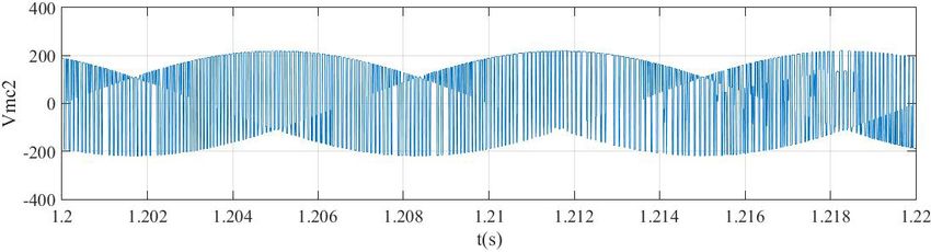
|189
Beladel et al.
Period. Polytech. Elec. Eng. Comp. Sci., 65(3), pp. 186–195, 2021
Fig. 4 Basic topology of the input stage
Fig. 6 Space vector locations for maximum DC voltage
Table 1 Duty cycle and switching pattern of the rectifier
π π π π π 5π
2.2.1 Common-Mode Voltage (CMV)
θ − ~
6 6
~
6 2 2
~
6 It is well know that the Common-Mode Voltage cause cur-
Duty Cycle d1 d2 d1 d2 d1 d2 rents flow through the stray capacitances in the motor when
Values dba dca dbc dac dcb dab supplying induction machines by the usual inverter topolo-
Conducting Sab Scn Sbp gies. As this current find their way through the conductive
Switches Sbn Scn Sbp Sab Scn San parts or components of the motor to the grounded stator case,
especially the bearings and shaft, this forms the so-called
bearing currents [15–19]. In a dual inverter system feeding
an open-end load, the CMV can be calculated as follows:
1
vcm = ( v A1G + vB1G + vC1G + v A2G + vB 2G + vC 2G ) , (2)
6
where v A1G , vB1G , vC1G , v A2G , vB 2G , vC 2G are the output ter-
minal voltages of the both virtual inverters with respect to the
power supply grounded to neutral point as shown in Fig. 2.
For the reference neutral point "0" in Fig. 2, the equa-
tion for the CMV can be rewritten as follows:
Fig. 5 The maximum DC-link voltage at the output side of the
vcm = vCm 0 + v0G , (3)
rectifier stage
where
Considering V11 – V81 as the voltage vectors for inverter 1, 1
vcm 0 = ( v A10 + vB10 + vC10 + v A20 + vB 20 + vC 20 )
then the state of the switches for inverters is given in 6
Table 2. vcm0 is the Common-Mode Voltage referred to the refer-
As it was mentioned that virtual inverter of the IMC ence neutral point "0" v0G is the voltage between the ref-
can produce eight space voltage vectors as shown in Fig. 6. erence neutral point "0" and the power supply grounded
neutral point and it can be calculated as follow:
Table 2 Voltage vectors for inverter
1 1
V [1 0 0] v0G = sapnVra + sbpnVrb + scpnVrc , (4)
2
1
1
V2 [1 1 0]
where:
V31 [0 1 0]
V41 [0 1 1] sapn =
1
2
(
sap + san , )
V51 [0 0 1]
V61 [1 0 1] sbpn
1
(
= sbp + sbn ,
2
)
1
V [1 1 1]
( )
7
1
V81 [0 0 0] scpn = scp + scn .
2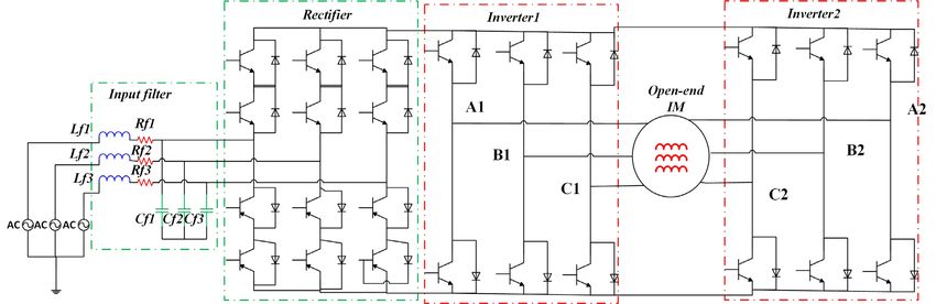
190|Beladel et al.
    Period. Polytech. Elec. Eng. Comp. Sci., 65(3), pp. 186–195, 2021

Where sip, sin are the upper and lower switching state of                     The principle idea of the DTC is to select the best volt-
the rectifier stage, respectively with i = a, b, c and Vrk with            age vector which keeps the flux and the torque within
k = a, b, c is the input phase voltage.                                    a defined permitted bandwidth with least inflation [23, 24].
                                                                           The block diagram of the DTC scheme is shown in Fig. 7.
3 Direct Torque Control of open-end winding induction                         The stator flux vector can be calculated using the mea-
motor                                                                      sured current and voltage.
Several approaches have been proposed and applied for                      dψ s
the selection of the adequate voltage space vectors used                        = U s − Rs I s                                         (5)
                                                                            dt
for the Direct Torque Control [20–22]. Fig. 6 shows the
possible space vectors of the inverter output phase volt-                  ψ ds = ∫ (U ds − Rs I ds ) dt                               (6)
ages, which divide the space to six sectors. All the sec-
tors possess the same angle of π/3 radian and are distrib-
                                                                           ψ qs = ∫ (U qs − Rs I qs ) dt                               (7)
uted equally along the plan space where each sector is                       The electromagnetic torque developed by the IM is
delimited by two voltage space vector. If the stator flux                  expressed as follows:
space vector is located in the kth sector, that k = 1,2,…6,
its magnitude can be increased using the voltage vectors                   Tem =
                                                                                   3
                                                                                   2
                                                                                        (                   )
                                                                                     p ψ ds I qs −ψ qs I ds ,                           (8)
k, k + 1, k – 1 and can be decreased using the voltage vec-
tors k + 2, k – 2, k + 3, [13]. However, the selected voltage              where LS is the stator self-inductance; Lr is the rotor self-in-
vector will also affect the output torque of the Induction                 ductance in the stator reference frame; p is the number of
Motor. From Table 2, the states of the inverter switches                   pole pairs. ψds and ψqs are the stator fluxes following the
are defined by a set of three binary signals based on the                  d and q axis, respectively and θ is the angle between the
six possible active space vectors, the transition from one                 two fluxes. The estimated flux and torque are then com-
state to another requires only a change of one switch state                pared with their reference values; the result values from
among switches at the three-inverter legs. Whereas, only                   these comparisons are introduced into the corresponding
one vector among the three vectors will be applied depend-                 hysteresis comparators respectively. Furthermore, outputs
ing on the torque and the flux errors [16].                                of the comparators with the position of the stator flux are
    As it was mentioned that virtual inverter of the IMC                   used as inputs for the switching table. Finally, based on
can produce eight space voltage vectors as shown in Fig. 6                 the data from the switching table, the control signals of the
and are given in Table 3. This means that 64 combinations                  switches for both virtual inverters are obtained. The main
of space vectors can be obtained between the two virtual                   aim is to ensure that the flux and the torque remain within
inverters which is similar to total number of the three-                   their desired tolerance band and rejoin promptly to their
level Neutral Point Clamped (NPC) inverter [10]. Hence                     reference trajectories [24, 25].
the voltage applied to the OEWIM is seen as a three-level
voltage power supply.

Table 3 Phase to neutral voltages of three-phase voltage source inverter
Switching    Switches      Phase       Phase       Phase       Space
state          on         voltage     voltage     voltage      vector
1              1,4,6      (2/3)VDC   –(1/3)VDC   –(1/3)VDC   v1ph (100)
2              1,3,6      (1/3)VDC    (1/3)VDC   –(2/3)VDC    v2ph (110)
3              2,3,6     –(1/3)VDC    (2/3)VDC    (2/3)VDC   v3ph (010)
4              2,3,5     –(2/3)VDC    (1/3)VDC    (1/3)VDC    v4ph (011)
5              2,4,5     –(1/3)VDC   –(1/3)VDC    (2/3)VDC   v5ph (001)
6              1,4,5      (1/3)VDC   –(2/3)VDC    (1/3)VDC    v6ph (101)
7              1,3,5         0           0           0       v7ph (000)
8              2,4,5         0           0           0        v8ph (111)
                                                                                            Fig. 7 DTC scheme with speed regulation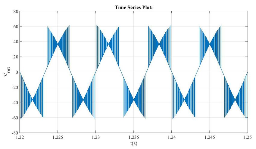
|191
Beladel et al.
Period. Polytech. Elec. Eng. Comp. Sci., 65(3), pp. 186–195, 2021
4 Simulation results and discussions Simulation results for the output voltages of both IMCs,
The simulation model of the overall system which pres- Vmc1 and Vmc2 for phase "A" are presented in Fig. 8 and the
ents the open-end winding induction machine fed by input currents are presented in Fig. 9. Figs. 10 and 11 show
a Dual-output Indirect Matrix Converter has been built in the Common-Mode Voltages VCm0 referred to the reference
Matlab/Simulink environment. The model is mainly based neutral point and the voltage v0G which present the differ-
on three main parts namely, the d–q Induction Motor, the ence of potential between the reference neutral point and
Dual Indirect Matrix Converter and the Direct Torque the power supply grounded neutral point as defined in
Control block. The output voltage is characterized by the Eqs. (3) and (4). The stator flux trajectory in the d–q frame
magnitude and the frequency of 350V and 50 Hz, respec- is presented in Fig. 12, it is clear that the both components
tively. The parameters of the induction machine and the of the flux following d and q axis are shifted by π/2 at each
input voltage are given in Table 4. On the other hand, due time step due to the circular form of the flux. Furthermore,
to the distortion which can occur in the input current and it is obvious that this trajectory has less ripples which is
to prevent the propagation of this type of harmonic pollu- explained by the tight band of this trajectory, this proves
tion towards the source, an input LC filter is inserted in the clearly the high performance of the application of the DTC
input side as shown in Fig. 2. control technique to the dual IMC feeding an Open-End
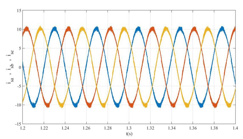
Winding IM. Fig. 13 shows stator flux in d-axis and stator
Table 4 Simulation parameters
flux in q-axis separately which proved the aforementioned
Vs Input voltage 350 V
explanation depicted from the flux trajectory. Fig. 14 shows
fs Input frequency 50 Hz
the waveforms of the power supply phase voltage, the input
fo Output frequency 50 Hz
phase current of IMC and the motor current. It is obvious
Lf Filter inductance 0.03H
that the input current of the IMC is nearly sinusoidal, but
Rf Filter Resistance 0.5 Ω
it contains some harmonics components due to the switch-
Cf Filter Capacitance 25e-6 F
ing operation dynamics and to the switching frequency.
Rs Stator resistance 4.85 Ω
This current is in phase with the power supply voltage
Rr Rotor resistance 3.81 Ω
which means that the input power factor is greatly improved
Ls Stator inductance 0.274
and its value is near to unity. On the other side, the current
Lr Rotor inductance 0.274 H
absorbed by the IM which is the same current supplied at
Lm Mutual inductance 0.258 H
the output side of the IMCs has a frequency of 23 Hz with
(a)
(b)
Fig. 8 Output phase voltages (a) first matrix converter, (b) second matrix converter)
192|Beladel et al.
    Period. Polytech. Elec. Eng. Comp. Sci., 65(3), pp. 186–195, 2021

                                                                        sinusoidal waveform which means that the harmonics con-
                                                                        tent is nearly null. This is due to the low-pass filter behav-
                                                                        ior of the IM windings and therefore, there is no need for
                                                                        inserting extra filters at the output side of the IMCs.
                                                                           Fig. 15 shows the behavior of the speed Induction Motor
                                                                        at starting up and speed reversal modes. At start-up the
                                                                        machine speed reaches to the reference speed (150 rad/s)
                                                                        within a very short time, then the motor is loaded at the
                                                                        instant of 0.5 s where a zoom is presented to demonstrate
                 Fig. 9 Three-phases stator currents                    the performance of the speed motor in more detail. After
                                                                        loading the machine, the speed drops and due to the closed
                                                                        loop control it rejoins the reference speed within a negli-
                                                                        gible time. At t = 1.5 s, the load is removed where it can
                                                                        be seen clearly in the zoom window that the motor speed

                Fig. 10 Common-Mode Voltage, VOG

                                                                                      Fig. 13 Stator d-axis flux and q-axis flux

               Fig 11 Common-Mode Voltage, VCMO

                                                                         Fig. 14 Waveforms of the Induction Motor in steady-state operation
                                                                               showing asynchronous operation of the matrix converter

 Fig. 12 Flux circular trajectory of DTC based on IMC with optimum
                                switching                                                    Fig. 15 Speed of the motor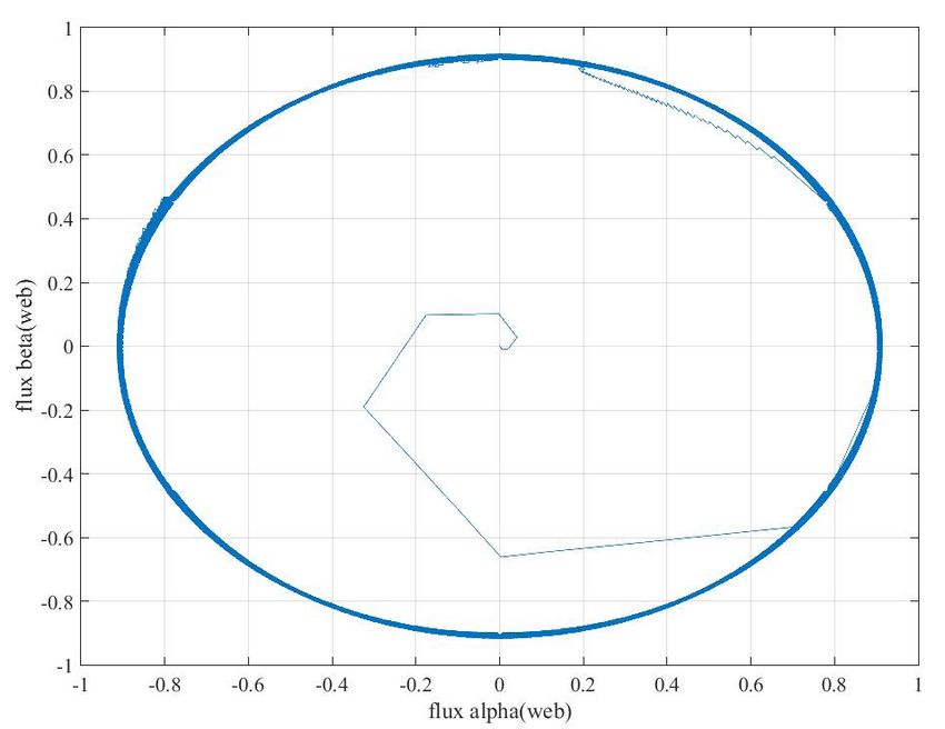
|193
                                                                                                                               Beladel et al.
                                                                          Period. Polytech. Elec. Eng. Comp. Sci., 65(3), pp. 186–195, 2021

increases within a very short time and settles down at the                application to overcome some disadvantages associated
reference speed which proved the high dynamic of the                      with rectifier-inverter based Induction Motor drives in the
used controller. It can be note also that the torque devel-               conventional topologies.
oped by the IM increases during the application of the
load to overcome the resistive torque imposed by the load                 5 Conclusions
application as shown in Fig. 16. At t = 2 s the reference                 In the present paper the application of the Direct Torque
speed is reversed to -150 rad/s where one again the motor                 Control on the DIMC feeding an open-end induction drive
rejoins its reference speed very quickly as it can be seen in             has been investigated. The simulation results show clearly
Fig. 15. The developed torque responses dynamically and                   the main advantages of the open-end winding induction
accurately to these changes following the increase or the                 machines in comparison with their counterpart, where
decrease of the applied load as shown in Fig. 16. This high               their dynamic behavior performance are well improved,
dynamic response to the speed change and even the load                    such as a fast response to the reference speed changes,
change proves the high performance quality of the pro-                    fast torque response to the variations of load, a reduced
posed control and the topology of the Open-End Winding                    Common-Mode Voltage and a nearly sinusoidal current
IM presented in this paper in comparison with conven-                     waveform at the source side with a neglected phase shift
tional topology and other control techniques. Indeed,                     referred to the power source voltage. On the other side,
the OEWIM in conjunction with the proposed dual IMC                       the use of the dual topology converter offers more flexi-
can be a promising solution for a very large industrial                   bility in terms of the control and the switching frequency.

                                                                    (a)

                                                                     (b)
            Fig. 16 (a) Change in Speed and Torque on-load condition, and (b) Zoom Change in Speed and Torque on-load condition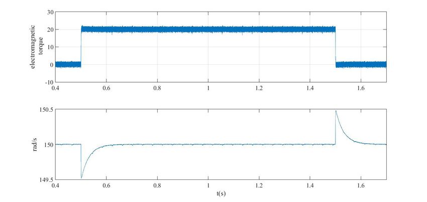
194|Beladel et al.
    Period. Polytech. Elec. Eng. Comp. Sci., 65(3), pp. 186–195, 2021

Furthermore, this topology can benefit from the uncou-                        immediate maintenance is delicate or even difficult and
pled control of the winding in the three-phase IM which                       the CMV is presenting a serious problem due to birth of
mean that it can support the faults in a better way in com-                   a current circulation in the IM stator case, mainly in the
parison with the classical topologies. The obtained results                   bearings. As a perspective, the multi-level matrix con-
in this paper prove clearly the advantages of the presented                   verter can be used to give more flexibility to the con-
system for improving the dynamic behaviors of the IM                          trol of such topology for improve the quality of absorbed
and the better flexibility of the DIMC control. It can be                     power from the power source and delivered power to the
concluded that the presented topology is a promising                          load and finally to ensure a fault tolerant system in heavy
application in the industrial process where the problem of                    industrial applications.

References
[1]   Erdman, J. M., Kerkman, R. J., Schlegel, D. W., Skibinski, G. L.        [10] Satheesh, G., Reddy, T. B., Babu, C. S. "DTC of Open End Winding
      "Effect of PWM inverters on AC motor bearing currents and shaft              Induction Motor fed by two space-vector-modulated inverters",
      voltages", IEEE Transactions on Industry Applications, 32(2),                In: 2011 Annual IEEE India Conference, Hyderabad, India, 2011,
      pp. 250–259, 1996.                                                           pp. 1–6.
      https://doi.org/10.1109/28.491472                                            https://doi.org/10.1109/INDCON.2011.6139579
[2]   Muetze, A., Sullivan, C. R. "Simplified Design of Common-Mode           [11] Matteini, M. "Control Techniques for Matrix Converter Adjustable
      Chokes for Reduction of Motor Ground Currents in Inverter Drives",           Speed Drives, PhD Thesis, University of Bologna, 2001. [online]
      IEEE Transactions on Industry Applications, 47(6), pp. 2570–2577,            Available at: http://www.die.ing.unibo.it/dottorato_it/Matteini/
      2011.                                                                        Matteini_PhD_part1.pdf [Accessed: 25 November 2020]
      https://doi.org/10.1109/TIA.2011.2170101                                [12] Riedemann, J., Peña, R., Cárdenas, R., Clare, J., Wheeler, P., Blasco-
[3]   Riedemann, J., Clare, J. C., Wheeler, P. W., Blasco-Gimenez, R.,             Gimenez, R. "Control strategy of a dual-inverter system for an open-
      Rivera, M., Peña, R. "Open-End Winding Induction Machine Fed                 end winding induction machine based on indirect matrix converter",
      by a Dual-Output Indirect Matrix Converter", IEEE Transactions on            In: 2014 16th European Conference on Power Electronics and
      Industrial Electronics, 63(7), pp. 4118–4128, 2016.                          Applications, Lappeenranta, Finnland, 2014, pp. 1–8.
      https://doi.org/10.1109/TIE.2016.2531020                                     https://doi.org/10.1109/EPE.2014.6910997
[4]   Kolar, J. W., Friedli, T., Rodriguez, J., Wheeler, P. W. "Review        [13] Kumar, D., Wheeler, P., Clare, J., Kim, T.-W. "Multi-motor drive
      of Three-Phase PWM AC–AC Converter Topologies", IEEE                         system based on a two-stage direct power conversion topology
      Transactions on Industrial Electronics, 58(11), pp. 4988–5006, 2011.         for aerospace applications", In: 4th IET Conference on Power
      https://doi.org/10.1109/TIE.2011.2159353                                     Electronics, Machines and Drives (PEMD 2008), York, UK, 2008,
[5]   Riedemann, J., Peña, R., Blasco-Gimenez, R. "A resonant current              pp. 607–610.
      control of an open-end winding induction motor fed by an indi-               https://doi.org/10.1049/cp:20080593
      rect matrix converter", In: 2015 IEEE Applied Power Electronics         [14] Abu-Rub, H., Iqbal, A., Guzinski, J. "High Performance Control of
      Conference and Exposition (APEC), Charlotte, NC, USA, 2015,                  AC Drives with MATLAB/Simulink Models", John Wiley & Sons,
      pp. 2346–2350.                                                               Inc., Chichester, UK, 2012.
      https://doi.org/10.1109/APEC.2015.7104676                                    https://doi.org/10.1002/9781119969242
[6]   Ahmed, S. M., Abu-Rub, H., Salam, Z. "Common-Mode Voltage               [15] Li, Y., Liu, W. "A Novel Direct Torque Control Method for
      Elimination in a Three-to-Five-Phase Dual Matrix Converter Feeding           Induction Motor Drive System Fed by Two-stage Matrix Converter
      a Five-Phase Open-End Drive Using Space-Vector Modulation                    with Strong Robustness for Input Voltage", In: 2007 2nd IEEE
      Technique", IEEE Transactions on Industrial Electronics, 62(10),             Conference on Industrial Electronics and Applications, Harbin,
      pp. 6051–6063, 2015.                                                         China, 2007, pp. 698–702.
      https://doi.org/10.1109/TIE.2015.2420038                                     https://doi.org/10.1109/ICIEA.2007.4318496
[7]   von Jauanne, A., Zhang, H. "A dual-bridge inverter approach to elim-    [16] Faraji, V., Aghasi, M., Khaburi, D. A., Kalantar, M. "Direct torque
      inating common-mode voltages and bearing and leakage currents",              control with improved switching for induction motor drive sys-
      IEEE Transactions on Power Electronics, 14(1), pp. 43–48, 1999.              tem fed by indirect matrix converter", In: National Conference on
      https://doi.org/10.1109/63.737591                                            Electrical, Electronics and Computer Engineering, Bursa, Turkey,
[8]   Surya Prakash, M. N., Srinivas, S. "Field oriented control of an open        2010, pp. 309–314. [online] Available at: https://ieeexplore.ieee.org/
      end winding induction machine with zero common mode voltage",                document/5698221 [Accessed: 25 November 2020]
      In: 2017 National Power Electronics Conference (NPEC), Pune,            [17] Huber, L., Borojevic, D. "Space vector modulated three-phase to
      India, 2017, pp. 352–357.                                                    three-phase matrix converter with input power factor correction",
      https://doi.org/10.1109/NPEC.2017.8310484                                    IEEE Transactions on Industry Applications, 31(6), pp. 1234–1246,
[9]   Takahashi, I., Noguchi, T. "A New Quick-Response and High                    1995.
      Efficiency Control Strategy of an Induction Motor", IEEE                     https://doi.org/10.1109/28.475693
      Transactions on Industry Applications, IA-22(5), pp. 820–827, 1986.
      https://doi.org/10.1109/TIA.1986.4504799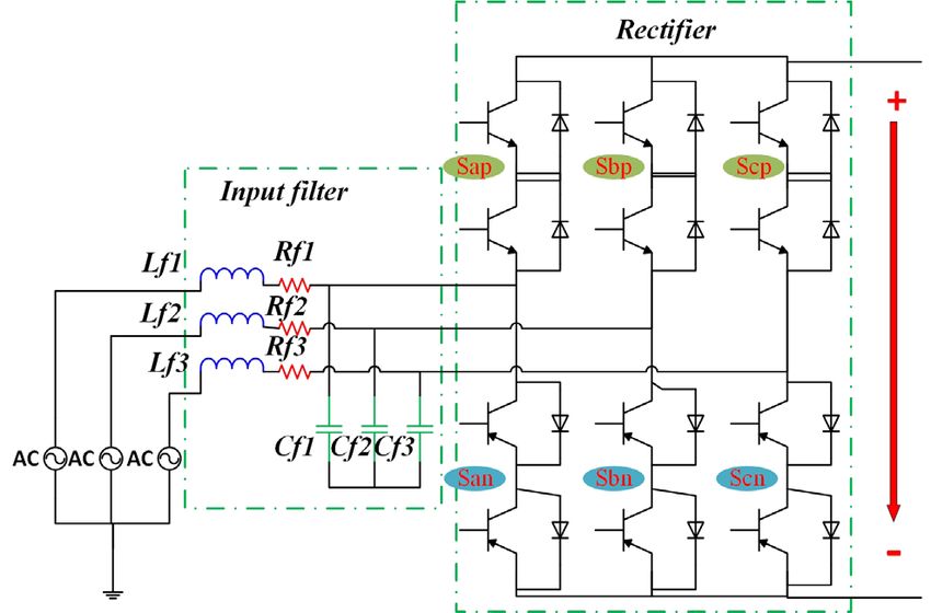
|195
                                                                                                                                    Beladel et al.
                                                                               Period. Polytech. Elec. Eng. Comp. Sci., 65(3), pp. 186–195, 2021

[18] Sunter, S., Clare, J. C. "A true four quadrant matrix converter induc-   [22] Lee, K.-B., Blaabjerg, F. "An Improved DTC-SVM Method for
     tion motor drive with servo performance", In: PESC Record. 27th               Sensorless Matrix Converter Drives Using an Overmodulation
     Annual IEEE Power Electronics Specialists Conference, Baveno,                 Strategy and a Simple Nonlinearity Compensation", IEEE
     Italy, 1, 1996, pp. 146–151.                                                  Transactions on Industrial Electronics, 54(6), pp. 3155–3166, 2007.
     https://doi.org/10.1109/PESC.1996.548573                                      https://doi.org/10.1109/TIE.2007.905914
[19] Beladel, A., Kouzou, A., Hafaifa, A., Mahi, D., Sünter, S. "Three-       [23] Buja, G. S., Kazmierkowski, M. P. "Direct torque control of PWM
     Phase Open-End Load supplied by a Dual AC-AC Converter                        inverter-fed AC motors - a survey", IEEE Transactions on Industrial
     based on Optimum-Amplitude Venturini Method", Electrotehnica,                 Electronics, 51(4), pp. 744–757, 2004.
     Electronica, Automatica (EEA),66(3), pp. 35–42, 2018. [onine]                 https://doi.org/10.1109/TIE.2004.831717
     Available     at:     http://www.eea-journal.ro/ro/d/5/p/EEA66_3_5       [24] Benachour, A., Berkouk, E. M., Mahmoudi, M. O. "A New Direct
     [Accessed: 25 November 2020]                                                  Torque Control of Induction Machine Fed by Indirect Matrix
[20] Hava, A. M., Ün, E. "Performance Analysis of Reduced Common-                  Converter", Revue Roumaine des Sciences Techniques – Série
     Mode Voltage PWM Methods and Comparison With Standard                         Électrotechnique et Énergétique, 62(1), pp. 25–30, 2017. [online]
     PWM Methods for Three-Phase Voltage-Source Inverters", IEEE                   Available at: http://revue.elth.pub.ro/upload/82006305_ABenachour_
     Transactions on Power Electronics, 24(1), pp. 241–252, 2009.                  RRST_1_2017_pp_25-30.pdf [Accessed: 25 November 2020]
     https://doi.org/10.1109/TPEL.2008.2005719                                [25] Akagi, H., Shimizu, T. "Attenuation of Conducted EMI Emissions
[21] Sünter, S., Altun, H., Clare, J. C. "A Control Technique for                  From an Inverter-Driven Motor", IEEE Transactions on Power
     Compensating the Effects of Input Voltage Variations on Matrix                Electronics, 23(1), pp. 282–290, 2008.
     Converter Modulation Algorithms", Electric Power Components                   https://doi.org/10.1109/TPEL.2007.911878
      and Systems, 30(8), pp. 807–822, 2002.
      https://doi.org/10.1080/15325000290085037
You can also read