Towards Building eco-friendly and emission less Electric Scooter
←
→
Page content transcription
If your browser does not render page correctly, please read the page content below

Journal of Physics: Conference Series

PAPER • OPEN ACCESS

Towards Building eco-friendly and emission less Electric Scooter
To cite this article: T Lokitha et al 2021 J. Phys.: Conf. Ser. 1997 012043

View the article online for updates and enhancements.

                                This content was downloaded from IP address 46.4.80.155 on 17/09/2021 at 03:20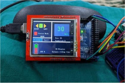
Asian Conference on Intelligent Computing and Data Sciences (ACIDS) 2021                 IOP Publishing
Journal of Physics: Conference Series           1997 (2021) 012043 doi:10.1088/1742-6596/1997/1/012043

Towards Building eco-friendly and emission less Electric
Scooter

                     T Lokitha1, B Venkatesh1, S Arun Kumar1 and S Sasikala1
                     1
                      Department of ECE, Kumaraguru College of Technology, Coimbatore- 641049,
                     Tamilnadu, India.

                     lokitha.18ec@kct.ac.in, venkatesh1.18ec@kct.ac.in.

                     Abstract. Electric vehicles are becoming more important, as not only to reduce carbon emission
                     but also to reduce the dependency on normal combustion engine vehicles. Most of the
                     universities have really big campuses. To make the mobility in campus easier, the harmless and
                     power-controlled vehicle with safety technologies is introduced. Besides, it also reduces time
                     consumption. Further, it aids differently abled persons and aged professors. This paper presents
                     the design and development of a compact, portable and weightless electric skating scooter. The
                     vehicle body design is inspired from the sea cartilaginous fish ‘String Ray’. It also includes
                     mechanical features like front shock absorber, handlebar break control, portable and handle bar
                     height adjustment. The electrical and electronic features such as obstacle detector, fingerprint
                     and RFID (Radio-frequency identification) access, battery management system (BMS) etc., help
                     towards building a smart vehicle. Besides, it also provides a vehicle management system for
                     tracking the user details, location and condition of the vehicle through a server. The proposed
                     system with addition of mechanical, electrical and electronic features will help towards
                     enhancing the performance of an electric scooter for easy mobility. The results obtained from
                     the on-road test, CADD software and the implementation of vehicle management system has
                     been discussed.

1. Introduction
In the tech era, where time rises for the revolution in the field of motor vehicle, e-vehicles plays an
important role in the development phase. In India, a developing nation, where several decisions and
steps are being taken to reduce the usability of petrol- and diesel-powered cars by 2030 [1], the
development of e-vehicles will make a rise in usability and a sustainable environment. They have fewer
moving parts than conventional cars. This is greatly helpful in reducing pollution and has zero exhaust
emissions. In future, the price of electric-vehicle will fall [2]. Decreased usage of petroleum and gasoline
and motor oil means fewer spills and pollution in oceans, rivers and groundwater. Universities and
industry campuses generally have serious mobility problems [4]. So, the mobility for disabled students
and aged professors is even more a tough job. The main aim of our project is intra college mobility. To
make the mobility inside campus easier, the harmless and power-controlled vehicle with safety
technologies can be used which reduces time consumption and helps disabled people. Considering the
problem, the work focuses on an electric skating scooter which is really compact, portable and

              Content from this work may be used under the terms of the Creative Commons Attribution 3.0 licence. Any further distribution
              of this work must maintain attribution to the author(s) and the title of the work, journal citation and DOI.
Published under licence by IOP Publishing Ltd                          1
Asian Conference on Intelligent Computing and Data Sciences (ACIDS) 2021 IOP Publishing
Journal of Physics: Conference Series 1997 (2021) 012043 doi:10.1088/1742-6596/1997/1/012043
weightless. This electric scooter has safety electronic technologies. The maximum speed of the scooter
is 25 kilometres per hour. Our electric skating scooter has a modern design which is compact and easy
to carry. The scooter handlebar height can be adjusted according to the rider's need. The scooter has a
front shock absorber which smoothens the ride. Electronic safety technologies like obstacle detector,
fingerprint access, BMS (Battery Management System) to monitor voltage, temperature, SOC and SOH
are really useful for the rider ensuring comfort and safety while riding the scooter. This technology
lowers the possibility of the occurrence of accidents on campus. The main objective is to design and
develop an electric scooter for short distance locomotion. Specifically, it aims to:
Develop a light weight and easy portable scooter.
Develop a lost cost E-vehicle.
Propose a novelty in the basic design of the scooter unlike, normal electric scooters in the
market.
Develop the outer body resistance to environmental calamities.
Develop an eco-friendly and low-cost fuel vehicle.
2. Literature review
In recent years, many research works and projects have been done in the field of electric vehicles
especially in the field of Li-ion batteries [5] and motors [9]. In [12] a study was made to look into the
power flow calculation and the design of electric vehicle model is done using MATLAB to get the best
power flow response to the energy system of the vehicle. A mathematical modelling and analysis on the
powertrain were done in [12] for the use of split-power system. This helps to verify the operational
capabilities of the motor under varying optimal conditions. Based on wireless transfer protocol, a hybrid
energy system was designed and implemented in [8] using super capacitors for high performance of the
scooter. Challenges faced by electric two wheelers in mountain roads was proposed in [16]. An electric
scooter simulation program was developed in [10] to enable more improvement in the driving skills of
the users. A portable electric scooter was designed in [17] to make the access of the vehicle much easier
and more comfortable. An integrated power module for electric scooter was designed in [13] to improve
the efficiency of power board. Taking into the account conservation of energy a solarized electric scooter
was developed in [14]. A different approach was taken in [15] to improve the appearance and ergonomic
performance using anthropometric measurement. Motor control using PID and Fuzzy PID controller is
overviewed in [6]. Vehicle performance calculations done in [18] gives a clear insight on the parameters
that has to monitored during the on-road test of the electric vehicle. The graphs shown in [18] indicates
the battery performance, consumption and efficiency during the real-world scenarios. A comprehensive
evaluation on battery technologies in the electric vehicle market is done in [19]. This helps to analyse
and compare the different types of batteries available in the market. Incentive’s knowledge is essential
for consumer awareness on electric vehicles. This is explained in [20]. Several papers and literatures
related to electric vehicles has been discussed.
3. Materials and Methods
In a qualitative experimental study, the practical difficulties in implementing an electric vehicle are
analysed. From the study, knowledge is gained on the real parameters to be taken care of while
implementing an electric vehicle. After the completion of successful design analysis in Solid works, the
mechanical design is developed using aluminium sheet. Motor controller, Li-ion battery is connected
and the vehicle is started by connecting the wires manually. To monitor the vehicle and battery certain
modules like vehicle management and monitoring system are developed. Figure.1 explains the working
flow the electric scooter. The algorithm of the work flow is given below.
STEP 1: Start
STEP 2: Initialize the display.
STEP 3: RFID reads the tag.
STEP 4: If the tag is valid state of the bike changes from OFF to ON.
2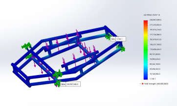
Asian Conference on Intelligent Computing and Data Sciences (ACIDS) 2021                 IOP Publishing
Journal of Physics: Conference Series           1997 (2021) 012043 doi:10.1088/1742-6596/1997/1/012043

STEP 5: User details are sent to the cloud and displayed on the server.
STEP 6: Enable and Initialize the GPS module.
STEP 7: Location is displayed on the server.
STEP 8: If the scooter starts moving speed, battery percentage are displayed on the LCD.
STEP 9: If the log out button is pressed the scooter state changes from ON to OFF.
STEP 10: User log out details are updated on the server.

                   Figure 1. Flow Diagram of the Proposed System.

                                                   3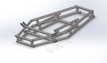
Asian Conference on Intelligent Computing and Data Sciences (ACIDS) 2021                 IOP Publishing
Journal of Physics: Conference Series           1997 (2021) 012043 doi:10.1088/1742-6596/1997/1/012043

         Sensors and
          modules

                                                                   Motor Controller                Motor
          Arduino Mega                    Battery

      Server           User Interface

                    Figure 2. Block Diagram of the Electronic module of the system.

From Figure 2 it is very clear that, the battery is the primary energy source or fuel for the vehicle. It
sends switch-mode signal to the controller to drive the motor. A DC- DC converter is used to step down
the voltage of the battery to 6 or 12v for the purpose of need. Hub motor is used here because of the
advantage that they are independent drive system and they require little maintenance. Arduino MEGA
is the main ECU to monitor the parameters like speed, battery percentage, location of the vehicle and
also control the ON and OFF of the vehicle with the help of RFID. All these parameters are measured
with the help of IR sensors, BMS, GPS module and RFID tag. 48v Li-ion battery is used as the fuel
source of the vehicle. Battery is connected to the motor with the help of 48v motor controller. List of
components used to design and develop the electric scooter is listed in table 1. The main systems
involved in developing the electric scooter are battery, battery management system, motor, motor
controller, vehicle monitoring system and vehicle management system. The working and functions of
all these subsystems are discussed below.

                                 Table 1. List of Hardware Components
     Name of the components                          Purpose
     Li-ion Battery                                  Energy source for the vehicle.
     Hub Motor                                       To drive the vehicle.
     Motor Controller                                To drive the motor.
     Arduino MEGA                                    Microcontroller unit.
     IR Sensor                                       To measure speed.
     GPS Module                                      To obtain the location details of the vehicle.
     RFID                                            To give access for the vehicle.
     Thin film Transistor LCD                        Dashboard of the vehicle.

3.1. Battery
The battery acts as the main fuel source for the vehicle. At recent days, lead – acid batteries are getting
replaced by Li-ion batteries because of their less running cost and less maintenance. The battery pack
used in this is electric vehicle is Li-ion. The supply from the battery is controlled using a motor controller
and this is given as input to the motor. The battery will be connected to the motor driver to deliver power
directly to the motor.

                                                       4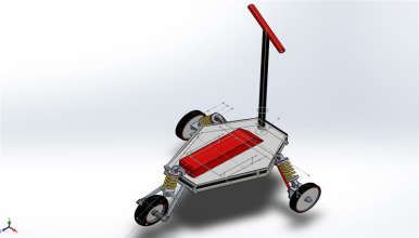
Asian Conference on Intelligent Computing and Data Sciences (ACIDS) 2021                 IOP Publishing
Journal of Physics: Conference Series           1997 (2021) 012043 doi:10.1088/1742-6596/1997/1/012043

3.2. Battery Management System
A battery management system (BMS) is a basic electronic system used to monitor the rechargeable
battery pack or cell. It monitors current, voltage, State of Charge (SOC), State of Health (SOH), depth
of discharge, state of power and coulomb flow. The battery management system is made up of many
hardware and software functional blocks which has,
     o Cut off MOSFET
     o Real Time Clock
     o Temperature monitoring system
     o Fuel gauge monitor
     o Cell voltage monitor or cell balancing circuits
All these functions blocks play a major role in monitoring each cells of the Li-ion battery pack. The
battery management system should contain accurate algorithms to measure and calculate the functional
status of the battery. A review on smart battery management system for Li-ion battery is described in
[Ali, Zafar, et al., (2019)].

3.3. Motor
Gearless hub motor is used to drive the vehicle. It is placed in the center part of the wheel. Hub motor
is actually a BLDC motor. Hall effect sensor is used to identify the position of the rotor very precisely
with the help of variation in magnetic fields. The position of the rotor is identified with the help of hall
sensor. The position of rotor is fed to the microprocessor unit with help of Rotor position circuitry. The
microprocessor gets input from the hall sensor and based on the input fed PWM signal is sent to the
switching circuit to energize the respective coils. When the permanent magnet passes through any one
of the sensors, the sensor produces a positive or negative (high/low) signal which is used to determine
the rotor position (N/S pole). Based on the output from the hall effect sensor, pulse width modulated
signal is generated. Pulse width modulation is a technique used to control the speed of many devices.
The working of PWM in motor control is discussed in [Prakosa et al., (2019)] In 555 timer IC, the
actual output is a PWM signal. The duty cycle depends on the value of the resistors. Duty
cycle=R1/(R1+R2). In microcontrollers and microprocessors there are dedicated output pin for the
PWM signal. All these processes are involved in the working of motor and calculating the speed of the
motor. To improve the torque and ripples a four-quadrant operation method of brushless motor is
employed in [Gopinath et.al., (2018)].

3.4. Motor Controller
Motor controller is the brain of EV which basically controls the motor. The parameters monitored by
the motor-controller are Motor speed , expected battery range, acceleration, direction, torque, overload
protection, start and stop of the vehicle and regenerative braking. Motor controller controls the current
and voltage of the battery to be supplied to the motor. Based on this, desired output power and the speed
and torque are controlled. A microprocessor inside the motor-controller will take care all of these
calculations. So, the processing speed of the processor should be very high.

3.5. Vehicle Monitoring System
ATmega328PArduino Mega serves as a microcontroller unit among the battery, sensors and vehicle
tracking system. In the vehicle, an IR sensor is placed near the back wheel. Whenever the sensor detects
white colour on the wheel, the count is made as 1. By this method, the rpm of the wheel is calculated
using RPM: diameter of the wheel*rpm*0.001885. With the help of rpm speed can be calculated which
is displayed on the display mounted on the handle bar. Here the RFID tag and reader acts as transmitter
and receiver. Global Positioning System is a satellite-based system used for tracking the location with
time and range. The controller then sends the information the cloud to display the location in the
webpage. Thin Film Transistor Liquid Crystal Display is used as a dashboard in this vehicle.
3.6. Vehicle management system

                                                      5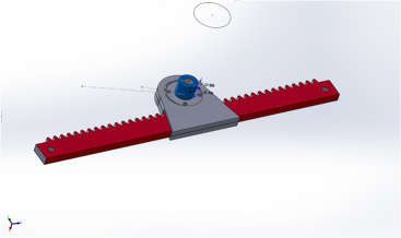
Asian Conference on Intelligent Computing and Data Sciences (ACIDS) 2021                 IOP Publishing
Journal of Physics: Conference Series           1997 (2021) 012043 doi:10.1088/1742-6596/1997/1/012043

     The main purpose of this project is to serve intra-campus locomotion. Therefore, maintaining and
monitoring all the vehicle inside the campus is not an easy task. For this purpose, a vehicle tracking
system has been developed, under which the campus management can monitor the location, user details
and temperature of the electric vehicle.

4. Results and Discussion
In order to achieve better performance and reduce real-time difficulties in the making of vehicle, the
estimation of the performance is done using CADD software. The mechanical design of the proposed
system is shown in the Figure 3,4,5,6. In the electric scooter, AISI 4130 is selected as the roll cage
material due to its high strength to weight ratio of 72 to 130 kNm/kg. The proposed design provides up
to 25.5 percentage of elongation. The wheel base is 548 mm so that it provides a minimum turning radius
of 1.3 m. The scooter is designed for a load carrying capacity of 120 kg. Results obtained from the on-
road test is listed in the table 2. Based on the results obtained from the speed test, the battery used in the
electric scooter has a discharging rate of 4.3 hrs. The range that can be covered at the economy mode is
43 km. The RFID system used in the scooter unlocks the vehicle within 3 seconds when the tag is placed
near the reader. Once the user unlocks the scooter, user information is sent to the server and the vehicle
is monitored. Since, lithium-ion battery pack is used in this scooter, all safety parameters like
temperature, voltage and current discharge, SOC have monitored under all circumstances. The functions
of the scooter like throttle performance, rolling resistance (35.316 N), gradient resistance (153.3 N),
aerodynamic drag(8.47 N) and braking system have been checked thoroughly.

                                   Table 2. On road test results comparison
               Distance (km)        Battery SoC (%) Power consumption (wh/km)
                       35              Decreases 27                       132
                       42              Decreases 33                       148
                       47              Decreases 46                       154

                            (a)                                                    (b)

                             (c)                                                    (d)

    Figure 3. Design of the E-Scooter done in CADD software (a) depicts the overall design, (b) main
    frame, (c) isometric view and (d) rack and pinion of the vehicle.

                                                       6
Asian Conference on Intelligent Computing and Data Sciences (ACIDS) 2021 IOP Publishing
Journal of Physics: Conference Series 1997 (2021) 012043 doi:10.1088/1742-6596/1997/1/012043
As shown in the Figure 4(a), Fascia or dashboard which is used to display the information like speed,
battery percentage, remaining distance of ride, mode of the vehicle user details. The RFID tag is tested
with a person’s id, the information in the respective id will be displayed on the dashboard within 5 secs
of the unlock of the vehicle. The information of the vehicle which is linked to the database displays data
of the user accessing the scooter. And it is also linked to the microcontroller and google maps for sensor
data & tracking. Figure 4(b). shows the front-end of the webpage. Parameter displayed on the server:
Log in and Log out credentials.
Battery Percentage.
Temperature of the vehicle.
Location of the vehicle with pick up and park information.
(a) (b)
Figure 4. Implementation of vehicle tracking system (a) which display the user information in the
dashboard of the vehicle (b) sewhich displays the vehicle information onto the server.
During the on-road test of the vehicle, the maximum speed obtained at the economy mode is
15kmph, cruise mode is 20 kmph and sport mode is 27kmph. And the battery last for about 4.5 hours,
3.5 hours and 2 hours respectively for the economic, cruise and sport mode.
5. Conclusion
Electric vehicles play an important role to maintain a pollution free environment. The Electric Vehicles
Market is projected to reach 26,951,318 units by 2030 all over the world. A survey says that by 2030,
the government aims to make India a 100-per cent electric-vehicle nation. To achieve this many
innovative electric vehicles designing ideas are required. In this paper, design and development of
electric scooter is studied. Each and every part included in the development has been described in detail.
In order to ensure the safety of the vehicle, vehicle tracking system has been implied. Experimental
results show the stability and ease access of the vehicle. In addition, further experimental results show
the charging and discharging of the battery. The overall design helps in decreasing pollution and
increasing the speed of intra-campus locomotion. It has an advantage of much lower running costs. The
maximum speed of the scooter is 25 kmph and the gradeability is 200. Thus, the working of the system
has been tested thoroughly and it is said to function properly and successfully. In future the following
things can be improved in the electric scooter,
Design Optimization
Weight Reductions
Improving Ergonomics
Manufacturing Cost Reduction
Vehicle Tracking System
7Asian Conference on Intelligent Computing and Data Sciences (ACIDS) 2021 IOP Publishing
Journal of Physics: Conference Series 1997 (2021) 012043 doi:10.1088/1742-6596/1997/1/012043
Acknowledgement
This project “Electric Scooter” was fully funded by the research cell of Kumaraguru college of
Technology under the grant no 1118010.
References
[1] Teri C 2019 Transition to e-vehicles may take longer than 2030: TERI chief The Economic
Times Web [Accessed on December 12,2020]
[2] Leslie Shaffer 2016 Electric vehicles will soon be cheaper than regular cars because maintenance
costs are lower CNBC Web [Accessed on December 12,2020]
[3] Pellegrino G Armando E and Guglielmi P 2009 An Integral Battery Charger with Power Factor
Correction for Electric Scooter IEEE 25 3
[4] Luigi O Bordagaray M Barreda R and Ibeasa A 2014 A Methodology to Promote Sustainable
Mobility in College Campuses Trans. Res. Pro. 3 838 – 47
[5] Khateeb A Farid M Selman M J and Al-Hallaj S 2004 Design and simulation of a lithium-ion
battery with a phase change material thermal management system for an electric scooter J. Pow.
Sourc. 128 2
[6] Chen C and Cheng M 2007 Implementation of a Highly Reliable Hybrid Electric Scooter Drive
IEEE 54 2462-73
[7] Sheu K 2008 Simulation for the analysis of a hybrid electric scooter powertrain Sci. Direct 85 7
[8] Hu J et al. 2018 Hybrid Energy Storage System of an Electric Scooter Based on Wireless Power
Transfer IEEE 14 4169-78
[9] Ravi N Ekram S and Mahajan D 2006 Design and Development of an In-Wheel Brushless D.C.
Motor Drive for an Electric Scooter 2006 International Conference on Power Electronic Drives
and Energy Systems New Delhi 1-4
[10] Jannink J A Erren-Wolters M Kort C and Kooij H 2008 An Electric Scooter Simulation Program
for Training the Driving Skills of Stroke Patients with Mobility Problems: A Pilot Study 11 6
[11] Fodorean D Idoumghar L and Szabo L 2013 Motorization for an Electric Scooter by Using
Permanent-Magnet Machines Optimized Based on a Hybrid Metaheuristic Algorithm 62 39-49
[12] Kaloko B and Purnomo M 2011 Design and Development of Small Electric Vehicle using
MATLAB/Simulink Int. J. Comp. App. 24 6
[13] Chou J and WenHsiao S 2005 An anthropometric measurement for developing an electric
scooter Int. J. Indust. Erg. 35 11
[14] Iyer P Teja G R and Prasad V 2014 Design and Fabrication of Solar Electric Scooter Int. J. Res.
Engi. Sci 34
[15] Chang S Tsai J Sung B and Lin C 2013 Design of integrated power module for electric scooter
2013 World Electric Vehicle Symposium and Exhibition 1-5
[16] Nama T Gogoi A K and Tripathy P 2018 Low Power Electric Two-Wheelers for Hilly Region
IEEE 1-6
[17] Feng Y Tang Y and Wang H 2012 Portable Personal Electric Scooter Optimization Design
Research App. Mech. Mat. 203 422–26
[18] Baghdadi M 2013 Electric vehicle performance and Consumption evaluation World Elec. Veh. J.
6 30
[19] Cano Z P Banham D Ye S. et al. 2018 Batteries and fuel cells for emerging electric vehicle
markets Nat Energy 3 279–89
[20] Alan J Katalin S Anand R and Gopal 2018 Effectiveness of electric vehicle incentives in the
United States Ener. Pol. 119 349-56
8You can also read