Specification W Technical
←
→
Page content transcription
If your browser does not render page correctly, please read the page content below
Kohler PW 6000
           (160–500 kVA S2)
Parallelable up to 5 MVA/MW
                   Technical
                   Specification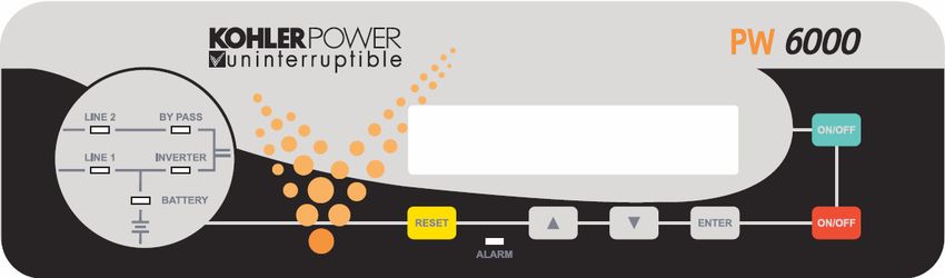
Document Control
 ISSUE               DATE                 REVISION SUMMARY

 TS_684_IE           11/01/2021           First issue (Kohler branding)

Useful Contacts
 www.kohler-ups.ie                                      Kohler Uninterruptible Power web site
 ieinfo.ups@kohler.com                                  All Hardware and Service enquiries

All product, product specifications and data are subject to change without notice to improve reliability, function, design or otherwise.
Kohler Uninterruptible Power has taken every precaution to produce an accurate, complete and easy to understand specification
document and will assume no responsibility nor liability for direct, indirect or accidental personal or material damage due to any
misinterpretation of, or accidental errors, in this manual.

© 2020 Kohler Uninterruptible Power
This manual may not be copied or reproduced without written permission of Kohler Uninterruptible Power

                                                                   TS_684_IE Kohler PW 6000 S2 (160-500kVA) Technical Specification 11/01/2021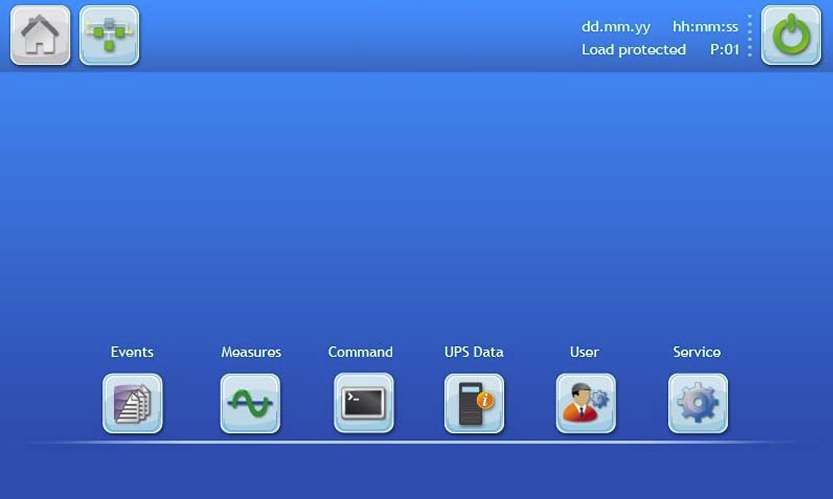
POWERWAVE 6000 S2 DESCRIPTION
Continuous power availability is essential in today’s dynamic IT and process-related environments. It is equally important
that any installed power protection system is sufficiently resilient and adaptable to handle any changes brought about by
the introduction of new server technologies, migration and centralization. Such demands are well met by the PowerWAVE
6000 S2 UPS system, which provides the foundation for continuous power availability of network-critical infrastructures
both in enterprise data centres, where business continuity has paramount importance, and in process control
environments where manufacturing continuity is essential.

The PowerWAVE 6000 S2 UPS, which is available over a model range of 160kVA to 500kVA, incorporates the latest
technological developments in power engineering and represents a completely new generation of high power, three phase
UPS systems. Its advanced double conversion VFI (Voltage and Frequency Independent) topology responds fully to both
the highest availability and environmentally friendly requirements compliant with IEC 62040-3 (VFI-SS-111) standards.

PowerWAVE 6000 S2 features innovations that combine to deliver the industry’s best key values such as: enhanced
power performance, parallel capability and connectivity’s interaction.
Kohler Uninterruptible Power specialises in the installation and maintenance of Uninterruptible Power Systems; and this
powerful UPS is just one example of our wide range of state-of-the-art power protection devices that will provide your
critical equipment with a steady and reliable power supply for many years.

PowerWAVE 6000 S2 configurations

The PowerWAVE 6000 S2 UPS can be configured to operate as a single, stand-alone UPS or several (up to 10) UPS
cabinets can be connected in parallel to operate as a multi-module UPS system. A multi-module configuration is generally
chosen either to increase a system’s total power capacity or to provide module redundancy in order to keep the load
supplied in the event of a module failure.

Due to its Decentralised Parallel Architecture (DPA) design, each PowerWAVE 6000 S2 UPS can take the leadership role
when operating in a multi-module system. This avoids a single point of failure in the parallel chain and ensures the highest
level of power availability.
System expansion
Most data centres present a low initial power demand which increases as the data centre grows to its full capacity; and it
is essential that the installed power protection system can be expanded to meet a growing demand without compromising
the existing load. This situation is easily managed in a PowerWAVE 6000 S2 multi-module installation by adding an
additional UPS cabinets to an existing system to increase the overall system capacity without having to temporarily
transfer the load to the raw mains supply. This results in the highest level of power availability, interruption free.
Key features
The highlights of this innovative UPS solution include its high reliability, upgrade ability, low operating costs and excellent
electrical performance.

 KEY FEATURES
 Compact size, small foot print                                     Space saving on expensive floor space
 Flexible battery management                                        Advanced management of battery charging and preventive failure
                                                                    diagnostics avoids premature deterioration of battery life.
 Best in class ac-ac efficiency, up to 96%                          Energy-Operational cost savings (TCO)
 Low input power factor (near unity)                                Cost savings during installation and the entire life cycle (TCO)
 Blade-server-friendly power; full power from 0.9 lead to 0.9 lag   No de-rating required with leading PF loads
 Very low input current distortion THDi                             Gen-set power and installation cost saving
 THDi = < 3.5% @ 100% load

TS_684_IE Kohler PW 6000 S2 (160-500kVA) Technical Specification 11/01/2021                                                            1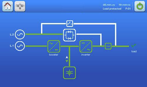
GENERAL SPECIFICATIONS
    This Technical Specification provides detailed technical information on the mechanical, electrical and environmental
    performance of the PowerWAVE 6000 S2 60-500 kVA model range, and is intended to support and provide answers to
    tender and end-user requirements.

     MECHANICAL CHARACTERISTICS 160/200 kVA

                                                     160 kVA           200 kVA

     Dimensions (WxHxD)                      mm   850 x 1820 x 750
     Dimensions with elevation kit (WxHxD)   mm   850 x 1975 x 750
     Weight                                  kg          290              310
     Colour                                       Black (RAL 9005)
     Batteries                                    Fitted in external enclosure
     Input and output power cable entry           Bottom
     Exhaust cooling air                          Rear

     MECHANICAL CHARACTERISTICS 250/300 kVA

                                                     250 kVA           300 kVA

     Dimensions (WxHxD)                      mm   1100 x 1920 x 750
     Dimensions with elevation kit (WxHxD)   mm   1100 x 1975 x 750
     Weight                                  kg          390              410
     Colour                                       Black (RAL 9005)
     Batteries                                    Fitted in external enclosure
     Input and output power cable entry           Bottom
     Exhaust cooling air                          Rear

     MECHANICAL CHARACTERISTICS 400/500 kVA

                                                     400 kVA           500 kVA

     Dimensions (WxHxD)                      mm   1650 x 1994 x 850
     Dimensions with elevation kit (WxHxD)   mm   1650 x 2094 x 850
     Weight                                  kg          950             1000
     Colour                                       Black (RAL 9005)
     Batteries                                    Fitted in external enclosure
     Input and output power cable entry           Bottom
     Exhaust cooling air                          Top

2                                                    TS_684_IE Kohler PW 6000 S2 (160-500kVA) Technical Specification 11/01/2021
MECHANICAL CHARACTERISTICS 400/500 kVA + Top Cable Entry
(TCE) cabinet
400 kVA 500 kVA
Dimensions (WxHxD) mm 2150 x 1994 x 850
Dimensions with elevation kit (WxHxD) mm 2150 x 2094 x 850
Weight witch TCE basic kg 950+115 1000+115
Weight with TCE single input feed + cables kg 950+245 1000+245
Weight with TCE dual input feed + cables kg 950+285 1000+285
Colour Black (RAL 9005)
Batteries Fitted in external enclosure
Input power cable entry Top
Output power cable entry Bottom
Exhaust cooling air None
SYSTEM CHARACTERISTICS
Topology On-line, double conversion, Voltage and Frequency Independent (VFI)
Technology Second generation transformerless design
Parallel configuration expansion For added redundancy and/or capacity a parallel system can be extended to
up to 10 modules on request
Load 25% 50% 75% 100%
Double conversion AC/AC efficiency with
fully charged battery and linear load (PF = 1) % eff. 95.5% 96.0% 95.5% 95.0%
INPUT CHARACTERISTICS
160 kVA 200 kVA 250 kVA 300 kVA 400 kVA 500 kVA
Input voltage VAC 3x 380/220V+N, 3x 400/230V+N, 3x 415/240V+N
Input voltage tolerance (ref to 3x400/230V) VAC (-23% to +15%) 3x308/177V to 3x460/264V forBATTERY CHARACTERISTICS
160 kVA 200 kVA 250 kVA 300 kVA 400 kVA 500 kVA
Variable number of 12V battery blocks (only No. 44/50 50 44/50
even numbers allowed)
Max. battery charger current A 50 60 100
Battery type Maintenance-free VRLA or NiCd
Temperature controlled charger Yes (temperature sensor optional)
Battery charging curve Ripple-free: IU (DIN 41773)
Battery test Automatic and periodic (adjustable)
OUTPUT CHARACTERISTICS
160 kVA 200 kVA 250 kVA 300 kVA 400 kVA 500 kVA
Output rated power kW 160 *200 250 300 400 500
(@min 44 battery blocks)
Output current In (PF=1.0) A 232 *290 361 433 577 722
(@min 44 battery blocks)
Output rated voltage VAC 3x 380/220 or 3x 400/230 or 3x 415/240
Output voltage stability (Static) % < ± 1.0
Output voltage stability (Dynamic) % < ±4 (with load step 0-100%, 100-0%)
Output voltage distortion with linear load % < 2 with linear load
Output voltage distortion with non-linear load % < 4 (EN 62040-3:2001)
Output frequency Hz 50 or 60
Output frequency tolerance % ±0.1 free-running, quartz oscillator
±2 or ±4 with mains synchronised (selectable)
Frequency slew rate Hz/s 1.0
Output waveform Sinewave with 0deg. phase imbalance @100% unbalanced load
Permissible unbalanced load % 100% (all 3 phases independently regulated)
Overload capability on inverter % At PF=1.0 110% load for 10 minutes
At PF=1.0 135% load for 1 minute
At PF=0.9 125% load for 10 minutes
At PF=0.9 150% load for 1 minute
Inverter short circuit capability A 1.9x 2.1x 2.0x 2.0x 2.0x 2.0x
(x rated output for 40ms)
Bypass short circuit capability 10x rated In for 10 ms
Crest factor 3:1
Bypass operation At ±15.0% of nominal input voltage
* With 50 battery blocks only
4 TS_684_IE Kohler PW 6000 S2 (160-500kVA) Technical Specification 11/01/2021OUTPUT POWER VERSUS COS ø
Inductive (lagging COS ø) Unity Capacitive (leading COS ø)
Module 0.6 0.65 0.7 0.75 0.8 0.85 0.9 0.95 1.0 0.95 0.9 0.85 0.8
160 kVA 160 160 160 160 160 160 160 160 160 160 160 156 154
KW 96 104 112 120 128 136 144 152 160 152 144 132 122
200* kVA 200 200 200 200 200 200 200 200 200 200 200 195 194
KW 120 130 140 150 160 170 180 190 200 190 180 166 154
250 kVA 250 250 250 250 250 250 250 250 250 250 250 245 241
KW 150 163 175 188 200 213 225 238 250 238 225 208 193
300 kVA 300 300 300 300 300 300 300 300 300 300 300 294 291
KW 180 195 210 225 240 255 270 285 300 285 270 249 231
400 kVA 400 400 400 400 400 400 400 400 400 400 400 392 388
KW 240 260 280 300 320 340 360 380 400 380 360 333 310
500 kVA 500 500 500 500 500 500 500 500 500 500 500 490 485
KW 300 325 350 375 400 425 450 475 500 475 450 417 338
Vout=230Vac (L-N), 50 Hz, with minimum of 44 battery blocks (*50 Battery blocks on 200kVA model)
STANDARDS
Safety EN62040-1-1:2003 EN60950-1:2001/A11/;2004
Electromagnetic compatibility IEC/EN 62040-2:2005, IEC/EN61000-3-2:2000,
IEC/EN61000-6-2:2001,
Performance EN 62040-3:2001
Product certification CE
Degree of protections IP20
TS_684_IE Kohler PW 6000 S2 (160-500kVA) Technical Specification 11/01/2021 5ENVIRONMENTAL CHARACTERISTICS
160 kVA 200 kVA 250 kVA 300 kVA 400 kVA 500 kVA
Audible noise @ 100 load (approximate dBA < 69 < 71 >78.5
values only)
Ambient temperature for UPS °C 0-40
Battery temperature (recommended) °C 20
Battery storage time at 20°C Maximum 6 months
Fan assisted cooling air flow Front entry, rear exit Front entry top exit
Airflow (25 - 30°C) with 100% non-linear load m³/h 2500 3350 6550
Heat dissipation with 100% non-linear load W 10213 12766 15957 19149 24000 30000
Heat dissipation with 100% non-linear load BTU/h 34856 43570 54462 65355 81913 102389
Heat dissipation without load W 1500 2300 4000
Relative air-humidity Maximum 95% (non-condensing)
Max altitude above sea level without derating 1000m (3300ft) without derating
De-rating factor for use at altitudes above Height above sea level (m/ft) Derating factor for power
1000m sea level according (IEC 62040-3) 1500 / 4850 0.95
2000 / 6600 0.91
2500 / 8250 0.86
3000 / 9900 0.82
COMMUNICATION OPTIONS
Power Management Display (PMD) LCD display and mimic diagram showing UPS operational status
(Optional 7” TFT touch-screen display standard on 400/500kVA model)
Customer Interfaces: (Dry Ports) Volt-free output interface provide status and alarm outputs for remote indication and
interfacing with BMS systems.
Together with customer inputs interface for connecting an Emergency Stop, On
Generator status etc.
RS-232 on Sub-D9 port For monitoring and integration in network management
(RS-232 on USB port)
RS-485 on RJ45 port Remote monitoring system with graphical display (option)
RS-485 on RJ45 port For multidrop purposes (option)
Slot for SNMP Card Ethernet card for monitoring and integration in network management (option)
Slot for SNMP Card Modem card for GSM remote monitoring (option)
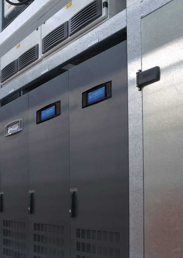
6 TS_684_IE Kohler PW 6000 S2 (160-500kVA) Technical Specification 11/01/2021UPS CONTROL PANEL
A control panel located on the front of the cabinet provides the means for day-to-day UPS operation and performance
monitoring. Two control panels are available; an LCD control panel is fitted as standard on modules up to 300 kVA, and a
TFT touch screen control panel is used on 400/500 kVA models.
Note: The TFT control panel is available as a fitted option on the lower rated models on request.
From the UPS control panel the operator can:
• Stop and start the UPS module
• Transfer the UPS output (load) between the inverter and bypass
• Monitor the UPS input/output voltage, current and frequency
• Monitor the battery charge discharge current and battery status
• Interact with monitored alarm and warning messages
• Configure the UPS operating parameters (service mode)
• Interrogate the UPS operating events and alarm history (service mode)
• Carry out diagnostic actions (service mode)
LCD Control panel
Mimic Diagram LCD Display Panel Operator Keys
The user-friendly Power Management Display provides access to all monitoring information and operator controls.
Mimic diagram
The mimic diagram contains multi-coloured LEDs that change between GREEN, RED and OFF to indicate the UPS
operation and power flow status.
LEDs LINE 1 and LINE 2 indicate the availability of the input mains and bypass mains power supplies respectively, and
are both GREEN during normal operation.
The INVERTER and BYPASS LEDs indicate which of the two power sources is providing the critical load supply. These
LEDs illuminate GREEN to indicate which of the two is the active supply source.
The BATTERY LED indicator is a solid GREEN when the battery is being charged and flashes when the battery is
discharging – e.g. when it is providing the output load power during a mains failure.
The ALARM LED, located at the lower-centre area of the Power Management Display, is a visual indication of any
monitored internal or external alarm condition. When activated, it is accompanied by an audible alarm that can be
cancelled by pressing the RESET button.
LCD Display panel
The 2x 20 character multi-function LCD Display is menu-driven using the UP, DOWN and ENTER operator keys. It provides
a simple communications interface that enables the operator to monitor important UPS operating parameters and alarm
warnings, and carry out various control operations such transferring the load between the inverter and bypass.
TS_684_IE Kohler PW 6000 S2 (160-500kVA) Technical Specification 11/01/2021 7LCD Display panel summary:
• Displays the input and output voltage, current, frequency and power
• Displays an ‘Event register’ which stores a date/time stamped history of the 99 most recent alarms
• Enables battery run time monitoring
• Enables selection of commands such as UPS Start-up and Shut-down, Load transfer between inverter and bypass
• Provides diagnostic facilities and access to UPS adjustments and testing facilities (service mode only)
Operator keys
The operator keys allow the user to:
• Start and stop the UPS and transfer the load between inverter and bypass
• Set operating parameters and adjustments via the menu driven LCD display
• Select the UPS operating voltages, currents, frequencies and other values on the LCD display
There are two ON/OFF keys located on the control panel. In order to prevent inadvertent operation, both keys must be
pressed simultaneously in order to turn the UPS OFF or ON.
TFT Control panel
The TFT control panel has a microprocessor-based touch-screen display which offers simple operation. When the UPS is
energised the display runs through an initialisation process for several seconds and then automatically turns on,
displaying the default mimic diagram screen. The screen’s back-light turns off after three minutes of inactivity and turns
back on when the screen is next touched.
Default mimic display
A UPS mimic diagram is displayed on the default screen and shows the power flow through the UPS module and indicates
its operating status – in either single cabinet or multi-cabinet configuration. This screen can be accessed from any other
screen by pressing the MIMIC icon in the display header bar.
The functional status of each block is identified by its line colour, as shown below.
• Green – In operation
• White – Inactive
• Yellow – Warning condition
• Red – Fault conditions
Three meters are included on the mimic display screen to indicate the rectifier, inverter, bypass and load operating
parameters. The meter source is selected by touching the associated power block on the mimic display. The battery
temperature and remaining autonomy time are also displayed.
8 TS_684_IE Kohler PW 6000 S2 (160-500kVA) Technical Specification 11/01/2021Display header bar
A navigation and status bar is displayed in the header area of every screen.
A B C D E F
H G
A Home Accesses the HOME screen.
B Mimic diagram Accesses the MIMIC diagram screen.
C The warning symbol is only visible in the presence of an alarm or monitored events.
Warning
Touching this icon will silence the audible alarm and open the EVENTS screen.
D Date Current date indication. Set in the user menu and used to date-stamp the alarms/events log.
E Time Current time indication. Set in the user menu and used to time-stamp the alarms/events log.
F ON/OFF Turns the UPS module ON/OFF. Requires a confirmation message to be accepted.
G Each UPS module is given a sequential number in a parallel system. The number shown here is used to
UPS number identify a particular module –e g. P01 indicates the UPS number 01.
In a single module installation this would indicate S01.
H Load Status Displays whether or not the load is protected, when the user is in the module navigation level.
TS_684_IE Kohler PW 6000 S2 (160-500kVA) Technical Specification 11/01/2021 9Home screen
The home screen is accessed by pressing the HOME icon on the display header bar on any screen and contains six icons
that provide access to subordinate control and set-up function screens.
A B C D E F
Displays a list of recently occurred events with date, time, event name, description and sequential ID number.
A Events
As a default the most recent appears on top.
B Measures This item displays a full set of measurements for each functional block of the UPS (detailed below).
In this menu, the user can change the operating mode of the UPS. Once the command is executed, the user is
C Command
immediately directed to the mimic diagram where the new status of the UPS is indicated (detailed below).
D UPS Data Gives information regarding the manufacturing of the UPS.
E User Enables the adjustment of data such as date and time, automatic battery test, etc (detailed below).
F Service This password protect area enables the service technician to adjust several UPS parameters (detailed below).
10 TS_684_IE Kohler PW 6000 S2 (160-500kVA) Technical Specification 11/01/2021CUSTOMER INTERFACE FACILITES
Each UPS cabinet is fitted with a communications interface board, as shown below, which enables various external
monitoring and control applications to be connected to the UPS to satisfy particular site requirements.
1
2
4
KEY IDENT FUNCTION
3
11 1 Modem Slot for optional Modem/Ethernet card only
2 SNMP Slot for optional SNMP card
12 3
3 JD1 RS-232 PC Interface on Sub D9 Female
4 USB RS-232 PC Interface on standard USB 4
10
8 5 JR2 RS-485 on RJ45 port. Remote panel interface 5
5 6 JR1 RS-485 on RJ45 port. Multidrop interface 11
6
6 7 X3 Customer wired inputs
8 X2 Volt-free switched alarm/status outputs
9 X1 Castell interlock function 7
10
10 JD8 For parallel bus adapter card (JD5/JD6)
2 11 SW1-9 Multi-cabinet configuration DIP switch
12 X1 Customer wired inputs
1
8
160-300 kVA 400/500 kVA
9
RS-232 and USB – Computer serial interface
An RS-232 serial interface is available through a Sub D-9-pin female socket (JD1) and a standard USB port.
JD1 provides an intelligent RS-232 serial port which, when used in conjunction with suitable software, allows continuous
monitoring of the input mains voltage and UPS status, and displays various status messages if there any UPS system
changes. JD1 can be connected using a standard computer serial communications cable with a maximum length of the
RS-232 cable is 15m.
The USB port is connected in parallel with JD1 and outputs the same data stream.
RS-485 Interface for multidrop
‘Multidrop’ is an optional feature that is only applicable in a multi-module UPS system. It allows the communications
interface board in the ‘master’ UPS cabinet to collect data and messages from those in the ‘slave’ cabinets. The received
data is then processed at a centralised point on the ‘master’ communications interface board and then output as a single
data stream on the RS-232 port (JD1), USB port, and also transmitted to the SNMP card if inserted in the relevant card-
slot.
The multidrop output data stream can be connected to a computer which, using suitable software, can then display the
operating parameters and status at both ‘system’ level and for each individual UPS module.
Multidrop is implemented by connecting a purpose-designed cable between JR2 (RJ45) on the communications interface
board in every module. If this feature is requested, the commissioning engineer will install the required kit of parts and test
the system to ensure it is fully functional as part of the UPS commissioning procedure.
TS_684_IE Kohler PW 6000 S2 (160-500kVA) Technical Specification 11/01/2021 11Dry ports – external wired input/output connections
A range of optional, hard-wired, input/output control and monitoring facilities can be connected to volt-free (dry port)
terminals. The external connections are made to Phoenix spring terminal blocks (annotated X1, X2, X3) using 0.2 mm² to
1.5 mm² cables.
All voltage-free contacts are rated at 60VAC/500mA
160-300 kVA Model interface connections
Terminal Contact Signal Display Function
X1/10 Gnd Gnd +12 Vdc Power source (max 200 mA)
X1/9 In +12 Vdc
X1/8 Gnd Gnd REMOTE SHUTDOWN
(Do not remove the factory-fitted bridge if this feature is not used)
X1/7 In +12 Vdc
X1/6 Gnd Gnd Battery Temperature Sensing
X1 (If connected this input is battery temperature dependent)
X1/5 In +3.3 Vdc
X1/4 Gnd Gnd Customer Specific Input (1)
X1/3 In +12 Vdc (Function on request))
X1/2 Out Gnd Customer Specific Input (2)
(Default NC = Generator on line)
X1/1 Gnd +12 Vdc
X2/15 Com Alarm COMMON Common
ALARM
X2/14 NC No Alarm Condition
X2/13 NO Common (System) Alarm active
X2/12 Com Status LOAD ON Common
MAINS
X2/11 NC Load not On Bypass
X2/10 NO Load on Bypass (Mains) active
X2/9 Com Alarm BATT LOW Common
X2 X2/8 NC Battery OK
X2/7 NO Battery Low active
X2/6 Com Status LOAD ON INV Common
X2/5 NC Load not On Inverter
X2/4 NO Load on Inverter active
X2/3 Com Alarm MAINS OK Common
X2/2 NC Mains not present
X2/1 NO Mains present
12 TS_684_IE Kohler PW 6000 S2 (160-500kVA) Technical Specification 11/01/2021400/500 kVA Models interface connections
All voltage-free contacts are rated at 250 Vac/8A, 30 Vdc/8A, 110 Vdc/0.3A, 220 Vdc/0.12A.
Terminal Contact Signal Display Function
X3/14 Gnd Gnd Battery Temperature Sensing
X3/13 In +3.3 Vdc (If connected this input is battery temperature dependent)
X3/12 Gnd Gnd GENERATOR Customer Specific Input (1)
OPER ON (Default NC = Generator on line)
X3/11 In +12 Vdc
X3/10 Gnd Gnd EXTERNAL O/P When used, both the external output breaker and internal IA2 have to be
BREAKER either open or closed in order to isolate or connect the UPS.
X3/9 In +12 Vdc
Display: PARALLEL_SW_OPEN or PARALLEL_SW_CLOSED
X3/8 Gnd Gnd EXT MAN BYP External Manual Bypass
X3
X3/7 In +12 Vdc (Default NC = External bypass closed)
X3/6 Out +12 Vdc +12 Vdc Power source (max 200 mA)
X3/5 Gnd Gnd
X3/4 Gnd Gnd REMOTE RSD Remote Shut Down
SHUTDOWN Leave jumper JP5 in place if no Remote Shut Down input is connected
X3/3 In +12 Vdc
X3/2 – REMOTE RSD Remote Shut Down (For external switch)
X3/1 – SHUTDOWN Max 250Vac/8A, 30Vdc/8A, 110Vdc/0.3A, 220Vdc/0.12A
X2/18 Com Common
X2/17 NC Auxiliary NO
X2/16 NO Auxiliary NC
X2/15 Com Alarm COMMON Common
ALARM
X2/14 NC No Alarm Condition
X2/13 NO Common (System) Alarm active
X2/12 Com Status LOAD ON Common
MAINS
X2/11 NC Load NOT On Bypass
X2/10 NO Load on Bypass (Mains) active
X2
X2/9 Com Alarm BATT LOW Common
X2/8 NC Battery OK
X2/7 NO Battery Low active
X2/6 Com Status LOAD ON INV Common
X2/5 NC Load not On Inverter
X2/4 NO Load on Inverter active
X2/3 Com Alarm MAINS OK Common
X2/2 NC Mains not present
X2/1 NO Mains Present
X1/2 230Vac – EXT MAN BYP Castell Interlock Function
X1 External Manual Bypass closed (230 Vac 2AT)
X1/1 N –
TS_684_IE Kohler PW 6000 S2 (160-500kVA) Technical Specification 11/01/2021 13SNMP Card slots
Simple Network Management Protocol (SNMP) is a world-wide, standardised communication protocol that uses a simple
control language to monitor and control a network-connected device via an SNMP compatible application running within a
standard web browser.
The PowerWAVE 6000 S2 communications interface board contains two SNMP slots; one is designed to house a Modem/
Ethernet SNMP adapter card and the other a Modem/GSM adapter. Alternatively, SNMP connectivity can also be
implemented using an external SNMP adapter connected to the UPS RS-232 output.
An SNMP/Ethernet adapter contains an RJ-45 connector which allows the card to be connected to a computer network
using a standard network cable. Once connected, the UPS-Management software agent, which is already installed in the
SNMP adapter, then monitors the UPS operating parameters and makes the data available to the connected network. In a
multi-module UPS system the SNMP interface can communicate ‘system-wide’ data or data for an individual UPS module.
The SNMP card enables event/alarm emails, server shut down (with optional licenses) and other tasks. The SNMP card
can also be integrated with BMS software over a local area network (LAN) for SNMP or Modbus information over IP. An
optional card enables Modbus over RS-485.
SNMP communication can also be implemented using an external SNMP adapter connected to the communications
interface board serial port, as shown in the illustration below.
External SNMP Adapter
9
Ethernet
Internal SNMP Card
INSTALLATION PLANNING
The following guidelines should be taken into account when planning a suitable UPS location and environment.
Location considerations summary
• The equipment must be installed and transported in a upright position
• The floor at the installed location and en-route from the off-loading point must be able to safely take the weight of
the UPS and battery equipment
• The floor material where the UPS is to be located should be non-flammable
• Local fire protection standards must be respected
• Ensure that appropriate power supplies are available and that UPS cabling can be performed easily
• The location must be vibration free
• If the UPS is to be installed in bayed enclosures, partition walls must be installed.
Environmental considerations summary
• Avoid high ambient temperature, moisture and humidity
Humidity (< 90% non-condensing) and temperature (+15°C / +25°C) are within prescribed limits
• A battery temperature of 20°C is recommended to achieve a long battery life
• Any prescribed air cooling flow must be available. Ensure the air conditioning system can provide a sufficient
amount of air cooling to keep the room at, or below, the maximum desired temperature
• Ensure no dust or corrosive/explosive gases are present
14 TS_684_IE Kohler PW 6000 S2 (160-500kVA) Technical Specification 11/01/2021Clearances
> 200 mm
400/500 kVA UPS 400/500 kVA UPS
160-300 kVA 160-300 kVA 160-300 kVA
> 1000 mm
> 900 mm
50-100 mm
50-100 mm
> 200 mm
400/500 kVA UPS 400/500 kVA UPS
160-300kVA 160-300 kVA 160-300 kVA
> 1000 mm
> 900 mm
The above diagram illustrates the recommended clearances to be provided around the UPS cabinets.
Notes:
1. All cables enter the UPS via the bottom of the cabinet (an optional Top Cable Entry cabinet is available for the 400/
500 kVA model) therefore no service/installation access is required from the rear or sides of the cabinets.
2. A minimum of 900-1000 mm clearance is required at the front of the cabinets for service access, and where
possible this should be increased to allow safe passage in front of the UPS with the doors open.
3. In order to gain full access to some internal components it is necessary to open the doors by slightly more than 90º.
If the cabinet is located adjacent to a partition or wall that extends beyond the front of the cabinet a clearance of
50-100 mm should be provided between the cabinet and the partition to allow the doors to open adequately, as
illustrated in the lower diagram above. Note that there is no space required between cabinets.
4. The 160-300 kVA cabinets are force-cooled by rear-mounted extraction fans which require a minimum of 200 mm
space at the rear of the cabinet to allow adequate exhaust air flow.
5. The 400/500 kVA cabinets are force-cooled by roof-mounted extraction fans. These cabinets do not require any
space at the rear of the cabinet but a minimum free space of 400 mm is required above the cabinets.
TS_684_IE Kohler PW 6000 S2 (160-500kVA) Technical Specification 11/01/2021 15UPS POWER CABLING
All power cables are connected to a row of busbars located near the bottom of the UPS cabinet, as shown. An optional
Top Entry cabinet is available for the 400/500 kVA models.
UPS Module power connections
160/200 kVA
Power connections
1L1 1L2 1L3 3N 3L2 +
PE
1/2N 2L1 2L2 2L3 3L1 3L3 N
Single
feed links
Battery
connections
250/300 kVA
Power connections
1N 1L1 1L2 1L3 3N 3L2 +
PE PE
2N 2L1 2L2 2L3 3L1 3L3 N
400/500 kVA
Power connections
1N 1L1 1L2 1L3 2N 2L1 2L2 2L3 3N 3L1 3L2 3L3 + N
Battery
connections
PE
Single/dual feed input
The UPS can be configured for a ‘single feed’ or ‘dual feed’ input connection. For a single feed input (standard), links are
fitted between the bypass mains terminals and input mains terminals and the input mains cables therefore feed both
supplies. The single feed links are removed for a dual feed input configuration and the bypass mains terminals are
connected to a dedicated bypass mains power source.
Note: Internal rear access is required to reconfigure the single/dual feed links in a 400/500 kVA model. If a 400/500 kVA
UPS cabinet is to be placed against a wall, any configuration change must be completed before it is finally positioned.
16 TS_684_IE Kohler PW 6000 S2 (160-500kVA) Technical Specification 11/01/2021FUSE & CABLE SIZING
It is the customer’s responsibility to provide all the external fuses, isolators and cables that are required to connect the
UPS inputs and outputs to their respective power distribution boards and battery system.
Input/output supply protection
The UPS input/bypass mains supply cables must be connected via an LV-Distribution board in which suitable fuses or
circuit breakers are installed to provide both overload protection and a means of isolating the UPS from the mains supply
when required. Similarly, the UPS output cables should be connected to the load equipment via a load distribution panel
containing suitable load protection devices. The input/output AC and DC cables and protective devices are identified in the
diagrams on page 18 and page 19.
The fuse and cable sizing details given in the following tables are provided for guidance only:
• The UPS must be installed to prescribed IEC or local regulations (e.g. BS7671).
• The required DC cables and battery fuses are bespoke to the installation, depending on the battery type and
quantity. Site-specific DC cable and fuse ratings can be provided by Kohler Uninterruptible Power on request.
Cabling details for a single-feed input UPS cabinet
UPS CONNECTIONS (Single-feed input)
UPS Module Rating (kVA) 160 200 250 300 400 500
Cable A 1L1,1L2,1L3,1N, PEa Max input demandb 271A 339A 424A 509A 679A 848A
Termination 5x M10 3x (5x M12)
Tightening Torque 50 Nm 84 Nm
Fuse A Agl/CB 3x 250A 350A 400A 500A 630A 800A
Cable D 3L1,3L2,3L3,3N,PEa Max rated outputc 232A 290A 361A 433A 577A 722A
Termination 5x M10 3x (5x M12)
Tightening Torque 50 Nm 84 Nm
Cable E a Max DC current Bespoke to installation
BATT+, BATT-, N, PE
Termination 4x M10 3x (4x M12)
Tightening Torque 50 Nm 84 Nm
Fuse E Agl/CB 3x 350A 450A 630A 630A 1000A 1250A
a. Protective Earth (PE) cable must be sized in accordance with local and national regulations
b. Rating shown for 380V operation at low input voltage and batteries charging. See specification for 400/415V current ratings.
c. Rating shown for 380V operation at full load @ 1.0PF. See specification for 400/415V current ratings.
TS_684_IE Kohler PW 6000 S2 (160-500kVA) Technical Specification 11/01/2021 17Single-feed input diagram
MAINS DISTRIBUTION BOARD
Mains Supply (3x380/400/415)
UPS MAINS SUPPLY
Fuse A
Cable A L1 L2 L3 N PE
1L1 1L2 1L3 1N PE 2L1 2L2 2L3 2N PE
Fuse E
F1 F2 IA3 & IA4 in
(IA3) (IA4) 400/500 kVA
Cable E
Rectifier Static Bypass Line
N N
Inverter
Static Switch Maint.
Bypass
IA 2 IA 1
PE PE
BATTERY UPS CABINET
3L1 3L2 3L3 3N PE
Cable D
L1 L2 L3 N PE
LOAD DISTRIBUTION BOARD
18 TS_684_IE Kohler PW 6000 S2 (160-500kVA) Technical Specification 11/01/2021Cabling details for a dual-feed input UPS cabinet
UPS CONNECTIONS (Single-feed input)
UPS Module Rating (kVA) 160 200 250 300 400 500
Cable B 1L1,1L2,1L3,1N, PEa Max input demandb 271A 339A 424A 509A 679A 848A
Termination 5x M10 3x (5x M12)
Tightening Torque 50 Nm 84 Nm
Fuse B Agl/CB 3x 250A 350A 400A 500A 630A 800A
Cable C a c 232A 290A 361A 433A 577A 722A
2L1,2L2,2L3,2N, PE Max bypass demand
Termination 5x M10 3x (5x M12)
Tightening Torque 50 Nm 84 Nm
Fuse C Agl/CB 3x 250A 350A 400A 500A 630A 800A
Cable D a c 232A 290A 361A 433A 577A 722A
3L1,3L2,3L3,3N,PE Max output demand
Termination 5x M10 3x (5x M12)
Tightening Torque 50 Nm 84 Nm
Cable E a Max DC current Bespoke to installation
BATT+, BATT-, N, PE
Termination 4x M10 3x (4x M12)
Tightening Torque 50 Nm 84 Nm
Fuse E Agl/CB 3x 350A 450A 630A 630A 1000A 1250A
a. Protective Earth (PE) cable must be sized in accordance with local and national regulations
b. Rating shown for 380V operation at low input voltage and batteries charging. See specification for 400/415V current ratings.
c. Rating shown for 380V operation at full load @ 1.0PF. See specification for 400/415V current ratings.
TS_684_IE Kohler PW 6000 S2 (160-500kVA) Technical Specification 11/01/2021 19Dual-feed input diagram
MAINS DISTRIBUTION BOARD
Mains Supply (3x380/400/415) Mains Supply (3x380/400/415)
UPS MAINS SUPPLY UPS BYPASS SUPPLY
Fuse C
Fuse B
L1 L2 L3 N PE L1 L2 L3 N PE
Cable C
Cable B
1L1 1L2 1L3 1N PE 2L1 2L2 2L3 2N PE
Fuse E
F1 F2
IA3 & IA4 in
(IA3) (IA4) 400/500 kVA
Cable E Static Bypass Line
Rectifier
N N
Inverter
Static Switch Maint.
Bypass
IA 2 IA 1
PE PE
BATTERY UPS CABINET
3L1 3L2 3L3 3N PE
Cable D
L1 L2 L3 N PE
LOAD DISTRIBUTION BOARD
20 TS_684_IE Kohler PW 6000 S2 (160-500kVA) Technical Specification 11/01/2021You can also read