Hydrogen The role of hydrogen storage in a clean responsive power system - An insights report by the Energy Technologies Institute

Page created by Alfred Harvey
 
CONTINUE READING
Hydrogen The role of hydrogen storage in a clean responsive power system - An insights report by the Energy Technologies Institute
An insights report by the
Energy Technologies Institute

Hydrogen
The role of hydrogen storage in
a clean responsive power system
Hydrogen The role of hydrogen storage in a clean responsive power system - An insights report by the Energy Technologies Institute
02   03   Energy Technologies Institute   www.eti.co.uk

The ETI has completed an assessment of the                Key headlines
potential of using salt caverns, traditionally
used to store natural gas, to store hydrogen
(H2) for power generation when the demand
                                                          »	
                                                            Using salt caverns to store hydrogen has the
                                                               potential to deliver clean, grid-scale load-
                                                               following energy supplies
                                                                                                                                  “ The  UK has sufficient
                                                                                                                                    salt bed resource
                                                                                                                                    to provide tens of
                                                          »	
                                                            The potential to store hydrogen changes
for electricity peaks daily. The use of these                  inflexible gasification and reforming
                                                                                                                                    ‘GWe’* to the grid
                                                                                                                                    on a load following
caverns would reduce the investment in clean                   technology into competitive, highly flexible
                                                               options for load following fossil fuel, biomass                      basis from H2
power station capacity that the nation requires                                                                                     turbines
                                                                                                                                             ”
                                                               and waste fed power stations
                                                          »	
                                                            The UK has sufficient salt bed resource to
to build, and lift the average efficiency of the               provide tens of ‘GWe’* to the grid on a load
                                                               following basis from H2 turbines
country’s responsive power system.
                                                          »	
                                                            Technologies making hydrogen from
                                                               methane, such as steam methane reforming
                                                               (SMR) and autothermal reforming (ATR)
                                                               need to improve if they are to be competitve
                                                               in power production from 100% hydrogen
                                                               storage configurations – much of this
                                                               improvement is already in hand in national
                                                               clean fossil fuel, Carbon Capture and Storage
                                                               and turbine technology development
                                                               programs
                                                          »	
                                                            Pre-combustion technology with storage
                                                               offers flexibility to produce hydrogen
                                                               and reduce the overall power generation
                                                               investments

Dennis Gammer
Strategy Manager – Carbon Capture & Storage
Email: dennis.gammer@eti.co.uk
Telephone: 01509 202010
                                                          * GWe
                                                            
                                                                = Gigawatt of electricity, GWhe = Gigawatt hours of electricity
Hydrogen The role of hydrogen storage in a clean responsive power system - An insights report by the Energy Technologies Institute
04       05   Energy Technologies Institute   www.eti.co.uk

The role of fossil fuel power stations

                                                              As the UK invests in lowering its national         After undertaking dispatch analysis, the          a gasifier (coal and/or biomass) or steam
     » New renewable power supplies                          carbon footprint, more and more renewable          ETI believes that CCS technologies have the       reformer (methane gas) runs continuously,
          are intermittent which increases                    power supplies (wind, solar) are being built       potential to show adequate flexibility in load-   feeding H2 to a salt cavern when power is not
          the need for a low cost ‘on                         and put on the grid. However, although             following mode. The main challenge for large      needed, and feeding the turbine when power
          demand’ supply                                      clean, these new supplies are intermittent,        scale roll out is the combination of:             is needed. The gas turbine (GT) is capable of
     »	
       Operating fossil fuel power stations                  which increases the need for a low cost
                                                                                                                 »	
                                                                                                                   Added capital cost for CO2 separation,         burning much more than the instantaneous
          at lower loads reduces their                        ‘on demand’ power supply that currently               compression, transportation and storage,       output of the H2 plant. The store then co-
          efficiency and increases capital                    only fossil fuel plants can satisfy. Power            which would sit idle most of the time          feeds the turbine at peak demand periods to
          costs per MWh produced                              produced from this fleet of fossil fuel plants                                                       fill the turbine capacity. Since H2 production
                                                              will diminish and eventually only plants fitted    »	
                                                                                                                   Energy losses associated with running          uses a lot of electricity, this could be optionally
     »     believes that CCS technologies
          ETI
                                                              with Carbon Capture and Storage (CCS)                 carbon capture equipment especially            increased at night when power is cheap.
          have the potential to show                                                                                at low load
                                                              will be built. Unfortunately, operating fossil                                                       The ETI appointed Amec Foster Wheeler and
          adequate flexibility in load-
                                                              fuel power stations at lower loads reduces         The ETI has evaluated configurations which        the British Geological Survey to complete a
          following mode
                                                              their efficiency (more CO2 is produced per         use hydrogen storage and turbines to see if       techno-economic study ‘Hydrogen Storage
     The role of fossil fuel power stations in                MWh) and increases capital costs per MWh           storage could reduce the cost of the idled        and Flexible Turbine Systems’ which has
     the mix of UK power production has                       produced, both of which are aggravated by          asset in a load following power system. In        informed our thinking in this subject.
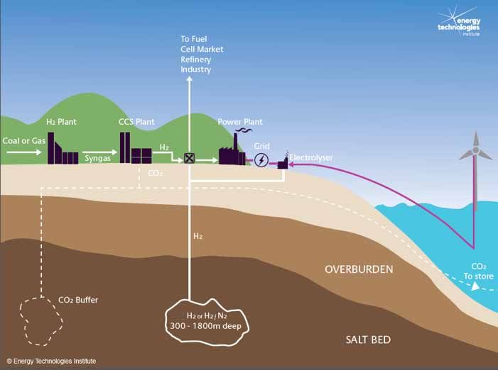
     traditionally been threefold:                            fitting CCS equipment. When run at full load,      one such configuration, shown in Figure 1,
     »     support nuclear in producing
          To                                                  stations with CCS will offer competitive clean
          base load generation at low cost                    power, but a high proportion of the power
                                                              we produce (30-40%) is in the load following       Figure 1
     »	
       To follow the changing daily                          mode. This must have low emissions if the UK
          demand for power – to load follow                                                                      Power station configurations using H2 storage
                                                              is to reach it’s 2050 climate change targets.
     »	
       To provide short bursts of power
          to cope with temporary demand                       Therefore CCS plants must eventually show          Natural
                                                                                                                 Gas        Reformer         H2 or H2/N2           GT run to
          peaks at very short notice                          similar flexibility to today’s mainstay combined              CCS –100%                              meet peak
          (minutes)                                           cycle gas turbine (CCGT) products, which strive               load                                   demand
                                                              for good start up and low load performance                                                                          Power
                                                              characteristics in addition to ever higher         Coal
                                                              efficiencies. Coal stations have also developed    Biomass    Gasifier
                                                              flexibility, with the exception of gasifiers                  CCS –100%
                                                                                                                            load
                                                              (Integrated Gasification Combined Cycle –                                      C02
                                                              IGCCs) which cannot be ramped up quickly                                                                            The most expensive assets (gasifier,
                                                              and have a limited ability to operate                                                                               reformer, CCS) all ‘sweat’ at 100% load
                                                                                                                 ASU                 C02 to CCS                                   and peak efficiency, even though power
                                                              at low load.                                                           Store 100%      Hydrogen
                                                                                                                                                     salt cavern                  production varies.
                                                                                                                                     load
Hydrogen The role of hydrogen storage in a clean responsive power system - An insights report by the Energy Technologies Institute
06      07      Energy Technologies Institute       www.eti.co.uk

H2 storage in salt caverns

»	
  Salt caverns are man-made underground                                Salt caverns are man-made underground              In Germany2 air is compressed overnight                                               Figure 2

       holes created by washing salt out of                             holes created by washing salt out of large         and pumped into a salt cavern to feed a gas                                           Creating a salt cavern
       large geological structures made of                              geological structures made of almost pure          turbine which supplies power at peak times
       almost pure salt                                                 salt. As shown in Figure 2 a well is drilled       during the day. This demonstrates the ability
                                                                        down into the salt field. Water is pumped          of a cavern to operate in a ‘daily’ filling and
»	
  Used throughout the world to store natural
                                                                        down, dissolves the salt, and the brine            emptying mode. Several gas stores in the UK
       gas and other hydrocarbon products
                                                                        removed for use or disposal. They are used         can also release very large flowrates of gas to
» Viable stores exist in the UK at                                     throughout the world to store natural gas          the grid to meet peak demands.
       various depths, down to more than                                and other hydrocarbon products. The UK
       2000 meters deep                                                                                                    Most stores are operated by filling them to
                                                                        stores about 10,000 GWh of natural gas             a pressure, usually 80% of the surrounding
»	
  UK’s largest caverns are over                                        alone (enough to keep the country running          rock formation pressure, and then reducing
       600,000m3                                                        for a few days). H2 is also currently stored in    pressure by the removal of gas to a minimum
                                                                        a small number of salt caverns in the UK and       of about 30% of the formation pressure.
                                                                        the USA, supporting chemical plants and oil        Formation pressures vary with store depth,
                                                                        refineries. The largest single store (USA) holds   with viable stores in the UK more than 2000
                                                                        over 100GWh of H21.                                meters deep at pressures over 270 Barg.
                                                                                                                           The cavern size and shape can be restricted
                                                                                                                           primarily by the salt thickness. The UK’s
                                                                                                                           largest caverns are about 600,000m3
                                                                                                                           (e.g. 100m diameter by 100m high)3.

                                                                                                                                                                                                                 Courtesy BGS

600,000m3
 he UK’s largest caverns
T
are over 600,000m3

1
    Hydrogen as energy storage medium and fuel for transport, U Bunger, Trondheim 2012                                    2 
                                                                                                                               Crotogino, Fritz, Klaus-Uwe Mohmeyer, and Roland Scharf. ‘Huntorf CAES: More than 20 Years of Successful Operation.’
                                                                                                                               Natural Gas 45.50(2001):55
                                                                                                                           3
                                                                                                                               Memorandum submitted by British Geological Survey www.parliment.uk
08   09    Energy Technologies Institute   www.eti.co.uk

                                                                                                                   Figure 3

                                                                                                                   UK salt fields shown in yellow, Triassic (top) and Permian                   Courtesy BGS

The UK resource

»	
  Over 30 large caverns in use in the UK                  Fields of different depth were chosen
                                                           because as depth increases, the storage
»	Detailed analysis of UK salt fields are
                                                           pressure increases. This means the stores can
     available
                                                           hold more gas, but expensive compression
»	
  The peak demands of a whole city could                  equipment is needed to pressurise the gas
     be catered for by a single cavern                     into the cavern.
»	
  Caverns have a long successful history in
     several different storage roles including             Screening work revealed that for the
     seasonal, diurnal, and rapid response and             shallowest salt bed (Teesside) a large number
     handling various liquids and gases,                   of stores (about 20) would be needed to
     including H2                                          fill a large turbine (a gas turbine and heat
                                                           recovery steam generator (HRSG) set rated
»	
  Stores are of impactful size both for ‘on
                                                           at c.400MWe) operating at a load factor
     demand power’ and providing ‘reserves’
                                                           of 36%. A load factor of 36% was taken as
»	
  Salt beds are not widespread, but are                   representative of a station running during
     located in good locations                             the working day, but off at night
                                                           and weekends.
There are over 30 large caverns in use in the
UK spread over several locations, principally              In the deepest salt bed modelled by the ETI
in those areas shown in yellow in Figure 3.3               (East Yorkshire) a single cavern could satisfy
BGS have provided a detailed analysis of the               the turbine and HRSG. In fact a set of six
salt deposit thickness, depth and quality (in              caverns holding H2 (and Nitrogen (N2) used
terms of intrusions of ‘layers of impurity’ in             to control combustion) could hold 600 GWh
the salt bed) of these and smaller deposits. It            of H2, yielding approximately 150 GWhe of
should be noted that within the areas shown                energy accessible on a seasonal basis or 30
in yellow the bed thicknesses vary greatly.                GWhe available on a daily basis (comparable
Considerable additional capacity is currently              to all our current pumped hydro storage
being planned.                                             systems). The peak demands of a whole city

                                                                                                                                                                                30
                                                           could be catered for by a single cavern.
Three areas were selected for techno-
economic modelling:

 1     A shallow field in Teesside
                                                                                                                                                                                There are over 30 large
 2     A deep field covering East Yorkshire                                                                                                                                     caverns in use in the
                                                                                                                                                                                UK spread over several
 3     An intermediate field such as in Cheshire                             Memorandum submitted by the British
                                                                           3                                                                                                   locations
                                                                             Geological Survey www.parliment.uk
10    11      Energy Technologies Institute            www.eti.co.uk

Converting fossil fuel to H2 and
burning H2 for power

»	
  H2 manufacture is a mature technology                                     Power is produced from coal (and optionally       (with CCS) incurs an additional efficiency                              Nitrogen is usually available as a byproduct of
                                                                             biomass) using a number of different              penalty, stemming largely from losses in                                oxygen production (from air) which is needed
»	Making H2 from coal (optionally mixed
                                                                             technologies:                                     converting the methane to H2 and purifying it.                          for partial oxidation of the fuel, but in the
     with biomass) and then combusting the
     H2 causes no cost or efficiency penalty                                 »	
                                                                               Combusting coal in air, raising steam and      Therefore, unless the H2 producing schemes                              schemes shown in Figure 1, H2 use has been
                                                                                  expanding the steam in a steam turbine       get revenue from supplemental H2 sales (say                             decoupled from N2 production and so N2 has
     difference compared to conventional
                                                                                                                               for transport or chemicals) the next set of gas                         to be stored. Steam is also an effective diluent,
     power production                                                        »	
                                                                               Combusting coal in oxygen, raising steam
                                                                                                                               fired power stations, supported by Contracts                            with some advantages for a load – following
»	
  Making H2 from methane and then                                               and expanding the steam in a steam
                                                                                                                               for Difference (CFDs), will favour designs                              unit, but might increase maintenance costs of
     combusting the H2 adds cost and                                              turbine
                                                                                                                               which are designed to burn methane, not                                 the plant.
     causes a loss in efficiency compared to                                 »	
                                                                               Creating H2 from coal by reacting it with      H2. However, the transitional pathway to
     ‘conventional’ clean power production                                        a limited amount of oxygen (termed                                                                                   Recognising that cheaper and more efficient
                                                                                                                               introduce H2 from any new H2 plants may be                              H2 turbines would improve the economics
     (CCGT/CCS)                                                                   ‘gasification’) and then burning that H2     straightforward as some of the existing                                 of gasification – technology sums in excess
»	
  Impactful technology improvements                                              in a gas turbine                             and new ‘methane’ fleet will be able to burn                            of £100M4 are going into development
     are being tested in the US and Europe                                   In a world where CCS has to be fitted to          H2/methane mixtures. Currently the ETI is                               and improvement programmes. Vendors
»	
  For 100% H2 combustion, N2 or steam                                       coal stations, there is no cost penalty in the    operating a 4MW test unit to explore the safe                           are approving use of their GTs with modest
     diluent is needed. This increases                                       gasification route (H2), either in capex or       working envelope of machines firing gases                               amounts of H2 in the fuel (c.25%), and
     complexity                                                              efficiency. This is because all three routes      which contain high levels of H2.                                        improving existing designs to cope with
                                                                             from coal to power as described have similar      With regards the use of natural gas in                                  higher H2 content fuels. Several, however,
                                                                             efficiencies, about 35%* in converting the        power generation with CCS, recent R&D                                   start up with methane and switch to H2 when
                                                                             energy in coal to electricity. The gasification   and demonstration units have narrowed                                   stable. Similarly, highly efficient processing
                                                                             plant is less flexible than the combustion        the gap between pre-combustion and post                                 and separations are being explored and tested
                                                                             route, as both the gasifier and its oxygen        combustion technologies, but many of these                              e.g. by the European ‘Cachet 1 & 2’
                                                                             supply plants can change output at only a         integrate the turbine and H2 plant and so                               natural gas processes and US DOE clean
                                                                             few percent per minute, so are not good load      cannot be used in a plant such as shown in                              coal programs5.
                                                                             followers, and in any case do not turn down       Figure 1.
                                                                             to low loads easily.
                                                                                                                               H2 is a much more reactive fuel than methane,
                                                                             In today’s market, power produced from            with a very high flame velocity. Therefore
                                                                             methane gas uses CCGT technology and these        machines designed for methane but burning
                                                                             plants can also be fitted with post combustion    100% H2 rely on dilution of the H2 with N2 or
                                                                             CCS and still retain a high efficiency of 50%.    steam to control combustion.
                                                                             With today‘s technology, making H2 as a
                                                                             intermediate in a reformer or partial oxidiser

* A
    ll efficiencies quoted are based on the lower heating value of the fuel – i.e. LHV                                        4
                                                                                                                                   www.netl.doe.gov/publications/proceedings/10/utsr/presentations/tuesday/Dennis.pdf
                                                                                                                               5
                                                                                                                                   Cachet 11 Report Summary at http://cordis.europa.eu
12   13    Energy Technologies Institute   www.eti.co.uk

Economics of different power
production methods using H2

»	
  Viewed from a high level there is no clear              A table of the main statistics for the studied     quickly, as almost the entire capital spend is                         A desktop review of fuel cells technology as
     winner for fuel or technology choice on a             technologies assessed are provided in              apportioned to diminishing production.                                 an alternative to turbines concluded that
     100% load, no store option basis                      Appendix 1. The capital and efficiency             In the modelling, no correction was made for                           the cost and performance of these does not
                                                           advantages normally enjoyed by methane             the deterioration in capture efficiency with                           yet match the turbine, even though load
»	
  At lower loads (and certainly less than
                                                           over coal are compromised by the oxygen            reducing load so the results flatter the CCGT/                         following characteristics may be good. Several
     40%) the configuration with stores is
                                                           production, storage and H2 manufacture.            CCS. However, systems with the store had                               thousand alkali fuel cells, for example, would
     cheaper
                                                           When N2 is used as a fuel diluent for the          better financials at low load, as most of the                          be needed to match the turbine output, and
»	
  The gas price largely determines the                   turbine, the autothermal reforming route           assets in this configuration are still ‘sweating’,                     these need to be stacked and manifolded with
     break point at which the H2 and storage               (ATR) shows a decisive efficiency improvement      with the exception of the turbines. The only                           low pressure, exceptionally pure H2.
     combination becomes the better option.                over steam methane reforming (SMR) (41% c.f.       technology in this set that is novel is the oxy-                       Solid oxide fuel cells, using hydrocarbon feeds
     For the coal/biomass option fuel is a                 33%). However, when in the steam reforming         membrane, shown by the red line, which uses                            and operating at high temperature, seem
     relatively smaller contributor to overall             case the H2 fed to the turbine is diluted with     novel membranes to improve performance, as                             to offer more scope for good power cycle
     cost                                                  steam, not N2, the cost of the air separation      pursued by Europe’s FP7 ‘Cachet’ projects.                             efficiencies.
»	
  The ability to dilute the H2 with steam                unit and N2 storage could be eliminated and
     rather than N2 is an important option for             the SMR became competitive. Today, most of
     all GTs – further work is needed to explore           the world’s H2 is made from steam methane
     how this improves flexibility and LCoE at             reforming, due to ease of supply, operation,       Figure 4
     low loads                                             lower environmental issues and cost, but
                                                           adding CCS to SMRs erodes their advantage.         Levelised cost changes with load factor
»	
  As loads drop, aero derivatives and open
     cycle machines will become cost effective             Other sources of H2 such as electrolysis cannot                400
     for H2 fuelled GTs                                    compete on a pure cost basis with H2 from
                                                                                                                          350
                                                           fossil fuel with CCS. Only under conditions
»	
  A full dispatch analysis is needed to                                                                                 300
                                                                                                                                                           CCGT with CCS
                                                           where an installed system can produce                                                           (blue dots)
     tune findings
                                                           electrical power which has no market value                     250

                                                                                                             LCOE £/MWh
The costs of converting coal, coal/biomass and             (possibly due to excess wind and solar power                   200
natural gas to H2 with CCS and then power                  being available at times of low demand) and
                                                                                                                          150
have been produced by Amec Foster Wheeler                  has high availability to load up electrolysers
                                                                                                                                                                                                                  Coal IGCC (£74/te)
to provide ‘order of magnitude’ capital and                can the costs to manufacture H2 from power                     100
                                                                                                                                                                                                                  CCGT Base (1.9p / kWh)
                                                                                                                                    IGCC with
levelised cost. When viewed from a high level,             and water be competitive.                                      50        H2 store (solid                                                               CCGT (2.5p / kWh)
                                                                                                                                    black line)
                                                                                                                                                                                                                  OxyMembrane (1.9p / kWh)
there is no clear winner for fuel or technology            In Figure 4 the system costs are compared                       0
                                                                                                                                0     10       20     30   40    50      60     70   80    90   100   110
choice on a 100% load, no store option basis.              with the incumbent CCGT technology, fitted                                                           Load Factor %
For mid-point ‘UK’ (Department of energy and               with post combustion CCS. At high turbine
Climate Change) primary fuel prices, the solid             loads this is the best option for methane, but
                                                                                                              CCGT with CCS is compared to an IGCC with a H2 store.
fuels have a slight levelised cost advantage.              as the load drops the levelised costs increase     ‘Oxymembrane’ means H2 from methane by precombustion,
                                                                                                              with separation assisted by membrane (Cachet as noted above).
                                                                                                              Fuel price assumptions shown in brackets. Detailed assumptions in Appendix 1.
14      15      Energy Technologies Institute       www.eti.co.uk

The economics of the salt caverns

»	
  Onshore cavern costs are modest                                 smaller stores could still participate in clean   gas’ and is capitalised. For slower removal         Figure 5

       compared to other cost blocks in the                         technology options for example by storing         rates, higher pressure ranges are technically
                                                                                                                                                                          Distribution of principle
       system                                                       synthetic natural gas made from biomass           acceptable and over 50% of the cavern
                                                                                                                                                                          costs for different stores
                                                                    or waste (natural gas has about 5 times the       pressure may be useable. The deeper caverns
»	
  A 300,000m3 fast fill cavern in Yorkshire
                                                                    energy density of H2).                            studied could offer reasonable longer term
       costs about £200m, most of which is                                                                                                                                Yorkshire, 1800m deep
                                                                    By contrast the deep stores have very high        storage costs, as the surface facility cost would
       surface facilities
                                                                    topside costs to compress the H2 from 20-60       reduce and the working volumes would be a
»	
  Offshore caverns are markedly more
                                                                    Barg up to the storage pressure of 270 Barg.      higher percentage of the cavern volume.
       expensive than onshore ones. Only if very
                                                                    They incur losses as the gases are spilled and    The largest element of the ‘underground’ costs
       large quantities of storage is required (e.g.
                                                                    turbo expanded down into the turbine. This        of cavern construction is construction of the
       the Gateway proposal6 in Merseyside)
                                                                    round trip causes an expensive 2.5% (LHV)         well, so caverns tend to be the largest possible
       would these be especially attractive
                                                                    hit, in a scheme which is about 35% efficient     size feasible within the salt structure.
»	
  The shallow, thinner ‘Teesside’ field is                         (LHV). There are currently no high pressure
       borderline as a location for a H2 store for                  expanders on the market to completely
       a large power installation due to the large                  elimate this loss. The Cheshire caverns are
       number of caverns needed, and the area                                                                                                                             Cheshire, 680m deep
                                                                    arguably a good compromise.
       of land needed for development
                                                                    With today’s GT’s the need to dilute the H2
The three fields examined by the ETI research                       with N2 doubles the cavern cost contribution,
have very different depths (and so different                        which is significant but not fatal to the
storage pressures) and have different store                         economics. Even at low turbine utilisations
sizes due to salt thickness and depth. The                          and with N2 co-storage the caverns cost less
cost structures are very different in their                         than half of the turbine costs.
makeup, but the total costs are very similar.                       Fast filling and emptying stresses the walls
As shown in Figure 5 and Appendix 2, the                            of the cavern, and the pressure range and
costs of shallow stores are dominated by                                                                                                                                  Teesside, 370m deep
                                                                    annual turnovers are restricted to reduce this.

                                                                                                                      £200m
cavern construction costs, and have lesser                          For ‘daily’ operation for example, only 10% of
‘surface facility’ equipment. These would be                        the cavern pressure (or 10% of the volume,
expensive ‘strategic storage,’ requiring an                         termed the ‘working volume’) may be useable
infeasible number of caverns for ‘monthly’                          each day. The remaining 90% of the gas which
regimes. Nevertheless these                                         has to stay in the cavern is called ‘cushion      A 300,000m3 fast fill
                                                                                                                      cavern in Yorkshire
                                                                                                                      costs about £200m,
                                                                                                                      most of which is
                                                                                                                      surface facilities                                       Surface facilities
                                                                                                                                                                               Cavern
6
    The Gateway Project at http://www.gatewaystorage.co.uk                                                                                                                    Pipe
16    17      Energy Technologies Institute   www.eti.co.uk

Benefits to the energy system

»	
  H2 storage and turbines could offer                        ESME continues to build and use them out                     Figure 7

     significant system level cost benefits over              to 2050. CCGT with CCS retains leadership
                                                                                                                           H2 storage and a clean, responsive power system
     other storage approaches and reduce the                  operating at higher load factors, as expected
     cost of the clean new capacity needed by                 from a simple levelised cost analysis. The
     the UK to meet its emission targets                      modelling shows the increasing need and
                                                              value for flexibility in the system as nuclear
The potential role for hydrogen stores in the                 and wind are deployed out to 2050. A market
power sector can be illustrated by including                  which rewards this flexibility is needed to
the option in the ETI’s energy system                         reflect this requirement. In scenarios with
modelling (ESME)7 tool – a national energy                    higher intermittent generation, the demand
system design and planning capability.                        for H2 turbines grows to around 20GW.
ESME works out the mix of technologies                        Smaller quantities of H2 are fed to industry
which enables the UK to comply with its                       and possibly also the transportation sector for
2050 climate change targets at the lowest                     use in fuel cell vehicles. ESME favours biomass
cost. When the cost figures provided by this                  in the feedstock for H2, in spite of the extra
exercise were fed into ESME, H2 stores were                   costs, because in effect CO2 is removed
adopted by 2030.                                              from the air and the CCS is burying it –
The stores run at moderate load when new,                     effectively producing ‘negative emissions’
but over time the load factors are reduced.                   for power production.

Figure 6
                                                                               Geothermal plant (EGS) Electricity & Heat
ESME starts to build H2 turbines by 2030,                                      Tidal stream
                                                                               Hydro power
and continues to build them thereafter
                                                                               Micro solar PV
                                                                               Onshore wind
     140
                                                                               Offshore wind
     120                                                                       H2 turbine
                                                                               Waste gasification to power with CCS
     100                                                                       Incineration to waste                       Optional CO2 buffer storage is shown, to levelise any changes in CO2 supply to the store caused by other users.
                                                                               Biomass fired generation
     80
                                                                               Nuclear
GW

     60                                                                        CCGT with CCS
                                                                               CCGT
     40                                                                        OCGT
                                                                              Interconnectors
     20

      0
             2010       2020    2030     2040      2050
           (Historic)
                                                                     7
                                                                         http://www.eti.co.uk/project/esme/
18   19    Energy Technologies Institute   www.eti.co.uk

Appendix 1                                                                                Appendix 2
Summary of performance                                                                    Cavern capital costs for 400 MWe (gross)
of power generation via H2                                                                GT and HRSG at 36% turbine load factor

 Technology              H2 plant capex        Efficiency     LCOE 36% Load   LCOE 100%                                                                 Onshore                Offshore
                         (no storage, no       (no storage)   (as a power     Load                                                           Teesside   Cheshire   East        East Irish
                         contingency)                         plant)                                                                                    Basin      Yorkshire   Sea
                         Million £                            £/MWh           £/MWh       Salt Cavern storage size               m3          70,000     300,000    300,000     300,000

                                                                                          Salt cavern depth                      m           370        680        1800        680
 Coal Gasification       1230.4                34.4           136.8           77.4
                                                                                          Salt cavern operating pressure         bara        45         105        270         105

 Coal/Biomass            1246.5                33.9           143.1           85.7        Number of cavern required for                      21         3          1           3
 Gasification                                                                             weekly operational mode and with
                                                                                          combined storage
 ATR                     1176.2                41.12          147.4           93.5
                                                                                          Water / Brine pipeline length          km          5          61         5           1

                                                                                          Costs
 SMR                     741.84                33.1           160             105
                                                                                          Jack-up drilling rig hiring cost       Million £   –          –          –           5.2

 SMR w/Steam             717.35                35.77          151.5           97.8        Specialist drilling equipment hiring   Million £   –          –          –           1.2
                                                                                          cost
                                                                                          Geological survey cost                 Million £   3.0        3.0        3.0         6.0
 CCGT with CCS                                 48.8           140             74.1
                                                                                          Salt cavern construction cost          Million £   128.5      39.3       26.8        39.3

                                                                                          Water pipeline cost                    Million £   2.7        33.2       2.7         0.5
Gas Price 1.9p/kWh
Coal Price £74/te                                                                         Brine pipeline cost                    Million £   2.7        33.2       2.7         0.5
Biomass Price £120/te
                                                                                          Costs of a 4 legged tower              Million £   –          –          –           18.8
Project Life – 30 years                                                                   ‘Jacket’ structure
Salt Cavern Location – Yorkshire
Number of Gas Turbines – 4 for 1.3GWe                                                     Install cost of topside and            Million £   97.1       130.2      205.9       350.8
Storage Type – Co-storage of H2 and N2                                                    above ground facility
CO2 Disposal Cost £10/te                                                                  Land costs (5%)                        Million £   11.7       11.9       12.1        20.8
Contingency 25%
                                                                                          Owners costs (10%)                     Million £   23.4       23.9       24.1        41.6

                                                                                          Contingency (25%)                      Million £   58.5       59.7       60.3        104.0

                                                                                          Cost of production of                  Million £   1.4        1.8        2.2         1.8
                                                                                          cushion gas
                                                                                          Total project cost                     Million £   329.0      336.4      339.9       590.5
Energy Technologies Institute
Holywell Building
Holywell Way
Loughborough LE11 3UZ

www.eti.co.uk

© 2015 Energy Technologies Institute
You can also read