PCIM Europe Insights - Mesago Messe Frankfurt GmbH
←
→
Page content transcription
If your browser does not render page correctly, please read the page content below

PCIM Europe
Insights
Issue October 2018
Best Paper Award E-Mobility
Highly Integrated Two-Phase SiC Boost Automotive Qualification Routines
Converter with 3D-Printed Fluid Coolers for Power Electronics’ Modules in
and 3D-Printed Inductor Bobbins Electrified Powertrains
pcim-europe.com 1
Table of contents
Insights Issue October 2018
3 7
Young Engineer Award
E-Mobility 25 kW high power resonant inverter operating
Trends in EV charging research at 2.5 MHz based on SiC SMD phase-leg
modules
4 8
E-Mobility
Organizer Info
Automotive Qualification Routines for
New e-mobility approach at the
Power Electronics’ Modules in Electrified
PCIM Europe 2019
Powertrains
5 Energy Management
Standardization in Multi-Level-Converter
Submodules
6
Imprint
Mesago Messe Frankfurt GmbH, Rotebühlstr. 83–85, 70178 Stuttgart, Tel.: +49711-61946-0, Fax: +49711-
Best Paper Award 61946-98, e-mail: info@mesago.com, www.mesago.com • Register Court: Local court Stuttgart, HRB
Highly Integrated Two-Phase SiC Boost Stuttgart 1 33 44 • VAT-Identification Number: DE 147794792 • Executive Management: Petra Haarburger,
Converter with 3D-Printed Fluid Coolers Martin Roschkowski • Vice president: Lisette Hausser • Editor: Mesago Messe Frankfurt GmbH / Jochen
Koszescha, Mail: info@koszescha.de • Reader Service: Sophie Pfauter, Tel.: +49711-61946-26, e-mail:
and 3D-Printed Inductor Bobbins sophie.pfauter@mesago.com • Design: feedbackmedia.de • Publication frequency: biannual
© Copyright: Mesago Messe Frankfurt GmbH, 2018, Stuttgart.
Despite careful checks by the editorial team, no responsibility can be assumed for the accuracy of the publication. The newsletter and its contents are protected by copyright. Any usage outside of the copyright limitations requires the prior consent of Mesago Messe Frankfurt GmbH. With the acceptance
and publication of the script, the full and sole usage rights are transferred to Mesago Messe Frankfurt GmbH without restrictions on region, time or content. This encompasses the publication in all types of print media, as well as corresponding reproduction and circulation, the right to electronic use,
and publishing in all types of data networks and media. It also covers the transfer of the above-mentioned rights to third parties. Contributions bearing the name or symbol of the author do not necessarily represent the opinion of the editors. No responsibility is accepted for unsolicited submissions.
pcim-europe.com 2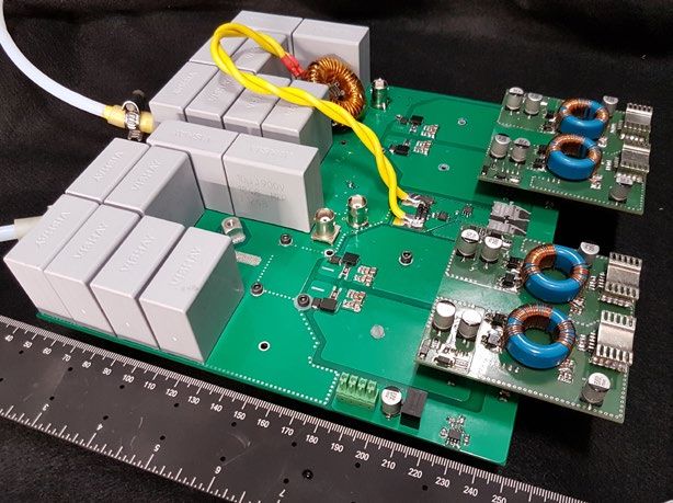
Insights Issue October 2018
E-Mobility // Trends in EV charging research
Fig. 1: Topology of power converter
Charging infrastructure for electric vehicles will be the can be used as an energy storage unit for the PV and technology uses electromagnetic energy transfer be-
key factor to ensure a smooth transition to e-mobility. reduced energy and peak power demand on the grid as tween loosely coupled charge-pads, which are placed
It is here that five technologies will play a vital role the EV charging power is locally generated from PV. with an air-gap in between. A block diagram of such
in the EV charging infrastructure: smart charging (in- With respect to (ultra)fast charging, new EVs are de- a system is shown in Figure 3.
cluding vehicle-to-grid V2G technology), charging of signed to withstand high power and new standards
EVs from photovoltaic panels, (ultra)fast charging, are being developed with 350 kW charging for the EU
contactless charging and on-road charging of EVs. market. Research on what the fast charger architec-
With the use of smart charging, the EV charging ture is and power electronic components, which give
power and direction can be continuously controlled. the most competitive advantage considering the prod-
Smart charging of EVs can provide several benefits uct development (cost, manufacturing, operability,
to the EV owner, and to the pro compactness, power effi- Fig. 2: Modular multiport fast DC charger for simultaneous
charging of multiple EVs
viders of the EV charging infra
structure such as reduced peak
» Inductive Power transfer will ciency, etc.) is being con-
ducted. The new research
demand on the grid and reduced cost. be the key element for charging question raised is how to
In order to ensure that the use of self-driving cars. « maximize the utilization of
electric vehicles results in net zero installed power of the EV
CO2 emissions, it is important that the charging infra- charger. Therefore a concept of a multiport, flexible
structure derives all/majority of its power from renew- and intelligent fast charger which features multiple
able energy sources. It is here that the falling costs of output charging spots through the implementation of
photovoltaic panels (PV) over the years and the ease multiplexing techniques, scheduling and simultaneous
of integrating into the distribution network play a key charging is developed (see Figure 2).
role. Workplaces like office buildings and industrial Contactless charging of EVs using Inductive Power
areas are ideal to facilitate solar EV charging where Transfer (IPT) and on road charging is a technology
Prof. Dr. eng. Pavol Bauer,
the rooftops and car parks can be installed with PV that is increasingly becoming acceptable as an im- Delft University of Technology
Fig. 3: Block diagram of an EV IPT based system highlighting
panels. There are several additional advantages of portant feature of autono-mous charging and a key the various power conversion stages
charging EVs from photovoltaic panels: The EV battery element enabling autonomous driving of EVs. This
pcim-europe.com 3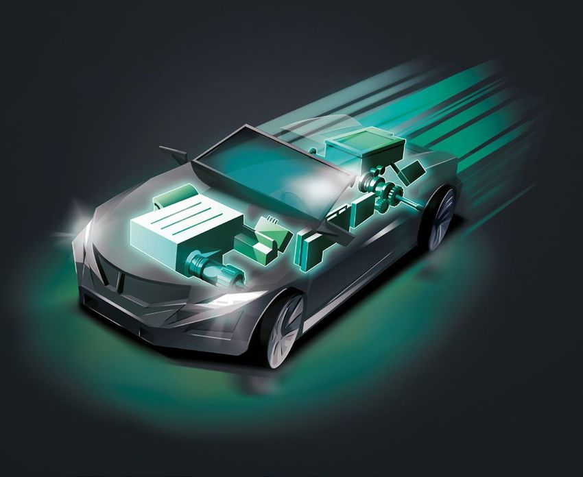
Insights Issue October 2018
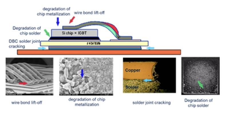
E-Mobility // Automotive Qualification Procedure for
Power Electronics Modules in Electrified Powertrains
Large-scale electro mobility in terms of (plug-in) e xtended economic impacts, like the provision of trains. Technological progress and its accompanying
hybrid electric vehicles ((P)HEVs) or pure electric vehi- preventing measures against windfall gains under demands will be considered further on by the ongoing
cles (EVs) on the road, has now become obviously opportunistic behavior. An example to note here is the activity in the ECPE working group. For instance, mod-
visible on the horizon. More and more global regions, intentionally performed utilization of underqualified ifications in the testing routines’ descriptions while
especially in Asian markets, have transformed their components in higher performant applications with using wide-band-gap semiconductors in power mod-
car mobility propulsion systems from combustion en- the aim to save costs in product assembly and ules are expected.
gines to electrified power trains. Therefore, technol- its development process. Hence, the commitment and
ogy capability, assessment and validation measures usage of qualification standards and routines are [1] Innovative Power Semiconductors and their Module integra-
tion for EV/HEV Inverters, M. Thoben et.al, 13. Symposium: Fig. 1: Typical wear out mechanisms in power modules due to power
within the development process towards large-scale meaningful and beneficial. Hybrid- und Elektrofahrzeuge, February 2016, Braunschweig, cycling (1)
mass production of power electronics powertrain It is within these boundaries that the new ECPE work- Germany
[2] Qualification of Power Modules for Use in Power Electronics
components are needed; comparable to that of tradi- ing group »Automotive Power Module Qualification Converter Units (PCUs) in Motor Vehicles, ECPE Guidline
Guideline (AQG 324)« started its work just few months AQG 324, April 2018, www.ecpe.org
» The usage of the ECPE AGQ 324 ago in 2017. 55 power electronics fellow experts from
Character-
izing
QC-01 Determination of parasitic stray inductance (Lp)
QC-02 Determination of thermal resistance (Rth value)
d ocument within the customer- 30 ECPE member companies generated a uniform module QC-03 Determination of short-circuit resistance
testting
bracket of qualification routines for multi-chip power QC-04 Insulation test
supplier-relationship will support modules in later automotive usage. The descriptions
QC-05 Determination of mechanical data
markets’ and customers’ acceptance. « of routines comprise characterizing module testing,
Environ-
mental
QE-01 Thermal shock (TST)
QE-02 Contactability (CO)
environmental testing and lifetime testing. Especially testing QE-03 Vibration (V)
QE-04 Mechanical shock (MS)
tional Electronic Control Units (ECUs) from the com- the validation of the power cycle lifetime curves of the
Lifetime QL-01 Power cycle (PCsec)
bustion era. selected power module technologies under short-time testing QL-02 Power cycle (PCmin)
The way to markets’ and customers’ acceptance of pulses (PCsec) and long-time pulses (PCmin) are of QL-03 High temperature storage (HTS)
QL-04 Low temperature storage (LTS)
innovative new techniques, technologies and techno- particular interest.
QL-05 High temperature reverse bias (HTRB)
logical systems skirts along many functional and The usage of the ECPE AGQ 324 document within the
Dr. Martin Rittner, QL-06 High temperature gate bias (HTGB)
quality issues, e.g. operational safety, manufacturing customer-supplier-relationship will support markets’ Chairman ECPE WG »AQG 324« QL-07 High humidity high temperature reverse bias (H3TRB)
yields and reliability over lifetime. Furthermore, and customers’ acceptance of all technology solutions Fig. 2: Characterization module testing, environmental testing and
all technical tasks and issues are accompanied by and new mobility concepts under electrified power lifetime testing from AQG 324 (2)
pcim-europe.com 4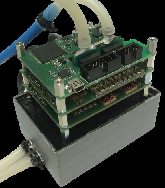
Insights Issue October 2018
Energy Management // Standardization in
Multi-Level-Converter Submodules
The world’s growing demand for electrical energy tions appear quite similar at first glance, but have The plan is to provide such submodule family
needs a new concept to ensure a reliable and also never been harmonized in terms of interface or members for the global market with centralized
flexible power scaling. Today systems from HVDC rack-mounting compatibility. This leads to a variety perfective maintenance and quality and quality
to STATCOM are provided by a few big players. in non-compatible mechanical outlines. If we addi- management which will form a downward com
For scalable high power applications up to the giga- tionally consider reduced product life cycles in high patible MMC submodule standard.
watt-range they all use the principle of modular voltage IGBTs, which follow the 600 V to 1700 V IGBT
multi-level converters (MMC). Such systems are Chip and packaging technology mainstream, this
based on submodules, mostly voltage source half-, principle will lead to an immense amount of vari-
or full-bridge topologies. From up to several tens to ants. Keep in mind that each version has to provide
thousands of such »megawatt-submodules« are ar- spare parts for several ten Years, which will be a Fig. 1: Standardized Interface, arranged along one side of
the Submodule, power scaling by Z-, or Y-axis
ranged side by side in converter halls, similar to real challenge because downward-compatibility was
bricks in a wall. The basic functionality is never a design issue.
always the same; the design varies in » … it will be a At the PCIM Europe 2018, a new
small details depending on the provider. game-changer… « approach was presented in coop-
Comparing existing designs we identified [a PCIM 2018 visitor] eration between Fraunhofer IISB
that they all appear very similar, but not and an independent industrial
good for a future-up-scaling. Enhancing power will partner. The Fraunhofer IISB has a long term exper-
lead to more and more »hard-to-handle« mechanical tise in the field of MMC submodule design.
concepts while their aspect ratio will run into an Based on a family platform idea this approach pro-
undesirable direction. Spare part exchange time – vides identical interfaces and same rack design for
a major system cost aspect – will increase as a various IGBT voltages and topologies. A much better
consequence. form factor will guarantee not only a volume neutral
A similar design pattern within such players is obvi- power enhancement for future generations, but also
Markus Billmann,
ous; but all observed modules seem to be »devel- a nearly ideal mounting space for power electronics Fraunhofer Institute IISB
oped for an actual demand«, not considering common components. The design also introduces water cool-
Fig. 2: Very simple Rack mounting and
future aspects. This means various MMC genera- ing for key components as the main capacitor. minimized service time
pcim-europe.com 5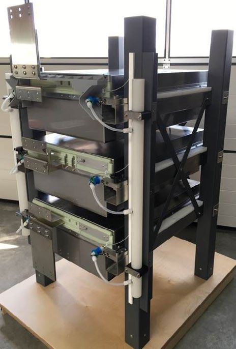
Insights Issue October 2018
Best Paper Award // Highly Integrated Two-Phase
SiC Boost Converter with 3D-Printed Fluid Coolers
and 3D-Printed Inductor Bobbins
With the use of Selective Laser Melting (SLM), new circuits for each phase and galvanically isolated volt- 100
3D-printed and highly compact cooling structures for age measurement circuits for the input and output V in = 200 V
power converters can be realized. The highly inte- voltages are integrated. 99
V in = 400 V
grated two-phase full-SiC boost converter presented The 3D-printed transistor cooler allows space-efficient
Efficiency in %
features 3D-printed miniature fluid coolers as well as cooling of four power transistors in a standard TO-247 98
3D-printed inductor bobbins in order to achieve a very package and weighs only 20.2 g, which corresponds
high power density of 42.1 kW/dm3 (or 26.9 kW/kg, to 2.7 % of the total converter weight. A picture of the 97
respectively) including control hardware while deliver- converter is shown in Fig. 1. As depicted, the wa-
ing 19.8 kW of output power. ter-cooled boost inductors, which are optimized for 96
high-frequency operation and are based on 3D-printed
» The 3D-printed transistor cooler bobbins, are located below the electronics. The induc-
95
0 5 10 15 20
tors are potted together with a 3D-printed fluid cooler Output Power in kW
allows space-efficient cooling of
to dissipate copper and core losses. The potted boost
four power transistors in a standard inductors feature a total volume of 0.28dm3, which
Fig. 1: Picture of the converter including the Fig. 2: Measured converter efficiency (fs = 400 kHz, d = 0.5)
potted inductors
TO-247 package and weighs only leads to the overall converter volume of 0.47dm3.
20.2 g.« Despite the high switching frequency of 400 kHz, the
developed DC/DC converter achieves a high efficiency
The converter is designed to boost an input voltage of of more than 97 % over almost the entire operating
400 V to an output voltage of 800 V or vice versa. The range. The measured efficiency is shown in Fig. 2 for
electronics located on three stacked PCBs occupy only a duty cycle of 50 %.
0.19 dm3 (box around the converter). This includes all
power semiconductors, gate drivers and their associ-
ated isolated supply, input and output capacitors, the Arne Hendrik Wienhausen,
3D-printed fluid cooler and all electronics necessary RWTH Aachen
for the control of the converter. Besides an FPGA and
an MCU, galvanically isolated current measurement
pcim-europe.com 6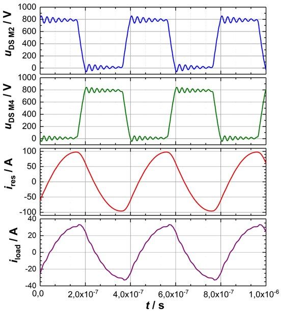
Insights Issue October 2018
Young Engineer Award // 25 kW high power resonant
inverter operating at 2.5 MHz based on SiC SMD
phase-leg modules
The use of silicon carbide (SiC) power semiconductors we were able to realize a 25 kW full-bridge inverter crossing detectors for the output voltage and resonant
allows MHz inverters to achieve higher output power prototype for driving inductive loads at 2.5 MHz as current were used. In the control unit on the FPGA,
at highest efficiency levels. Selected industrial appli- shown in Fig. 1. For the measurements, a series reso- these zero crossings were compared with the switch-
cations, e.g. high power inductively coupled plasmas, nant tank consisting of a tunable vacuum capacitor ing signals for the gates. Therefore, with this system
inductive heating or inductive charging, require it is possible to guarantee a safe operation of the
MHz inverters which can handle output powers » New possibilities with SiC generator without the need of measuring the high
above 10 kW. For the combination of fsw > 1 MHz and frequency currents and voltages in real time.
FETs in reasonable packages. «
Pout > 10 kW at η > 90 %, only soft switching full-
bridge topologies with resonant tank are reasonable.
With this topology, an efficient operation with zero and the leakage inductance of a transformer was used. Fig. 1: 25 kW inverter prototype with SMPD SiC
MOSFET phase-leg modules.
voltage switching (ZVS) can be achieved with a The measured current and voltage waveforms of the
switching frequency above the resonant frequency inverter operating with a 50 Ω high frequency load are
of the resonant tank. This allows the transistors to shown in Fig. 2. There, the inverter was running at an
be switched on with almost no switching losses. input voltage of Uin = 800 V and a switching frequency
In addition, snubber capacitors can be used in of fsw = 2.50 MHz. These parameters resulted in a res-
parallel with the MOSFETs for reducing the turn onant current of Ires = 68.9 A and an output power of
off switching losses. 25 kW. An efficiency of η = 92.53 % could be achieved
Nowadays, SiC FETs are available in several packages at this operation point. Additionally, a maximal
but these either have insufficient high frequency efficiency of 94.93 % was measured at an output power
switching characteristics, like the TO-247, or need of 14.27 kW. The lower efficiency at higher output
sophisticated cooling concepts, like the seven pin power is due to the ohmic losses in the windings of the
TO-263 (D2Pak). The combination of a good coolable transformer. Since the skin and proximity effect have a
package with good high frequency switching charac- significant influence at these frequencies, the current Fabian Denk,
teristics is possible with SiC MOSFET phase leg mod- distribution in the windings is very non-uniform. Karlsruhe Institute of Technology (KIT) Fig. 2: Measured current and voltage waveforms of
the resonant full-bridge inverter with a 50 Ω load
ules in the IXYS ISOPLUS SMPD package. By the use To ensure safe operation, a ZVS monitoring was imple-
@ Uin = 800 V, Ires = 68.9 A, fsw = 2.50 MHz and
of prototype modules, similar to the MCB30P1200LB, mented in the inverter. For this purpose analog zero Pout = 25 kW.
pcim-europe.com 7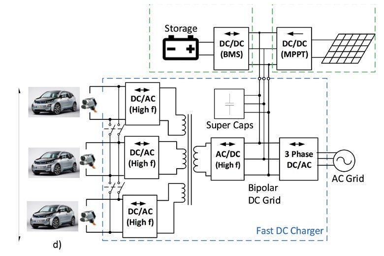
Insights Issue October 2018
Organizer Info // New e-mobility approach at the
PCIM Europe 2019
Throughout the past few years, we have repeatedly E-mobility Guided Tours. The professionally organized Fig. 1: This picture will stand for
everything e-mobility in the run-up to
reported on the increasing importance of electromobility tours are targeted towards experts in this sector and as well as during the exhibition.
as an application of power electronics. This trend take place twice a day, leading the way to exhibitors
maintains unbroken. This is surely the reason this with a distinctive focus on e-mobility, who will be
topic was well-received at the PCIM Europe from the showcasing their portfolio and answering any ques-
start, and took root so quickly. tions that may arise.
However, in order for exhibitors to be able to ade- As of now, exhibiting companies can apply for a pre-
quately present a more extensive product range in sentation slot on the tour; trade visitors will be able to
pre-register online prior to the event.
The one thing that will remain the same in 2019 is the
» NEW: Guided tours E-mobility forum. Once again on Tuesday and
to selected exhibitors « Wednesday, there will be a lecture program in collab-
oration with WEKA Fachmedien, while on Thursday,
power electronics for e-mobility, the set-up of the numerous presentations on innovations in electro
e-mobility joint stand had to be replaced with a more mobility await. Fig. 2: PCIM Europe
flexible alternative. exhibitor presenting his
products at his booth
Therefore, two changes will be made at the PCIM
Europe 2019: First, there will be »presence areas«
instead of rental stands at the E-mobility Area. Here, For further information with regard to e-mobility
exhibitors can use posters and marketing materials to at the PCIM Europe 2019, please contact
invite visitors to their main stand and learn all about Franziska Hesse at (+49) 711 61946-13 or via e-mail
their newest product innovations for electromobility. at franziska.hesse@mesago.com. She will be happy
Presence areas are available for registered exhibitors to assist you.
on request.
Second, the networking area at this location will serve
an additional purpose: As a meeting point for the new
pcim-europe.com 8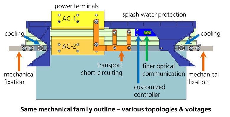
You can also read