Power Advanced N-level Digital Architecture for models of electrified vehicles and their components - PANDA
←
→
Page content transcription
If your browser does not render page correctly, please read the page content below
Proceedings of 8th Transport Research Arena TRA 2020, April 27-30, 2020, Helsinki, Finland

     Power Advanced N-level Digital Architecture for models of
             electrified vehicles and their components
 Alain BOUSCAYROLa*, Amandine LEPOUTREa, Cristi IRIMIAb, Calin HUSARb,
   Joris JAGUEMONTc, Aurélien LIEVREd, Claudia MARTISe, Dragan ZUBERf,
Volker BLANDOWc, Fei GAOh, Willem F. van DORPi, Gabriel Mihai SIRBUj, Johan
                              LECOUTEREk
                  a
                      Univ. Lille, Arts et Metiers Paris Tech, Centrale Lille, HEI, EA 2697- L2EP, F-59000 Lille, France,
                                            b
                                               Siemens Industry Software SRL, Brasov 500203, Romania
                                         c
                                           Vrije University of Brussel, Mobi-group, Brussel 1050, Belgium
                                      d
                                        Valeo Equipements Electriques Moteurs SAS, Créteil 94000, France
                                   e
                                     University of Technology of Cluj Napoca, Cluj-Napoca 400114, Romania
                                                         f
                                                           Typhoon HIL, Novi Sad 21000, Serbia
                                                     g
                                                       TUEV SUED AG, Munchen 80686, Germany
                              h
                                Université de Bourgogne Franche-Comté, FEMTO-ST, Besançon 25000, France
                                                     I
                                                       Uniresearch BV, Delft 2628XG, Netherlands
                                              j
                                                Renault Technologie Roumanie SRL, Bucarest, Romania
                                                k
                                                  Blueways International BVBA, Leuven 3001, Belgium
                                  PANDA H2020 project, Grant Agreement 824256, https://project-panda.eu/

Abstract

The PANDA project is a Research Innovation Action from the European H2020 programme. PANDA will
enable the automotive industry to speed up design and testing of innovative electrified vehicles. In the PANDA
project, multi-scale and multi-domain simulation packages are developed to interconnect all components of
electrified vehicles. The EMR (Energetic Macroscopic Representation) formalism is used to unify the model
organization. Moreover, all the models will be shared in a cloud for both stand-alone simulation and cloud
computing. On the contrary to existing solutions which are based on a structural philosophy, PANDA is focused
on functional-based approach. First results are provided to compare both approaches for the simulation of an
electric vehicle. The EMR-based functional library leads to a reduced computation time of 15% in comparison
with a structural-based simulation. This results confirms the ability of the PANDA solution for real-time
simulation in particular for Hardware-In-the-Loop testing.

Keywords: Electrified Vehicle, simulation, virtual testing, real testing, unified model organization,

 * Corresponding author. Tel.: +33-3-20-43-42-53;
   E-mail address: Alain.Bouscayrol@univ-lille.fr
Bouscayrol // TRA2020, Helsinki, Finland, April 27-30, 2020

1. Introduction

The automotive market is undergoing disruptive changes. With the growing concerns for environment, fossil
fuels depletion and global warming issue, more and more attention has been drawn on developing electrified
vehicles to reduce the use of thermal vehicles and thus Green House Gases (GHG). For example the European
Parliament adopted Regulation (EU) 2019/631 setting CO2 emission performance standards for new passenger
cars and for new light commercial vehicles in the EU for the period after 2020, European Commission (2019).
The EU policy will guide the passenger vehicle development for the next 10 years with targets in ZLEV cars
(Zero and Low Emission Vehicles). In order to achieve the targets, the car manufactures must develop a range of
hybrid and electrical vehicles adapted to the market demands. As there are many possible configurations of
hybrid and electric vehicles, flexible simulation tools are requested to speed up their developments.
The market share of electrified vehicles is thus expected to grow massively in the coming decade. While
electrified vehicles represented only 0.1% of the market in 2015, the number of electrified vehicles sale has
doubled from 2014 to 2015 (from 600 000 to 1.2 Millions), Internal Energy Agency (2016). A significant growth
of investment is thus required to comply with a mass production of electrified vehicles. In addition, significant
changes in powertrain technology are expected, Internal Energy Agency (2016).
However, the introduction of new models into the market requires development times of 3-7 years and includes
lot of risks and challenges due to high complexity of the developed products. There is a real incentive for OEMs
(Original Equipment Manufacturers) to embrace solutions that saves time and cost without sacrificing reliability
and safety. The introduction of electrified vehicles does not simplify this challenge, it rather adds to the
complexity. It is especially true at early phases of electrification, since hybrid electric vehicle (HEV) concepts
have both drivetrain solutions (combustion engine and electric drivetrain together). While Battery Electric
Vehicles (BEVs) can contribute to a further reduction of these engineering costs with simplified powertrain
concepts, the overall cost of electrified vehicles is currently higher due to expensive batteries, electric drive
components, range extender solutions, etc.
The automotive industry needs to adopt a new approach for transition from thermal vehicles to electrified
powertrains, as the development process is fundamentally different. Traditionally ICE (Internal Combustion
Engine) manufacturers develop and assemble engines and transmissions themselves based on a vertical
integration model. The situation is different in electrified powertrains. A lack of knowledge and production
capacity means that car manufacturers are relying to a larger extent on suppliers to help them build electrified
vehicles. Therefore, the automotive industry must be prepared to ensure a mass production of electrified vehicles
by using innovative methods to significantly reduce their development and testing time.
For the testing phase, Hardware-In-the-Loop (HIL) testing becomes more and more used in the automotive
industry. The first HIL tests were focused on ECU (Electronic Control Unit), whereas the Power HIL technique
aims more recently to test power components through the interconnections of these components with real-time
simulation of the other parts of the system Bouscayrol (2011). Thus, Power HIL testing has been applied to
develop various innovative vehicle components or subsystems, Allegre (2010), Kermani (2011), Barreras (2016)
Castaings (2016), Mayet (2017), Yang (2018), and Nguyen (2019). However, the quality of the HIL test depends
on the model accuracy (having in mind the real-time computation during the testing) and new dedicated ECU are
developed for fast computation of dynamical models, Abdelraham (2018). Moreover, new HIL tests are
developing using models available online, Zhang (2018), which enables sharing experience from different parts
of the world. All these developments are not yet achieved in structured way. Furthermore, most of the time
simplified (static) models are used to enable a real-time computation, but with lower accuracy.
To develop virtual testing and real testing, a first approach would be to propose interconnection of existing
simulation tools, as developed as in many H2020 European projects, Ponchant (2017), Santaroni (2018). This
method requires the development of adapted interfaces to propose seamless integration. However, these
supplementary interfaces lead to an increase of the global computation time that is not relevant for real-time
simulation or testing.
In the PANDA project, PANDA 2019, an interconnection methodology for model organisation toward standards
will be developed. A common framework will be applied in different software packages without adaptation
interface. It will solve the problem of incompatibility between different models of different organisations,
physical domains and levels of accuracy. PANDA intends to play a leading role in the development of software
tools and methods to improve the virtual generation of new products, new technologies and integrate virtual
development. These methods will support the complete generation of new electrified vehicles. PANDA will
provide a methodology to interconnect simulation, subsystem tests and final products. By avoiding
supplementary adaptation interfaces, PANDA is fully compatible with HIL testing. The PANDA project aims to
                                                                                                                1
Bouscayrol // TRA2020, Helsinki, Finland, April 27-30, 2020
take benefit of these recent developments and propose a more global and unified framework, which reduces the
development and testing time of power subsystems of electrified vehicles.
A typical problem of commercial software is that the outputs and the inputs of subsystems are not clearly or
systematically defined in a physical way across the entire collection of models, Chrenko (2019). Thus
unexpected problems may occur when connecting subsystems together. This approach is called structural
description where the priority is given to the physical organization of the systems (topology) that leads to user-
friendly building of the simulation. On the contrary, a functional approach focus on inputs and outputs of the
components/subsystems to respect the physical causal behaviour. This organization leads to a better system
understanding and a fast computation time, Rubin (1997), Hautier (2004). In PANDA the EMR (Energetic
Macroscopic Representation) formalism, Bouscayrol (2012), is used to organize the subsystem connexions in a
functional approach.
The PANDA philosophy is presented in this paper and the simulation of a commercial battery electric vehicle is
provided as an example. The interest in using a functional-based simulation instead of a structural-based one is
discussed in terms of computation time.
2. The PANDA project
2.1. Cloud of models
Traditionally, industrial products are developed according to the V-model (Fig. 1). On the left side in green
(development axis), the overall system specifications (e.g. driving range of an EV) are broken down into
subsystem specifications (e.g. battery capacity) and finally into component design (e.g. battery design). Once the
components are built, on the right side in orange (testing axis) everything is tested and integrated, from
component level (e.g. a physical battery) to finally a working prototype (a working EV). The advantage of the V-
process is the consistent feedback between design (left side) and validation (right side), which leads to fewer real
prototypes. However, the V-model is still a time-consuming process.
Fig. 1 The V-model of product development
PANDA will make the development process faster by adding a virtual validation axis and re-arranging the V-
model to a W-model (Fig. 2). While simulations are already used to reduce the number of physical tests, the high
accuracy needed at the system level currently requires a lot of computational effort. That makes existing
simulations too slow for real-time models. In PANDA, multi-scale and multi-domain simulation packages are
developed to interconnect all components of electrified vehicles. Thus virtual components can be as easily
connected and tested as components in real life. A cloud of models will be developed to supply both the virtual
and real testing. A unified organization is required for a seamless interconnection of these models.
2Bouscayrol // TRA2020, Helsinki, Finland, April 27-30, 2020
Time
PANDA concept Cloud of models
Level of details - 20%
system virtual prototype
specifications prototype testing
subsystem virtual subsystem
specifications subsystem testing
components components
design testing
component
realization
Fig. 2 The W-model of PANDA
2.2. Structural and functional description
The different simulation packages can be classified in two categories. In the case of a structural-based
simulation, the system is described by components connected by real links. Libraries of components are
available and the user has just to connect these components as in the real life with respect to their physical
interconnections. The advantage of structural-based descriptions is user-friendly. However, inputs/outputs (I/Os)
of the components are sometimes non compatible (conflict of association) that leads the non-respect of the
natural causality of the system and/or the use of specific algorithms to solve these conflicts, Von Bertalanfly
(1968), Iwasaki (1994). The fact that inputs and outputs do not respect the natural causality (i.e. output are
obtained after the input change) makes the system analysis difficult. Moreover the use of derivative causality or
specific solving algorithms lead to increase the computation time.
In functional-based simulation, the system is described by functions connected by virtual links (i.e. variables).
The drawback of functional-based description is that the user has to define the function and I/Os of each
component, then solve the conflict of associations before simulation. But if the functions are defined with the
respect of the natural causality, the system analysis is easier to perform, Hautier (2004). Moreover, the
computation time is minimized thanks of the use of classical solvers for OED (Ordinary Differential Equations),
Rubin (1997).
However, most of the actual simulation packages are developed based on structural description philosophy,
because of it is user-friendly and benefits of the use of fast computation solvers. As industrial companies
intensively use these types of software, there are many projects to propose co-simulation using several structural-
based software tools, Ponchant (2017), Santaroni (2018). Adapted interfaces are thus developed such as FMI
(Flexible Mock-up Interface) for an exchange variables in synchronized way. But FMIs lead to an increase of the
computation time. For these co-simulation projects, HIL testing is considered with simplified models to reduce
their computation time, e.g. static models using look-up tables, Ponchant (2017). The accuracy of the tests is
thus reduced.
2.3. PANDA organization and reference vehicles
The technical Work Packages (WPs) are organized from a methodological level to a real testing level.
- WP1 “Methods” focuses on the definition of the rules of the organization methodology and relevant
real-life scenarios for virtual and real testing of electrified vehicles.
- WP2 “E-storage” will provide multi-scale multi-domain models of batteries according to the PANDA
methodology. Moreover, a “cloud real testing” of a battery will be achieved as demonstration.
- WP3 “E-drive” will provide multi-scale multi-domain models of e-drives according to the PANDA
methodology. Moreover, a “cloud real testing” of an e-drive will be achieved as demonstration.
- WP4 “Virtual testing” will provide a simulation environment for the PANDA methodology including
cloud facilities. Reference vehicles will be simulated in Stand-Alone and Cloud virtual testing.
- WP5 “Real testing” will provide progressive real test of the different electrical subsystems of the
reference P-HEV.
3Bouscayrol // TRA2020, Helsinki, Finland, April 27-30, 2020
The flexibility of the PANDA methodology will be demonstrated on three reference vehicles to achieve the
innovations (they will be described in the final paper).
- a Battery Electric Vehicle (BEV), the Renault Zoe from Groupe Renault
- a Fuel Cell Vehicle (FCV), from the FP7 European Project MobyPOST, Faivre (2013),
- a Plug-in Hybrid Electric Vehicle (P-HEV), demon car from Valeo
The PANDA value chain (Fig. 3) is composed of 4 universities (concepts), 3 SME (innovative parts), 2 Tier-1
automotive suppliers, 1 car manufacturer and 1 certification company.
Universities SMEs Industries
method laboratory innovative subsystem industrial EV
concepts products
Standard market
develop. demos production software production
Fig. 3 The PANDA value chain
3. Common formalism and software
In order to develop the organization method and the cloud of model, PANDA will be based on a graphical
formalism for model organization. Moreover, an industrial simulation package (SimcenterAMESim) will be used
to demonstrate the applicability of the method.
3.1. Energetic Macroscopic Representation (EMR)
EMR is not a modeling tool, it is a graphical formalism to organize models and controls of multidisciplinary
systems, Bouscayrol (2012). The specific pictograms of EMR (see Appendix) describe energy sources, energy
storage, energy conversion, energy distribution and control operations. All I/Os of each component are
exclusively defined according to the physical causality (i.e. an output is an integral function of inputs i.e. an
output is delayed from inputs), Iwasaki (1994), Hautier (2004). EMR is thus a cognitive functional description
that leads to an easy understanding of the power flows within the system. In contrast to structural description,
interconnection of different subsystems should lead to difficulties in order to respect the physical causality
principle. In fact, conflicts of association should be resolve by the designer and not by the solver of the structural
software.
3.2. Simcenter AMESim
Simcenter AMESim, a well-know structural software in automotive industry, is an integrated, scalable system
simulation platform which allows engineers to virtually assess and optimize the mechatronic systems'
performance, Simcenter (2019). This commercial software package is composed of a suite of tools for modeling
and analysis of multi-domain systems comes with a set of standard and optional libraries of predefined and
validated components, covering different physical domains, all directly executable within the Simcenter
AMESim solvers.
Ready-to-use multi-physics libraries combined with application and industry-oriented solutions supported by
powerful platform capabilities let engineers rapidly create models and accurately perform analysis.
It has been selected to support the PANDA organization method and to develop the cloud of models and the
cloud computing. As most of the actual simulation packages, Simcenter AMESim is based on a structural
philosophy. The vehicle model development consists in connecting its components from available libraries.
AMESim is based on Bond-Graph, which is a structural graphical formalism, Gawthrop (2007).
4Bouscayrol // TRA2020, Helsinki, Finland, April 27-30, 2020
4. Simulation of an BEV using the EMR library of AMESim
4.1. Studied electric vehicle
The studied BEV is the ZOE from the Groupe Renault (Fig. 4). Its traction system is composed of a Li-ion
Battery of 23 kWh Ah, an electric drive of 65 kW (synchronous machine), a gearbox, a differential, two driven
wheels and a total mass of 1.47 ton.
Fig. 4 The studied Renault ZOE
4.2. EMR of the studied vehicle
The EMR of the vehicle is defined by using the modeling equations of each component. The battery and the road
are considered as energy sources (green oval). The inverter is a conversion element (orange square) as the
gearbox and the wheels. The synchronous machine is composed of an accumulation element (windings, crossed
orange rectangle) and a conversion element (orange circle). The differential distributes the energy to the wheels
(overlapped orange squares). The chassis merges the energy from both wheels (overlapped orange squares) and
store energy in its mass (crossed orange rectangle). All modeling equations can be found in Desreveaux (2020).
The control scheme (blue parallelogram) is directly obtained from the EMR thanks to a mirror effect. It leads to
define the measurements and the closed-loop controls (crossed light blue pictograms). This method has been
successfully used for simulation and HIL testing of BEV, Horrein (2017), HEV, Boulon (2013), FCV, Solano
(2011), Thermal vehicles, Horrein (2015), subways, Allègre (2010) , hybrid trains, Mayet (2013), BEV using
hybrid energy storage subsystems, Castaings (2016), Nguyen (2019), etc.
synchronous machine differential wheels
inverter gearbox Tdif1 Fwh1 chassis
ubat uvsi ism Tsm Tgear wh1 vev Ftot vev
Bat. Road
ivsi ism esm gear wh Tdif2 Fwh2 vev Fres
mvsi wh2 vev
Tdifé-ref
Fwh2-ref
uvsi-ref ism-ref Tsm-ref Tgear-ref Ftot-ref vev-ref
Tdif1-ref Fwh1-ref
Strategy
Fig. 5 EMR and inversion-based control of the Renault ZOE traction system
The model has been simulated first using Matlab-Simulink © and its EMR library, Desreveaux (2019). The
simulation has been compared with a test on a real vehicle for a real urban driving cycle (Fig. 6). The measured
velocity has been considered as input for the simulation. The error of the simulation is only of 3% on the global
energy consumption, Desreveaux (2019).
5Bouscayrol // TRA2020, Helsinki, Finland, April 27-30, 2020
Velocity (km/h)
time(s)
Fig. 6 Velocity measured during of the urban driving cycle
4.3. Simulation of the studied vehicle
An EMR library has thus been developed in AMESim for PANDA, Husar (2019). The model of the studied
BEV has been implemented in AMESim using this library (Fig. 7). A simple NEDC driving cycle is considered.
Fig. 7 EMR-based simulation of the Renault ZOE in AMESim
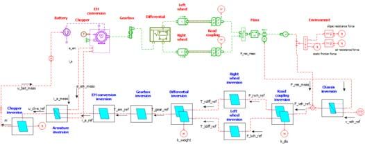
In order to define the benefit of the new EMR-based functional library, the same vehicle is also simulated using
the classical structural library of AMESim (Fig. 8). For a fair comparison, the same control scheme (deduced
from the EMR of the vehicle) is used in this structural-based simulation.
Because the same models are used in both descriptions, the simulation results are exactly the same for the
NEDC. However, the computation time of the functional-based simulation is 15% lower than the computation
time of the structural-based simulation (Fig. 9). Different fixed simulation steps have been considered using the
same computer to confirm this result. In the structural-based description, the natural causality is not always
guaranteed that leads to more computation time. This result highlights the interest of developing functional-
based library in the framework of fast simulation with applications to real-time HIL testing.
Fig. 8 Structural-based simulation of the Renault ZOE in AMESim
6Bouscayrol // TRA2020, Helsinki, Finland, April 27-30, 2020
Fig. 9 computation CPU time vs. simulation time (800 s) for different simulation steps
5. Conclusion
In the PANDA project, a functional model organization is proposed to structure the different models of
components/subsystems of electrified vehicles. This type of model organization allows I/Os of the model to be in
accordance with the causality principle. In that aim, the EMR formalism is used to organize the models to the
causality principle. A dedicated EMR-based functional library has been developed in Simcenter-AMESim,
which is a structural software. The first reference vehicle of PANDA (a commercial battery electric vehicle) has
been simulated using the classical structural library and the new functional library. The EMR-based library
allows the reduction of the computation time by 15% using the same model, the same control and the same
simulation step.
This functional approach enables thus a fast simulation computation that is compatible with real-time simulation
and HIL testing. This organization will be used for a cloud-based and stand-alone digital simulation for virtual
and real testing of innovative components. The end result will be that virtual components can be as easily
connected and tested as components in real life, enabling the automotive industry to drastically speed up the
design and testing of innovative electrified vehicles.
Acknowledgements
This project has received funding from the European Union’s Horizon 2020 research and innovation programme
under grant agreement no. 824256 (PANDA).
References
Abdelrahman A.S., Algarny K.S., Youssef M.Z., 2018. A Novel Platform for Powertrain Modeling of Electric Cars With Experimental
Validation Using Real-Time Hardware in the Loop (HIL): A Case Study of GM Second Generation Chevrolet Volt. IEEE Transactions
on Power Electronics, 33 (11), 9762-9771.
Allègre A.L., Bouscayrol A., Delarue P., Barrade P., Chattot E., El Fassi S., 2010. Energy Storage System with supercapacitor for an
innovative subway. IEEE transactions on Industrial Electronics, 57 (12) 4001-4012
Barreras J.V. , Fleischer C., Christensen A.E, Swierczynski M., Schaltz E., Andreasen S.J., Sauer D.U., 2016. An Advanced HIL Simulation
Battery Model for Battery Management System Testing. IEEE Transactions on Industry Applications, 52 (6) 5086-5099,
Boulon L., Bouscayrol A., Hissel D., Pape O., Péra M.C. 2013. Inversion-based control of a highly redundant military HEV. IEEE
transactions on Vehicular Technology, 62 (2) 500-5010.
Bouscayrol A., 2011. Hardware-In-the-Loop simulation. Industrial Electronics Handbook, second edition, tome “Control and mechatronics”,
Chapter 33, CRC Press, Taylor & Francis group, Chicago.
Bouscayrol A., Hautier J.P., Lemaire-Semail B, 2012. Graphic Formalisms for the control of multi-physical energetic systems: from COG to
EMR, in “Systemic Design Methodologies for Electrical Energy”, Chapter 3, (Ed.) ISTE Willey.
Castaings A., Lhomme W., Trigui R., Bouscayrol A., 2016. Comparison of energy management strategies of a battery/supercapacitors
system for Electric Vehicle under limitations. Applied Energy, 163, 190–200.
Chrenko D., Bouscayrol A., Lemaire-Semail B., Husar C., 2019. State-of-the-Art on vehicle simulation and testing. PANDA H2020
GA#824256, D1.1.Deliverable, public report, [Online] Available: https://project-panda.eu/ (accesses in September 2019).
Desrevaux A., Bouscayrol A., Trigui R., Castex E., Klein J., 2020. Impact of the Velocity Profile on Energy Consumption of Electric
Vehicles. IEEE transactions on Vehicular Technology, to be published in 2020, early access.
7Bouscayrol // TRA2020, Helsinki, Finland, April 27-30, 2020
European Commission, (2029). [Online] Available: https://ec.europa.eu/clima/policies/transport/vehicles/cars_en#tab-0-1 (accessed on May
2019).
Faivre S., Ravey A., Guilbert D., Ndiaye A., Gaillard A., Bouquain D., Djerdir A., Higel C., Harel F., Candusso D., 2013. Mobypost
vehicle’s powertrain design and experimental validation, FDFC Conference, Karlsruhe (Germany).
Gawthrop, P.J., Bevn G.P., 2007. Bong Graph modeling, a tutorial introduction for control engineers. IEEE Control Systems magazine,
27(2), 24-45.
Hautier J.P., Barre P.J, 2004. The causal ordering graph – A tool for modeling and control law synthesis. Studies in Informatics and Control
Journal, 13 (4), 265-283.
Horrein L., Bouscayrol A., Cheng Y., El-Fassi M., 2015. Dynamical and quasi-static multi-physical models of a diesel internal combustion
engine using Energetic Macroscopic Representation. Energy Conversion and Management, 91, 280-291
Horrein, L. Bouscayrol A., Lhomme W., Depature C., 2017. Impact of heating system on the range of an electric vehicle. IEEE transactions
on Vehicular Technology, 66 (6), 4668-4677.
Hussar C., Grovu M., Irimia C., Desreveaux A., Bouscayrol A., Ponchant M, Magnin P., Comparison of Energetic Macroscopic
Representation and structural representation on EV simulation under Simcenter AMESim. IEEE-VPPC’19, Hanoi (Vietnam), October
2019.
International Energy Agency, 2016. Global EV outlook 2016, beyond one million electric cars, IEA report.
Iwasaki I., Simon H.A. 1994. Causality and model abstraction. Artificial Intelligence, 67, 143-194.
Kermani S., Trigui R., Delprat S., Jeanneret B., Guerra T.M., 2011. PHIL Implementation of Energy Management Optimization for a Parallel
HEV on a Predefined Route. IEEE Transactions on Vehicular Technology, 60 (3), 782-792.
Mayet C., Pouget J., Bouscayrol A., Lhomme W., 2014. Influence of an energy storage system on the energy consumption of a diesel-electric
locomotive. IEEE transactions on Vehicular Technology, 63 (3), 1032-1040.
Mayet C., Delarue P., Bouscayrol A., Chatot E., 2017. Hardware-In-the-Loop Simulation of Traction Power Supply for Power Flows
Analysis of Multi-Train Subway Lines. IEEE transactions on Vehicular Technology, 66 (7), 5564-5571.
Nguyen B.H, German R., Trovao J., Bouscayrol A., 2019. Real-time energy management of battery/supercapacitor electric vehicles Based on
an adaptation of Pontryagin’s minimum principle. IEEE transactions on Vehicular Technology, 68 (1), 203-212.
PANDA 2019. PANDA H2020 European Project, GA#824256, website [Online] Available: https://project-panda.eu/ (accesses in September
2019).
Ponchant M., Barella A., Stettinger G., Benzaoui H., 2017. Standardized model integration. OBELICS H2020 GA# 769506, D3.1
Deliverable, public report, [Online] Available: https://obelics.eu/ (accessed on May 2019).
Rubin, S. Munns, J. Moskowa, 1997. The development of vehicular powertrain system modeling methodologies: philosophy and
implementation. System Automotive Engineering, paper 971089.
Santaroni L. 2018. Safety requirement and modelling guidelines. HIFI-Elements GA# 769935, D1.1 Deliverable, public report, May 2018,
[Online] Available: https://www.hifi-elements.eu/ (accessed on May 2019).
Simcenter AMESim [Online:] https://www.plm.automation.siemens.com/ (accessed on May 2019).
Solano J., Hissel D., Pera M.C. Amiet M., 2011. Practical Control Structure and Energy Management of a Testbed Hybrid Electric Vehicle.
IEEE transactions on Vehicular Technology, 60 (9), 4139-4152.
Von Bertalanffy L. 1968. General System Theory: Foundations, Development, Applications. G. Braziller Ed. New York.
Yang X, Yang C., Peng T., Chen Z., Liu B., Gui W., 2018. Hardware-in-the-Loop Fault Injection for Traction Control System. IEEE Journal
of Emerging and Selected Topics in Power Electronics, 6 (2) 696-706.
Zhang Y., Lu S., Yang Y., Guo O., 2018. Internet-Distributed Vehicle-in-the-Loop Simulation for HEVs. IEEE transactions on Vehicular
Technology, 67 (5), 3729-3739.
Appendix: EMR Pictograms
Indirect inversion
Source element Accumulation element
(closed-loop
(energy source) (energy storage)
control)
Mono-physical Mono-physical coupling Direct inversion
conversion element (open-loop
element (energy distribution) control)
Multi-physical Multi-physical coupling Coupling
conversion element inversion (energy
element (energy distribution) criteria)
8You can also read