Modelo dinámico de batería de sodio sulfuro para su aplicación en microredes
←
→
Page content transcription
If your browser does not render page correctly, please read the page content below
Antonio E. Sarasua et al.: Modelo dinámico de batería de sodio sulfuro para microredes                                5

Rev. Cienc. Tecnol.
Año 15 / Nº 20 / 2013 / 5–10

Modelo dinámico de batería de sodio sulfuro
para su aplicación en microredes
Dynamic model of sodium sulphur battery for application in microgrids
   Antonio E. Sarasua, Marcelo G. Molina, Pedro E. Mercado

Resumen

   Hoy en día, además de la tendencia a utilizar fuentes renovables de energía, existe también una tendencia a
   operar estas unidades en una forma descentralizada de modo que sean capaces, si es necesario, de trabajar
   independientemente o en forma aislada del resto del sistema de potencia. Estos sistemas se denominan microredes
   (MGs). Cuando se utilizan fuentes de energías renovables, basadas principalmente en la radiación solar o el viento,
   el problema que normalmente se enfrenta son las fluctuaciones y la naturaleza intermitente de estos recursos.
   En el caso de las MGs este problema es particularmente crítico dada la capacidad que deben tener de trabajar
   en forma aislada. Para operar con seguridad la MG normalmente se utiliza una combinación de varios tipos de
   generadores y también se hace uso de almacenamiento de energía para mantener el equilibrio de la potencia activa.
   Entre los nuevos sistemas de almacenamiento, las baterías de sodio-sulfuro (NAS) se consideran adecuadas para
   llevar a cabo diversas tareas de seguridad en las MGs. Las baterías del tipo NAS tienen son capaces de almacenar gran
   cantidad de energía y densidad de potencia por unidad de volumen y también pueden proporcionar energía tanto en
   el corto como en el largo alcance. Sin embargo, el inconveniente que estas baterías tienen es que hay pocos modelos
   que representan fielmente su comportamiento dinámico. Para un estudio adecuado de la seguridad de MGs usando
   baterías tipo NAS, es necesario identificar el comportamiento dinámico de estas baterías con un modelo preciso.
   Este artículo presenta el modelado detallado y simulación dinámica de un dispositivo de almacenamiento tipo NAS
   para su uso en microredes. También se describe el sistema de acondicionamiento de potencia (DSTATCOM) que
   se utiliza para conectar la batería NAS con la MG y la estrategia de control. Por último, el modelo de la batería NAS
   se implementa en el entorno de MATLAB / Simulink, poniéndolo a prueba en una microred.

   Palabras clave: Baterías de sodio sulfuro (NAS); Microredes; Modelación detallada; Sistemas de acondicionamiento
   de potencia; Técnicas de control.

Abstract

   Nowadays, in addition to a tendency to the use of renewable energy sources, there is also the tendency to
   operate these units in a decentralized manner so that they are able, if necessary, to work independently
   or in isolation from the rest of the power system. These systems are called microgrids (MGs). When
   using renewable energy sources, mainly based on solar radiation or wind, the problem is mainly the
   fluctuating and intermittent nature of these resources. In the case of MGs, this problem is particularly
   critical given the need of the ability to work in isolation. To operate MGs safely, a combination of several
   types of generators and also energy storage should be used to maintain the balance of active power.
   Among the new storage systems, sodium sulphur batteries (NAS) are considered suitable to perform various
   security tasks in MG. NAS batteries have a high energy and power density per unit volume and they can
   also provide energy in both the short and long range. However, the disadvantage of these batteries is that
   there are few models that genuinely represent their dynamic behavior. For a proper study of the security
   of MGs using NAS battery, it is necessary to identify their dynamic performance with an accurate model.
   This paper presents the detailed modeling and dynamic simulation of a NAS battery storage for use in MGs. It
   also describes the power conditioning system (DSTATCOM) used to connect the NAS battery with the MG and the
   control strategy. Finally, a NAS battery model was implemented in the environment of MATLAB/Simulink, and then
   tested in a microgrid system.

   Keywords: Sodium sulphur batteries (NAS); Microgrids (MG); Detailed modeling; Power conditioning system; Control
   techniques.

                                                                         Rev. Cienc. Tecnol. / Año 15 / Nº 20 / 2013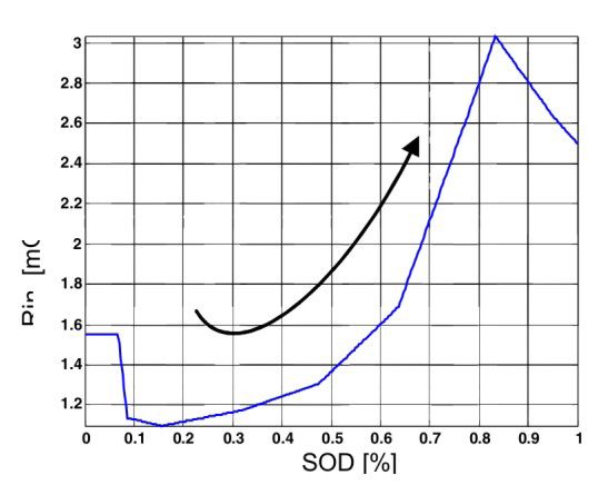
6                         Antonio E. Sarasua et al.: Modelo dinámico de batería de sodio sulfuro para microredes

Introduction                                                      Sodium-Sulphur Batteries

    At present, power utilities generate electricity using        General Description
mainly traditional non-renewable energy sources, such as
fossil (i.e. coal, oil and natural gas) and nuclear fuels, with       In April 2002, TEPCO (www.tepco.co.jp) and NGK
their associated environmental hazards. The availability          (www.ngk.co.jp) Insulators Ltd announced the commer-
and the storage form (back-up capacities) of these electric       cialization of their sodium-sulphur battery product lines
energy sources help, for instance, maintain a spinning re-        in Japan, in addition to their intent to introduce products
serve in power systems with minimum risk. Electric power          globally [2]. At present, the joint NGK-TEPCO is the most
produced by renewable energy sources (RES) distributed            important vendor of sodium-sulphur batteries for utility
around the power grid is increasingly attracting a lot of         applications, and the technology described in this paper
attention worldwide. RES-based distributed generation is          relates to NGK-TEPCO’s sodium-sulphur battery modules
considered to be important mainly to reach two goals: to          (NAS®, registered in Japan).
reduce the dependency on fossil fuels and to reduce the               A sodium-sulphur battery uses sodium and sulphur as
emission of greenhouse gases from fossil fuel combustion.         the anode and cathode respectively, while a beta-Al2O3
    From a wide range of renewable energy resources, wind         ceramic tube acts as both the electrolyte and separator
and solar energy are the focusing sources in this work. Rea-      simultaneously. This battery works on the principles of the
sons to choose them are found on their plentiful availability     electrochemical reaction between sodium and sulphur and
according to site, almost null commodity costs, and low or        the formation of sodium polysulfide.
null ecological impact. Major drawbacks, however, are the             Figure 1 illustrates the tubular design of a sodium-
unpredictability of generated power and the constrained           sulphur battery with a central sodium electrode [3-4].
back-up capacities. Unfortunately, the power generated
from sun and especially from wind has a low availability                         Beta                Molten Na
factor. The ratio between the rated generation power and                       Alumina
the effective output energy fluctuates because of climatic                      Tube
factors, such as solar radiation or wind speed variations.                                                          +
The generated power output may vary not only seasonally
or daily, but also from small variations of wind speed or
solar radiation within an hour or some minutes. Back-up
capacity constraints are referred to the impossibility to
store solar of wind energy as such. The generated electric
power output is thus not only unpredictable but also it may
arise and peak in periods when systems operators do not
                                                                                                               +
require it. Therefore, this energy is prone to be wasted or                                                   Na

discarded.
    In order to solve the unpredictability and the back-up
problems, energy storage systems may be coupled with                            Sulphur
RES-based DG and operated together as distributed energy
resources (DER) for compensating the intermittent nature          Figure 1: Schematic model of a sodium-sulphur battery.
of RES-based DG sources and thus helping improving
the short term planning. Energy storage systems used in               The open circuit voltage of the cell at 350°C is 2.075 V.
this way, enable a better management of RES-based DG              The NAS battery usually works at a temperature ranging
by means of smoothing the power output, for performing            between 300°C and 350°C, at which sodium and sulphur,
reactive compensation, load following or for increasing           as well as the reaction product polysulfide exist in liquid
spinning reserve [1]. When RES-based DG has enough                state, which supports the high reactivity of the electrodes.
storage capacity they can operate as a microgrid without a        Thermal control from a high-temp system is a built-in
connection to main power system when necessary.                   feature of the battery and it presents no specific usage or
    This work analyses the general characteristics of             safety problems [5].
sodium-sulphur batteries and their usage and effectiveness            The specific energy density of the battery reaches 760
in storage systems for MGs. Then, a sodium-sulphur bat-           Wh/kg at 350°C, nearly three times that of a lead acid
tery model is implemented and tested in the environment           battery, leading to designs of about one third the space
of MATLAB/Simulink, and then also tested in a microgrid           required for the lead acid battery for similar commercial
system.                                                           applications.

Rev. Cienc. Tecnol. / Año 15 / Nº 20 / 2013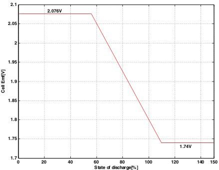
Antonio E. Sarasua et al.: Modelo dinámico de batería de sodio sulfuro para microredes 7
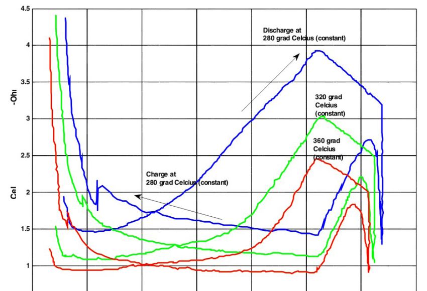
Electrical behaviour Additionally, as shown in Figure 3, depending on the
depth of discharge and temperature, the internal resistance
NAS batteries have a pulse power capability of over of the cell can varies four times (from 1 to 4 mΩ).
five times the continuous rating (for 30 seconds). This
pulse-power capability is also available even if the unit
is currently in the middle of a long term discharge for
peak saving (PS). This attribute enables the battery to be
economically used in combined power quality (PQ) and
PS applications [2]. They are competitive in combined
function applications of a few seconds or several hours.
The ability to inject power for short periods is useful to
mitigate voltage sags or momentary outages and sufficient
amount to address the majority of PQ events and to support
a transition to a backup generator [6].
Through adequate cells arrangements (series or parallel
arrays) the battery modules can then be optimized for PQ
or PS service in different values [7]. Typical modules for Figure 3: Internal resistance variation depending on the state of
PS have 320 cells and a rated capacity of 360 kWh [8]. The charge/discharge for various temperatures in a NAS-type battery cell
(experimental from [7]).
nominal operating voltage of these modules are 700Vdc
but terminal voltage varies between 325V and 790V
hanging on state and direction of charge. Each module has Nas Battery Model
current ratings of up to 810Adc [2-5].
Either PQ and PS modules are charged to 50kW, but The development of a battery model should take into
each variant is discharged at a different rate, thereby giv- account that the internal resistance and open circuit voltage
ing a different charge/discharge ratio depending on design of a NAS battery model cannot be considered constant.
and market role. The PQ-G50 NAS battery module can In addition, the resistance must have different values
discharge at up to 250 kW for 30 seconds in addition to depending on charge direction. These especially complex
discharging at lower power levels for longer periods of features and the restrictions from NGK-TEPCO to give
time [9]. information about their product, turns difficult to obtain a
The NAS battery resistance varies with the temperature, dynamic model of a NAS battery.
i.e. the higher the module temperature, the smaller the The model tested in [7] is considered the best suited to
internal resistance becomes [7]. The effect of temperature model a NAS battery. This model takes into account the
on the internal resistance is very important as it determines non-linear battery element characteristic during charging
the limit to the battery’s peak power output. and discharging as well as the internal resistance dependen-
The battery voltage in open circuit (Voc) of NAS bat- ce and battery’s open-circuit voltage (Voc) like a function
tery depends mainly on the state of discharge (SOD). Due of SOD.
to the composition reaction, the Voc of NAS battery is To model a NAS battery module only for PQ purposes,
relatively constant but drops linearly after 60-75% SOD, the NAS battery model can be modified on the basis of
as shown in Figure 2. [7]. For short periods, the temperature can be considered
constant and the effects of charge-discharge lifecycle
resistance can be neglected. To implement a NAS battery
model in MATLAB/Simulink, the SimPowerSystems
toolbox [10] is the best suited for the proposed model, but
variable resistances cannot be modelled. The authors have
implemented a special procedure to model the variability
of the internal resistance and Voc.
Figure 4 shows a schematic of the NAS battery model
developed and implemented with SimPowerSystems
toolbox.
Figure 2: Voltage variation as a function of SOD for NAS-type battery
cell [7].
Rev. Cienc. Tecnol. / Año 15 / Nº 20 / 2013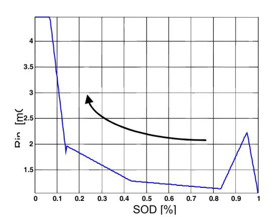
8 Antonio E. Sarasua et al.: Modelo dinámico de batería de sodio sulfuro para microredes
2.15
2.1
calculation
SOC/SOD
2.05
EMF [V]
2
1.95
1.9
1.85 x 10
-3
3
I sign?
1.8
0 0.2 0.4 0.6 0.8 1
Rint[mOhms]
SOD [%]
-
2.5
Vi =fv(SOC) 2
1.5
x 10
-3 +
0 0.2 0.4 0.6 0.8 1
Rint[mOhms]
4
SOC [%]
3.5
Discharge
3
2.5
Ri d=fd(SOC)
2
1.5
0 0.2 0.4 0.6 0.8 1
SOD [%]
Charge
Ri c=fc(SOC)
A I
Ri Figure 7: Cell electromotive force vs. SOD (Simulated)
Load
E0
Vi
Dstatcom for microgrids with nas battery
(dstatcom/nas)
A distribution static compensator or DSTATCOM is a
Figure 4: Schematic circuit of the NAS battery model implemented
fast response, solid-state power controller that provides
The NAS battery model was tested using a cell with a flexible voltage control at the point of connection to the
single resistive load to validate the model. Figures 5 and 6 utility distribution feeder for PQ improvements. If energy
shows the variation of internal resistance to change of SOD storage is included into the dc bus, the DSTATCOM can
for discharging and charging, respectively, in a cell type T5 also be used for PS improvements. A DSTATCOM with a
to 320oC. Figure 7 shows the Emf vs. SOD. battery can exchange both active and reactive power with
The NAS battery model can be easily modified to the distribution system by varying the amplitude and phase
simulate the temperature variation to work in PS mode. angle of the converter voltage with respect to the line ter-
minal voltage. The result is a controlled current flow (P or
Q) through the tie reactance between the DSTATCOM and
the distribution network in instantaneous real-time [11].
The DSTACOM/NAS system implements three modes
of operation, i.e. voltage control, power factor correction
and active power control. The integrated DSTATCOM
plus energy storage system is basically composed of the
inverter, a coupling step-up transformer, a line connection
filter, dc bus capacitors, and the array of batteries [12].
The inverter corresponds to a dc to ac switching power
inverter using Insulated Gate Bipolar Transistors (IGBT).
The output voltage control of the DSTATCOM can be
Figure 5: Internal cell resistance vs. SOD at 320 ºC for a discharge
achieved through pulse width modulation (PWM) by using
situation (Simulated) high-power fast-switched IGBTs.
The connection to the utility grid is made by using low
pass sine wave filters in order to reduce the perturbation
on the distribution system from high-frequency switching
harmonics generated by PWM control.
The multi-level control scheme for the integrated DS-
TATCOM/NAS device, consisting of an external, middle
and internal level, is based on concepts of instantaneous
power on the synchronous-rotating dq reference frame [13].
The external level control is responsible for determi-
ning the active and reactive power exchange between the
enhanced custom power device and the utility system. The
external level control scheme is designed for performing
Figure 6: Internal cell resistance vs. SOD at 320 ºC for a charge situa-
tion (Simulated) three major control objectives, that is the voltage control
Rev. Cienc. Tecnol. / Año 15 / Nº 20 / 2013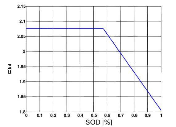
Antonio E. Sarasua et al.: Modelo dinámico de batería de sodio sulfuro para microredes                                                                              9

mode (VCM), the power factor control mode (PFCM),                                  The impact of the inclusion of a DSTATCOM/NAS
and the active power control mode (APCM) that is always                        controller at bus 3 operating in PFCM can be analyzed
activated.                                                                     from t= 3 s. At t= 3 s the DSTATCOM/NAS provides
   • The middle level control makes the expected output                        reactive power for improving the power factor and also the
   to dynamically track the reference values set by the                        voltage profile. In this way the reactive power demanded
   external level.                                                             from the electric grid at the point of common coupling
   • The internal level is responsible for generating the                      (PCC) changes from 0.5 Mvar to almost null. The active
   switching signals for the twelve valves of the three-                       power demand is also reduced due to the contribution of
   level inverter, according to the control mode (sinusoidal                   the NAS battery.
   PWM) and types of valves (IGBTs) used.                                          With the inclusion of the DSTATCOM/NAS in PFCM
                                                                               mode, the main goal of the compensator is to maintain
                                                                               a unity power factor. As can be derived from Figure 9,
NAS model tested in a microgrid                                                at t= 3 s begins the compensation of reactive power that
                                                                               rapidly provides a unity power factor independent of loads
    The MG used to validate the proposed model is depic-                       variations. In these conditions, the terminal voltage level
ted in Figure 8 as a single-line diagram. Such a system im-                    at PCC is also enhanced although at a smaller level that in
plements a 100 MVA substation represented by a Thevenin                        VCM mode.
equivalent, which feeds a distribution network operating at                        At t= 4 s, the device changes from injecting power
25 kV/50Hz. The loads are modelled by constant impedan-                        to absorbing power from the grid. In such situation, the
ces and are grouped together at bus 3. A 20 km distribution                    battery set changes from discharging to charging mode.
line modelled with parameters lumped in PI sections links                          Figure 9 presents the response of the system before,
the loads to the substation. The DSTATCOM/NAS device                           during and after the contingency described.
is connected at bus 3.                                                                                                Q Load [kvar]

                                                                                      400
    This compensator includes a 25/2.4 kV Yg/Δ step-up
                                                                                      200
transformer and a ±2 Mvar inverter coupled with a 1.5 MW
set of NAS batteries.                                                                   4
                                                                                                           Active & Reactive Power at PCC [MW]

                                                                                                               P
                                                                                        3
         Bus 1                Bus 2                 Bus 3
                                      20 km                 25 kV                       2
                                                                                                       Q

                 Z Thevenin                                                             1

                                                                    S1   S2                                        Power Factor at PCC
 Substation                   25/2.4 kV                                                 1

   25 kV                        Yg/Δ
 100 MVA                                                                              0.99

                                                              2 MW 0.25 Mvar
                      DSTATCOM/                                                                                     Bus 3 Voltage [pu]
                                                            0.25 Mvar                   1
                         BESS
                     2 Mvar/1.5 MW
                                                                                      0.95
                                           NAS
                                          Battery
                                                                                       0.9
                                                                                             0     1       2                3            4       5   Time [s]   6

Figure 8: Single-line diagram of the microgrid test system with DSTA-
COM/NAS system                                                                 Figure: Simulation of the DSTATCOM/NAS system in a micro grid.

    Performance of the models and control schemes is
analyzed by computer simulation performed in SimPower-                         Conclusion
Systems of SIMULINK/MATLAB™ [10]. A variable load
is connected at bus 3 and is changed during the simulation                        The sodium–sulphur battery presents interesting oppor-
in order to verify the dynamic response of the proposed                        tunities for energy storage in power systems. The sodium-
compensator/battery system.                                                    sulphur batteries are much smaller and lighter than other
    The topology presented in the test system is first tested                  classical batteries and they have neither memory effects
without the connection of the DSTATCOM/NAS device.                             nor toxic materials. Disadvantages of sodium batteries are
Under this scenario, the distribution utility feeds a group                    few when considering them for energy storage. To date, the
of 2 MW/0.5 Mvar variable loads. The supply voltages                           main obstacles for the large scale applications of sodium-
and currents are balanced and in steady state. Then at t=                      sulphur batteries are found on their high production costs
2 s, a set of loads equivalent to 0.215 Mvar are automati-                     which depend greatly on the scale of battery production.
cally connected and disconnected at t= 4 s at bus 3. The                       The most important obstacle, however, is the lack of an
inductive reactive load produces a decrease of the terminal                    electrical model that simulates its dynamic behaviour.
voltage at bus 3.                                                                 In this paper the authors have developed a new NAS

                                                                                                 Rev. Cienc. Tecnol. / Año 15 / Nº 20 / 2013
10 Antonio E. Sarasua et al.: Modelo dinámico de batería de sodio sulfuro para microredes
model suitable to study the insertion of NAS batteries 12. Molina, M. G. and Mercado, P. E.; Control
Design and Simu-
modules into microgrids systems. Dynamic system simula- lation of DSTATCOM with Energy Storage for Power
tion studies demonstrate the effectiveness of the developed Quality Improvements. 2006 IEEE PES Transmission
NAS for a single cell and in a microgrid system. More tests and Distribution Conference and Exposition Latin
and adjustments should be carried out to demonstrate its America, Venezuela. 2006.
performance in large power systems and also to check their 13. Schauder, C. D. and Mehta, M.; Vector analysis and control
long-term dynamic behaviour. of advanced static var compensators, IEE Proceedings-
C, vol. 140, no. 4, p 299-306. 1993.
References
Recibido: 19/07/2012.
(Endnotes) Aprobado: 05/04/2013.
1. Iba, K. et al; Operation And Control Of Nas Batteries On
A University Campus. 16th PSCC, Glasgow, Scotland, • Antonio E. Sarasua1.
July 14-18, 2008. Electrical Engineering from the National University of San
2. Tamyurek, B. et al; The NAS Battery: A Multi-Function Juan (UNSJ), Argentina and Ph.D. degree from the UNSJ. Dr.
Energy Storage System. Power Engineering Society Sarasua is an Associate Professor at the UNSJ. His research
General Meeting, IEEE . 4 - 1996 Vol. 4. 2003. interests include power system stability and bifurcation, simu-
3. Wen, Z. et al; Research on sodium sulphur battery for lation methods and the application of energy storage in power
energy storage. Solid State Ionics 179 p 1697–1701. systems. antonio.sarasua@gmail.com
2008.
4. Crompton, T. R.; Battery Reference Book. Newnes, Third • Marcelo G. Molina2
Edition. 2000. Electronic Engineer from the UNSJ and Ph.D. degree from
5. Nichols, B. et al; Utility -Scale Application of Sodium Sul- the UNSJ. Dr. Molina is an Associate Professor at the UNSJ
phur Battery, The Battcon 2003 Proceedings. Battcon and a Researcher of Argentinean National Council for Science
Conference, Marco Island, FL. 2003. and Technology Research (CONICET). His research interests
6. Norris, C. et al; NAS® Battery Demonstration at Ameri- include new energy technologies, simulation methods, power
can Electric Power, Sandia Report (SAND20066740). systems dynamics and control, power electronics modeling
March 2007. and design, renewable energy resources and the application
7. Hussien, Z. F. et al; Modelling of Sodium Sulphur Battery of energy storage in power systems.
for Power System Applications, Elektrika 9, NO. 2, p
66-72. 2007. • Pedro E. Mercado2
8. Bito, A.; Overview of the Sodium-Sulphur Battery for the Electromechanical Engineer from the UNSJ and Ph.D. from
IEEE Stationary Battery Committee, IEEE In Power the Aachen University of Technology, Germany. Dr. Mercado
Engineering Society General Meeting, IEEE, p 1232- currently is professor of electrical engineering at the UNSJ
1235 Vol. 2. 2005. and researcher of the CONICET. His research activities focus
9. Bito, A.; Overview of the Sodium-Sulfur (NAS) Battery on dynamic simulation, operation security, power electronics,
for the IEEE Stationary Battery Committee. Sodium- renewable energy systems and economic operation and con-
Sulfur Battery Division, NGK Insulators, Ltd. Nagoya, trol of electric power systems.
Japan. 2005.
10. SimPowerSystems User´s Guide, TransÉnergie Technolo- 1. Instituto de Energía Eléctrica–Universidad Nacional de San Juan, Av. Li-
gies Inc, 2002. bertador San Martín Oeste, 1109, 5400, San Juan, Argentina. (Sarasua@
11. Song, Y. H. and Johns, A. T.; Flexible ac transmission sys- iee.unsj.edu.ar).
tems (FACTS), 1st Ed. United Kingdom: IEE Press, p 2. CONICET/Instituto de Energía Eléctrica–Universidad Nacional de San
39-49. 1999. Juan, Av. Libertador San Martín Oeste, 1109, 5400, San Juan, Argentina.
Rev. Cienc. Tecnol. / Año 15 / Nº 20 / 2013You can also read