NIMH STATE OF CHARGE AND STATE OF HEALTH MEASUREMENT, AND THE PRIUS BATTERY SYSTEM.
←
→
Page content transcription
If your browser does not render page correctly, please read the page content below
NIMH STATE OF CHARGE AND STATE OF HEALTH
      MEASUREMENT, AND THE PRIUS BATTERY SYSTEM.

                                          Peter Leijen

                                       Literature Review

                ABSTRACT                           was invented a few years later in 1899. How-
    Nickel Metal Hydride (NiMH) cells are used     ever, at this time the high material costs of
in a variety of different applications including   Nickel based batteries limited their practical
the Toyota Prius Hybrid Electric Vehicle. NiMH     applications. The sealed Nickel Cadmium bat-
cells are an alkaline cell where the charge car-   tery as we know today only became available
rier is the hydroxide (OH − ) ion. Constant cur-   after 1947.
rent and constant voltage charge techniques            Since then battery technology has expanded
can be used to reverse the chemical reaction       at a rapid rate with batteries being used in
and restore charge to the cell. Charge termi-      nearly everything from laptop computers, cell
nation techniques based on time, voltage and       phones and even vehicles. With the rapid up-
or temperature can be used to determine when       take of battery powered products in the mar-
the cell is fully charged.                         ket it is essential that the battery management
    The state of charge measurement techniques     electronics ensure the maximum amount of ser-
described in this report are Coulomb count-        vice hours are extracted from the cells before
ing, electromotive force (EMF) method and          they are considered waste. Today’s Hybrid Elec-
impedance measurement methods. Coulomb             tric Vehicles (HEV) and Electric Vehicles (EV)
counting is the most basic method of measur-       use advanced management systems to increase
ing state of charge however it isn’t possible to   fuel economy and battery life.
determine the initial state of charge in an on-
                                                       Controlled charging, discharging and load
line situation. Impedance and EMF methods
                                                   management extend the life of battery packs
can determine the initial state of charge to an
                                                   and cells. There are three main discharge meth-
accuracy of approximately 7%, quoted by some
                                                   ods constant load, constant current and con-
literature. Coulomb counting can be used to
                                                   stant power. Equivalently there are two main
measure the capacity and health of a cell in an
                                                   charge methods, constant current and constant
off-line situation.
                                                   voltage. Each method has its advantages and
                                                   disadvantages. Effective charge and discharge
          1. INTRODUCTION
                                                   termination is essential to avoid overcharge and
Batteries have been in existence since 1859, the   over discharge. There are various different meth-
first rechargeable secondary cell was the Lead     ods to determine charge/discharge termination
Acid battery, invented in France in 1859 [3].      based on time, voltage and temperature.
The first Nickel based cell, Nickel Cadmium,          Battery State of Charge is defined to be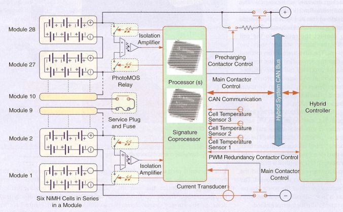
the remaining capacity in the cell. Capacity 3. NIMH CELLS AND THEIR
is a measure of the amount of energy in the CHEMISTRY
cell usually measured in Amp hours. State of
charge can be measured in a variety of differ- Nickel Metal Hydride cells or NiMH cells were
ent ways including Coulomb counting, electro- first developed in the late 1980s [2]. NiMH cells
motive force method and impedance measure- along with Nickel Cadmium or NiCad cells are
ment methods. The Toyota Prius battery man- the two major nickel based battery chemistries
agement system measures the state of charge available today. The NiMH cell has a higher
of its battery pack to determine when to start energy density but reduced cycle life compared
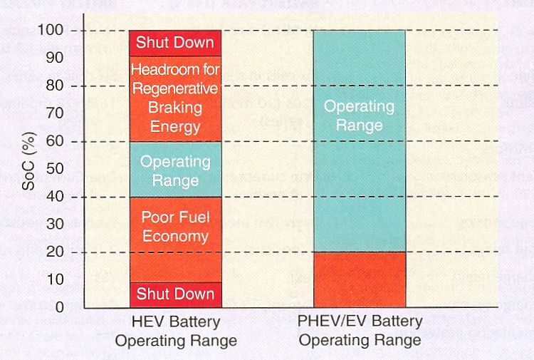
charging and stop discharging. The Prius bat- to NiCad cells [3, 8]. NiMH cells are up to 60%
tery pack is kept within 40-60% state of charge more expensive than their NiCad counterparts
during normal operating conditions. [10]. However, NiMH cells are being considered
as the drop in alternative for NiCad due to
environmental reasons [13].
2. NIMH APPLICATIONS NiCad and NiMH cells are both secondary
rechargeable cells. This means that energy can
NiMH batteries are considered to be the most be taken from the cell during discharge and re-
technically mature of the current battery tech- stored to the cell during charging. The chemi-
nologies [9, 20]. Due to their advanced nature cal reaction that occurs within a NiMH cell is
NiMH batteries can be found in a large vari- as follows [1]:
ety of applications. Applications include con- At the Positive electrode:
sumer electronics, laptops, cell phones, EVs
and HEVs just to name a few. NiMH cells are N iOOH + H2 O ←→ N i(OH)2 + OH − (1)
also used in industrial applications that require
tough batteries such as power tools, railway ap- 1
2OH − ←→ O2 + H2 O + 2e− (2)
plications and backup systems [17]. The NiMH 2
technology is replacing the Ni-Cad technology At the Negative electrode:
with possible exceptions of high drain power
1 1
tools and applications where low battery cost M Hp + OH − ←→ H2 O + M + e− (3)
p p
is the major consideration [12].
1
Prismatic NiMH cells, as opposed to cylin- O2 + H2 O + 2e− −→ 2OH − (4)
2
drical or button cells, are used in the mobile
phone and laptop industry due to their slim In these equations p is the reaction order
geometry [3]. Slim geometry prismatic cells of atomic hydrogen in the negative electrode
can be stacked tighter than similar cylindrical [1]. The cell voltage produced by the chemical
cells making them ideal for applications where potential between these two reactions is 1.2V
there is little space available. Current HEVs [10]. These two equations are depicted in figure
use prismatic cells, older HEVs use cylindrical 1 [14]:
D-size cells. NiMH batteries are widely used During charge and discharge the cell volt-
in Hybrid Electric Vehicle applications. Newer age follows a specific curve. The shape of this
HEVs (2011 onwards) are now starting to use charge or discharge curve is determined by tem-
Lithium based cells. perature, rate of charge/discharge, battery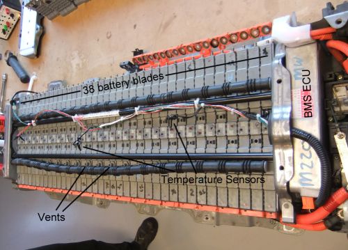
current method and the fixed voltage method.
                                                      The constant voltage method entails putting a
                                                      fixed voltage source across the cell. The con-
                                                      stant current method involves applying a fixed
                                                      current through the cell.
                                                          Discharging involves converting the chemi-
                                                      cal potential energy stored in the cell to elec-
                                                      trical energy and eventually to other forms of
                                                      energy. There are three main methods of dis-
                                                      charge constant load, constant current and con-
Figure 1: Schematic of NiMH charge and dis-           stant power. Each method has its advantages
charge [14].                                          and disadvantages. For example, a disadvan-
                                                      tage for constant power discharge is that the
health and many other factors [14]. Figure 2          current drawn peaks when battery voltage drops
shows the relationship between the discharge          [12].
curve and discharge current.

                                                      4.1. Charging Methods

                                                         4.1.1. Constant Current Charging

                                                      Constant current charging is where a constant
                                                      current is applied through the cell to reverse
                                                      the chemical reaction [6]. The problem lies in
                                                      choosing the current at which to charge. A
                                                      charging current that is low (trickle charge)
                                                      will lead to a long charge time. A current
Figure 2: Discharge curve at various discharge        that is high (fast charging) may damage the
rates [14].
                                                      cell through excessive heating etc. An alterna-
   The charge and discharge characteristics of        tive solution is to use a stepped current profile
the cell are important to consider during the         i.e. fast charge for the initial stage and trickle
charging and discharging cycle.                       charge when the cell reaches full capacity [6].
                                                           Fast or trickle charging relates to the amou-
                                                      nt of current used to charge the cell and the
      4. NIMH CHARGING AND
                                                      resulting time that it takes to charge the cell.
      DISCHARGING METHODS
                                                      Fast charging usually occurs at around 1C i.e.
The general principle behind charging a sec-          if a cell has a rated capacity of 1000 mAh then
ondary cell is to restore energy to the cell, which   a charging rate of 1C means that a constant
is converting electrical energy back to chem-         current of 1000 mA is applied to the cell un-
ical potential energy [12]. During the charg-         til it reaches the desired state of charge. The
ing process it is essential to ensure that the        literature suggests that fast charging occurs at
cell is not overcharged or that the cell reaches      max 1C to 0.5C [14].
excessive temperatures. There are two main               The curves in figure 3 compare the voltage
charging methods for batteries, the constant          and temperature characteristics of both NiMH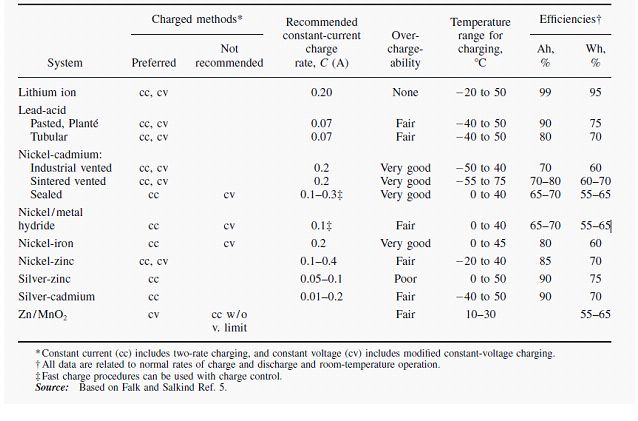
and NiCad cells under a constant current charge.     excessive current can cause gassing or other un-
For the NiCad cell the temperature remains           desired effects. Therefore a multistage or step
relatively constant during the initial phase due     charging method is recommended [3].
to the nature of the reaction. Exceeding the
oxygen recombination reaction rate causes the           4.1.3. Multistage Charging
cell temperature of the NiMH cell to rise [12,       Multistage charging or step charging is where
16]. As both cells enter the overcharged state       the charging method or parameters are changed
the cell temperature rises due to the formation      during the charging process. One example of
of oxygen on the electrodes [12].                    a multistage charging process is that used to
                                                     charge Sealed Lead Acid (SLA) batteries. The
                                                     three stages are constant current charging, con-
                                                     stant voltage charging and float charging [3].
                                                     Float charging is defined to be maintaining the
                                                     cell in a fully charged state by applying a con-
                                                     stant voltage [6].
                                                         Another example of step charging is com-
                                                     monly used to charge NiMH cells. NiMH cells
                                                     are less tolerant to overcharge therefore after
                                                     an initial fast charge (high current) the bat-
                                                     tery charger switches to a trickle charge [12].
                                                     Temperature rises (battery deterioration) can
                                                     be avoided by trickle charging at a low current,
                                                     0.033C to 0.05C for Panasonic cells [14], when
                                                     the cell approaches a fully charged state. The
                                                     table in figure 4 outlines the charging charac-
                                                     teristics of common secondary cell chemistries.

Figure 3: typical charge voltage (a) and tem-
perature (b) of NiMH (solid line) and NiCad
(broken line) [12].

   4.1.2. Constant Voltage Charging

As mentioned earlier constant voltage charging
is where a fixed voltage source, of the correct
value, is connected across the cell. In this situ-
                                                     Figure 4: Charging characteristics of secondary
ation the current is determined by the voltage
                                                     batteries [12].
difference between the source and the cell and
any parasitic series resistances in the circuit          The information in figure 4 shows that NiMH
[6]. This is a dangerous method of charging as       cells prefer constant current charging with a
there is theoretically no control on how much        recommended constant current of 0.1C. How-
current is supplied to the cell. Charging at an      ever, fast charging can be used provided the
battery charger implements some form of charge
control or charge termination.

4.2. Discharge Methods

There are three main cell discharge methods;
constant load, constant current and constant
power discharge. Simple Ohms Law shows that
under constant load discharge the current slowly
decreases as the cell voltage drops. Constant
current discharge means that the current re-
mains constant throughout the discharge cy-
cle. Constant power discharge leads to the dis-
charge current peaking when the cell voltage
drops. This information is summarised in fig-
ure 6.
    Different battery powered devices employ
different discharge methods. A simple mea-
surement of the current draw from the Toy-
ota Prius battery pack shows that it employs
neither constant load, current or power dis-
charge. The current draw from the Prius cell
depends on the users inputs. For example,
when high torque is required (heavy acceler-
ation) high current is drawn from the battery      Figure 6: Comparison between different dis-
                                                   charge methods [5].
pack. These demands place a unique charge
and discharge profile (duty cycle) on the bat-
tery pack [13].                                        The voltage curves in figure 6 (a) show how
                                                   the cell voltage varies under discharge. The
                                                   point where the voltage begins to drop rapidly
                                                   is called the end of discharge voltage, 0% SoC
                                                   [19]. Discharging a cell beyond its end of dis-
                                                   charge voltage is not recommended especially
                                                   in multi cell packs. In a multi cell pack there
                                                   will always be a cell which reaches its end of
                                                   discharge voltage first. This cell then risks
                                                   being charged in the reverse direction by the
                                                   other cells in the pack, known as cell reversal
                                                   (Figure 5) [13, 6].
                                                       Figure 7 shows the discharge characteris-
         Figure 5: Cell reversal [12].             tics of a prismatic NiMH battery. Different cell
                                                   configurations have slightly different discharge
all the charge back to the cell. This method
is ineffective because the capacity of the cell
varies with age, charge current and cycle life
(battery state of health). Timed discharge in-
volves drawing a fixed current from the cell for
a specified length of time.
The voltage drop termination method re-
lates to the curves shown in figure 3 (a). The
peak voltage and the following dip in the cell
voltage are related to the chemical changes due
to heat. For Panasonic cells this dip can range
from 5mV to 10mV per cell [14]. These volt-
age profiles are unique to individual chemistries
however some similarities exist.
The voltage plateau method terminates
charge at the top of the peak when ∆V = 0.
This method is sometimes considered safer as
it eliminates the risk of over charge [12]. Mea-
Figure 7: Discharge characteristics of a pris- surements show that the voltage plateau of the
matic NiMH battery (a) discharge at 20C (b) Toyota Prius NiMH cells occurs between 8.4
Discharge at 0.2 C rate [12].
and 8.5V.
The knee voltage relates to the sudden sharp
voltage profiles [14]. Different discharge meth-
drop in voltage as the cell approaches 100% ca-
ods suit different state of charge measurement
pacity discharged. It can be concluded from
methods.
figure 7 that the end of discharge voltage of
a prismatic NiMH cell is around the 1 to 1.1
4.3. Charge Termination
V. Panasonic quotes that the end of discharge
Charge termination is determining when the voltage, rapid charge start voltage, is closer to
cell is fully charged or discharged. Techniques 0.8 Volts per cell [19, 14].
used for charge termination can be determined The temperature related charge termina-
from the voltage and temperature characteris- tion methods relate how the chemical compo-
tics of the cell chemistry. There are six com- sition of the cell behaves during charging and
monly used methods for charge termination they what temperatures are produced. The temper-
are; timed charge, voltage drop, voltage plateau, ature cut-off method terminates charging when
temperature cut-off, delta temperature cut-off the cell reaches a specific temperature. Delta
and rate of temperature increase [12]. Timed temperature (∆T ) cut-off determines end of
discharge and knee voltage are used for dis- charge based on the rate of increase in cell
charge termination. temperature. In general a temperature termi-
The timed charge termination method is nation method is difficult to implement as sen-
the least effective. Timed charge termination sors need to be placed in inhospitable locations
involves charging the cell with a constant cur- within the cell to get accurate measurements.
rent for a period of time long enough to restore Knowing how the cell behaves during charg-ing is essential in determining when to stop
charging. Z T
SoCT = SoC0 + i dt (5)
0
5. BATTERY STATE OF CHARGE Another major disadvantage of coulomb
MEASUREMENT TECHNIQUES counting in online battery management sys-
tems is that it is not possible to predict the
Battery state of charge (SoC) is defined to be initial state of charge of the cell [19, 7]. To
the remaining capacity in the cell as a per- avoid this shortcoming and to still be able to
centage of the total capacity. There are multi- predict the state of charge of the cell it must be
ple ways of estimating battery state of charge. discharged to the cells end of discharge voltage
This review will cover some of the more com- while counting coulombs. For obvious reasons
mon methods used including Coulomb Count- this cannot be implemented in an online sys-
ing, Electromotive Force Method (EMF) and tem where the system relies on the cell having
Impedance Measurement Methods. More meth- some remaining energy, such as Hybrid Electric
ods such as chemical concentration estimation Vehicles.
methods exist however they are outside the The advantage of using coulomb counting
scope of this project [1]. Various different mod- is that it also gives an indication of the capac-
els, including the Takacs model, exist to model ity of the cell. Discharging a cell to its end
state of charge more accurately based on the of discharge voltage, while counting coulombs,
three basic SoC measurement methods described will give an indication of the cells remaining ca-
[19]. pacity. The cells capacity is obtained by fully
charging the cell (to its plateau voltage for ex-
ample) while counting coulombs.
5.1. Coulomb Counting
5.2. Electromotive Force Method
Coulomb counting is the integral over time of
the current in to and out of a cell (Eq. 5). This The electromotive force method relates the bat-
method is the easiest state of charge measure- tery open circuit voltage (OCV) to the remain-
ment method to implement in hardware, how- ing charge within the cell [7]. This relation-
ever it is cost intensive to gain accuracy [11]. ship only holds when the cell is in steady state
Due to inaccuracies in the measurement equip- condition i.e. no current is being drawn and
ment large additive errors can occur, therefore no charging is occurring. The most impor-
it is recommended to use this method alongside tant thing to note when using the electromotive
another method to account for induced errors force method is that the battery has to be idle
in dynamic situations. An example of an inac- for up to as much as 10 hours [7]. However,
curacy that can occur is the quantised nature, Windarko et al. [19] quotes that the voltage
microprocessors etc., of the measured current after 30 minutes differs by 15mV from the volt-
values. In [15] various statistical approaches to age after 600 minutes suggesting that leaving
minimise these errors are proposed. The au- the cell for 30 minutes is a suitable idle time.
thor concludes that the recursive approximate Leaving the cell at rest for a period of time al-
weighted least squares method yields the best lows the chemical reactions within the cell to
results. become complete and the internal capacitanceof the cell to discharge through internal resis-
tances (Figure 8). Article [7] only considers
self-discharge of the NiMH cell to be relevant
when the cell has been idle for more than a
week.
Figure 9: Improved Takacs model [19].
Figure 8: Battery equivalent circuit showing
internal resistances and capacitances [7].
the system (Figure 8). However, for porous
electrodes such as those in Panasonic prismatic
In [7], a piecewise linear relationship be-
cells [14] it becomes more difficult to construct
tween state of charge and EMF is quoted as a
a suitable equivalent circuit [4].
satisfactory model for the batteries they study:
The experiments conducted in [4] use a fre-
quency range from 60 mHz to 600 Hz with a
a1 EM F + b1
0-0.1 sinusoidal current of 100 mA in amplitude, at
SoC = a2 EM F + b2 0.1-0.8 (6) both open circuit conditions and under con-
a3 EM F + b3 0.8-1 stant current discharge. The cell was left to
rest for 2 hours before proceeding with the next
Article [7] also concludes that this method measurement. The results obtained boast an
can not only be used to estimate state of charge accuracy of 7% between 10% and 100% state
in an online situation but also for the steady of charge. However, impedance measurement
state case, the researcher also claims that the methods are expensive and difficult to imple-
precision of this method increases with a longer ment [7].
idle time. The Takacs model described in [19]
builds on this relationship and suggests a hys-
teresis model. The hysteresis model shown in 6. BATTERY STATE OF HEALTH
figure 9 describes the non-linearity and the dif- MEASUREMENT TECHNIQUES
ference in the relationship between OCV and
Battery state of health is defined to be the ca-
SoC in the charging state and the discharging
pacity of the cell at full charge as a percent-
state.
age of the nominal (rated) capacity of the cell
[15]. For example, if a cell is rated to be 1000
5.3. Impedance Measurement Methods
mAh and from full charge the cell only deliv-
The impedance measurement method involves ers 500 mAh then the cell is said to be at 50%
applying a small sinusoidal signal across the state of health. State of health measurement
cell and measuring the response (phase change, links the previously explained ideas of state of
attenuation etc.) to determine state of charge charge measurement and charging/discharging
[4]. This method is based largely around being techniques. If a cell is cycled i.e. discharged
able to create a suitable equivalent circuit for and charged and the state of charge/capacity ismeasured during these cycles then the charge
capacity along with the cells initial rated ca-
pacity gives the state of health, shown in figure
10.
Figure 11: Assessment and reuse process pro-
posed by Schneider et al. [16].
Figure 10: Capacity degrading with cycle life
[20].
cation stage where cell that are near 0V are
Battery state of health is also related to rejected. The remaining cells are subjected to
the impedance of the cell [3, 20]. A cell with a charge retention phase where the cell is sub-
higher AC or DC impedance is deemed to be jected to two charge discharge cycles. The cells
of lesser state of health. The DC impedance were discharged at 0.5C for 30 minutes and the
of the cell is the equivalent series resistance of voltage was recorded. Cells who’s OCV had
the cell and is measured by applying DC charge dropped under 20% of nominal were discarded
and discharge pulses to the cell and measuring [16]. This is an effective method of measuring
the voltage deflections from the open circuit cell state of health i.e. a method of measuring
voltage [3]. defect multi-cell packs.
This assumption is fine for single cell sys-
tems however the Toyota Prius (and other hy-
brid vehicles) use blades of 6 NiMH cells in se-
ries [5]. As a result blade state of health must
7. NIMH BATTERY MANAGEMENT
also take into account other failure methods
SYSTEMS (BMS)
that can occur in the individual cells. Such
failure methods can include cell reversal and
short circuited cells. Measuring these effects Battery management systems are designed to
becomes more involved. ensure that the cell undergoes no adverse treat-
Schneider et al. [16] proposes a simple met- ment i.e. overcharge or cell reversal through
hod of determining whether or not a cell is fit excessive discharge [19]. The estimation of state
for reuse. The proposed method (Figure 11) of charge of a NiMH battery is a key point for
involves a visual inspection of the cell for chem- any battery management system [7]. Precise
ical leakage at the electrodes. If a cell has ex- battery management allows the application to
cessive chemical leakage it is rejected for reuse. use the cells full operating range i.e. 100-0%
The cell is then subjected to a voltage verifi- SoC [18].7.1. Toyota Prius System vided the battery management system keeps
the pack within its prescribed operating SoC.
The Toyota Prius is a Hybrid Electric Vehicle,
Overcharge or over discharge is unavoidable on
in its simplest description a HEV has two dis-
long strings of cells (200+) and becomes more
tinct sources of power [13]. The Toyota Prius
likely as the pack ages [13].
consists of a small internal combustion engine,
two electric motor generators and a battery
pack. The battery pack consists of 38 NiMH
blades (Modules in Figure 12) which each con-
tain six NiMH cells in series [8]. The bat-
tery management system of the Prius (Figure
12) takes a differential voltage measurement
across each pair of blades, the current into the
cell is measured and three temperature mea-
surements are performed throughout the whole
pack.
Figure 13: Semi assembled battery pack.
The battery management system of HEVs
typically allow the state of charge to vary be-
tween 40-60% under normal operating condi-
tions [5, 13]. As a result the useful capacity of
the battery pack is approximately half of the
rated capacity, considering long regenerative
braking periods [13]. However, this also en-
sures that the battery pack has enough remain-
Figure 12: Typical Battery Management Sys-
tem for HEVs (i.e. 2009 Toyota Prius) [5]. ing energy to start the vehicle when parked.
The Toyota power train uses a planetary
The battery management ECU is assem- gear set as gear box providing a continuous
bled alongside the battery pack this avoids hav- range of gears. The sun gear is connected di-
ing to run high voltage sensing wires through- rectly to the internal combustion engine (ICE),
out the car. A semi assembled battery pack is the planet carrier is connected directly to mo-
shown in figure 13. Figure 13 shows the bat- tor/generator 1 (MG1) and the ring gear is
tery blades, the temperature sensors and the connected to the wheels and motor/generator
pressure vents mounted on each blade. The 2 (MG2).
same assembly also contains the high voltage The required torque based on driver inputs
relays, the rush resistor, the Hall Effect current (throttle position, vehicle speed, gear selector
transducer and the service plug. etc.) is distributed between the three compo-
Due to the Partial State of Charge oper- nents of the drive train. For example, if the
ating conditions of the Prius battery pack it driver wants to move forwards and the battery
is important that individual cells aren’t over- is fully charged (60%) a positive torque is re-
charged or over discharged [13]. This should quired at MG2 and no torque is required at the
not occur in normal operating conditions pro- ICE (dont need to charge the cell). Analysis ofa simple planetary gearbox then dictates that discharge method using voltage plateau and MG1 (the planet carrier) will also need to spin knee voltage termination methods. to keep the sun gear (ICE) stationary. If the During the discharge and charge cycle the battery is not fully charged torque transferred current and voltages will need to be logged. from both MG1 and MG2 is used to start the Performing numerical integration of the cur- ICE. If the state of charge of the battery pack is rent values i.e. Coulomb counting will give an too low (
the cell as a percentage of the rated capacity.          force method. IEEE Vehicle Power and
For single cell systems this is an accurate def-         Propulsion Conference, (3-5), 2008.
inition however for multi-cell systems, such as
the battery blades used in the Prius battery         [8] W. K. Hu, M. M. Geng, X. P. Gao, T. Bur-
pack, battery state of health also includes other        chardt, Z. X. Gong, D. Norus, and N. K.
failure methods.                                         Nakstad. Effect of long-term overcharge
                                                         and operated temperature on performance
                                                         of rechargeable nimh cells. Journal of
References                                               Power Sources, 159(2):1478–1483, 2006.

 [1] Osvaldo Barbarisi, Roberto Canaletti,           [9] U. Kohler, J. Kumpers, and M. Ull-
     Luigi Glielmo, Michele Gosso, and                   rich. High performance nickel-metal hy-
     Francesco Vasca. State of charge estima-            dride and lithium-ion batteries. Journal
     tor for nimh batteries. Proceeding of the           of Power Sources, 105(2):139–144, 2002.
     41st IEEE, 2002.
                                                    [10] Nihal Kulatatna. Power electronics design
 [2] Peter Bauerlein, Christina Antonius, Jens
                                                         handbook. Newnes, 1998.
     Lffler, and Jrg Kmpers. Progress in
     high-power nickel-metal hydride batter-        [11] Huijun     Li, Chenglin Liao, and Lifang
     ies. Journal of Power Sources, 176(2):547–          Wang.      Research on state-of-charge esti-
     554, 2008.                                          mation     of battery pack used on hybrid
                                                         electric   vehicle. IEEE, 2009. hard copy.
 [3] Isidor Buchmann. Batteries in a Portable
     World. Cadex Electronics Inc., second edi-
                                                    [12] David Linden and Thomas B Reddy.
     tion edition, 2001.
                                                         Handbook of Batteries.       McGraw-Hill,
 [4] Kenneth Bundy, Mikael Karlsson, Gran                third edition edition, 1995.
     Lindbergh, and Anton Lundqvist. An
                                                    [13] Robert F. Nelson. Power requirements for
     electrochemical impedance spectroscopy
                                                         batteries in hybrid electric vehicles. Jour-
     method for prediction of the state of
                                                         nal of Power Sources, 91(1):2–26, 2000.
     charge of a nickel-metal hydride battery at
     open circuit and during discharge. Journal
                                                    [14] Panasonic. Panasonic ideas for life Nickel
     of Power Sources, 72(2):118–125, 1998.
                                                         Metal Hydride Batteries, Technical Hand-
 [5] Jian Cao and Ali Emadi. Batteries need              book. Panasonic, 2000.
     electronics. IEEE Industrial Electronics,
                                                    [15] Gregory L. Plett. Recursive approximate
     5(1), 2011.
                                                         weighted total least squares estimation of
 [6] R.M. Dell and D.A.J. Rand. Understand-              battery cell total capacity. Journal of
     ing Batteries. The Royal Society of Chem-           Power Sources, 196(4):2319–2331, 2011.
     istry, Cambridge, 2001.
                                                    [16] E. L. Schneider, W. Kindlein Jr, S. Souza,
 [7] Wu Guoliang, Lu Rengui, Zhu Chunbo,                 and C. F. Malfatti. Assessment and reuse
     and C.C. Chan. State of charge estimation           of secondary batteries cells. Journal of
     for nimh battery based on electromotive             Power Sources, 189(2):1264–1269, 2009.
[17] Veronica Seminario. Growth opportuni-
ties for the nickel metal hydride (nimh)
batteries market, 8 Apr 2011 2011.
[18] Yanqing Shen. Adaptive online state-
of-charge determination based on neuro-
controller and neural network. Energy
Conversion and Management, 51(5):1093–
1098, 2010.
[19] N. A. Windarko, J. Choi, and Ieee.
Hysteresis Modeling for Estimation of
State-of-Charge in NiMH Battery Based
on Improved Takacs Model, pages 598–
603. International Telecommunications
Energy Conference-INTELEC. Ieee, New
York, 2009. ISI Document Delivery No.:
BPG08 Times Cited: 0 Cited Reference
Count: 11 Windarko, Novie Ayub Choi,
Jaeho Proceedings Paper 31st Interna-
tional Telecommunications Energy Con-
ference (INTELEC 09) Oct 18-22, 2009
Incheon, SOUTH KOREA 345 e 47th st,
new york, ny 10017 usa.
[20] Lu Zhang. Ac impedance studies on
sealed nickel metal hydride batteries over
cycle life in analog and digital opera-
tions. Electrochimica Acta, 43(21-22):
3333–3342, 1998.You can also read