Globally Consistent Dense Real-Time 3D Reconstruction from RGBD Data - CORE
←
→
Page content transcription
If your browser does not render page correctly, please read the page content below
Proceedings of the OAGM Workshop 2018 DOI: 10.3217/978-3-85125-603-1-25
Globally Consistent Dense Real-Time 3D Reconstruction
from RGBD Data
Rafael Weilharter1,2 , Fabian Schenk1 , Friedrich Fraundorfer1
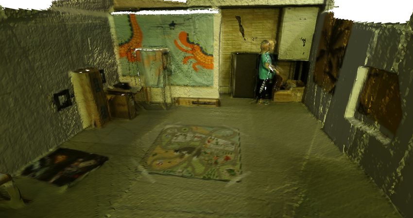
Abstract— In this work, we present a dense 3D reconstruction movement in real-time and sequentially build a dense 3D
framework for RGBD data that can handle loop closure and model [10], [7]. While such systems are real-time capable
pose updates online. Handling updates online is essential to get they accumulate significant drift over time and usually cannot
a globally consistent 3D reconstruction in real-time. We also
introduce fused depth maps for each keyframe that contain correct this drift by revisiting the same place (see Fig. 1). To
the fused depths of all associated frames to greatly increase tackle this problem, more advanced Simultaneous Localiza-
the speed for model updates. Furthermore, we show how we tion and Mapping (SLAM) systems perform loop closure and
can use integration and de-integration in a volumetric fusion pose graph optimization to reduce the drift. However, such an
system to adjust our model to online updated camera poses. approach is computationally very expensive and often only
We build our system on top of the InfiniTAM framework to
generate a model from the semi-dense, keyframe based ORB acquires a semi-dense [5] or sparse map [9]. If in addition a
SLAM2. We extensively evaluate our system on real world and dense 3D model is desired, the SLAM system usually relies
synthetic generated RGBD data regarding tracking accuracy on expensive hardware, e.g. the Bundle Fusion system [3]
and surface reconstruction. af t only runs on a combination of an NVIDIA GeForce GTX
I. INTRODUCTION Titan X and a GTX Titan Black.
In recent years, the ubiquity of inexpensive RGBD cam-
eras, pioneered by the Microsoft Kinect, has led to a series
of applications for 3D scene reconstruction in areas such
as augmented/virtual reality, robotics, gaming and general
3D model estimation. Modern 3D reconstruction systems
have to provide a globally consistent model on large scale in
Dr
real-time. This does not only require a robust camera pose
estimation algorithm but also on-the-fly model updates that
incorporate loop closures and pose refinements. The robust
camera motion estimation process is the main difference
between current systems and divides them roughly into three
categories.: (i) Iterative closest point (ICP) methods aim
to align 3D points but require sufficient 3D structure and
a correspondence matching step [7], [10]. Instead of point
clouds, (ii) direct methods estimate motion by processing
image information directly. Dense [8] and semi-dense [3],
[5] variants based on the photo-consistency assumption exist.
This makes these approaches especially susceptible to illumi-
nation changes and direct methods are typically restricted to
small inter-frame motion. (iii) Feature-based methods extract
features, match correspondences and estimate motion by
minimizing the reprojection error [4], [9]. The extracted
features are more robust to illumination changes than the Fig. 1: Reconstructed dense 3D models: No update vs our
direct methods based on the photo-consistency assumption system with keyframe based depth map fusion and global
and are also suitable for larger inter-frame motions. model update. We can see the effects especially in the upper
Regardless of the applied method, many systems rely left corners where a loop closure occurs.
solely on frame-to-model tracking to estimate the camera
*This work was financed by the KIRAS program (no 850183, CSIS- In this paper, we propose a real-time dense 3D recon-
martScan3D) under supervision of the Austrian Research Promotion Agency
(FFG).
struction method that successfully combines the state-of-
1 Institute of Computer Graphics and Vision (ICG), Graz University of the-art ORB SLAM2 system [9] with the dense volumetric
Technology, Styria, Austria fusion framework InfiniTAM [7]. To validate our method, we
2 Ludwig Boltzmann Institute for Clinical Forensic Imaging (LBI CFI),
compare the trajectory estimations and surface reconstruction
Graz, Styria, Austria
rafael.weilharter@student.tugraz.at accuracy of several methods on the standard TUM RGBD
{schenk, fraundorfer}@icg.tugraz.at benchmark dataset and the synthetic ICL NUIM dataset. The
120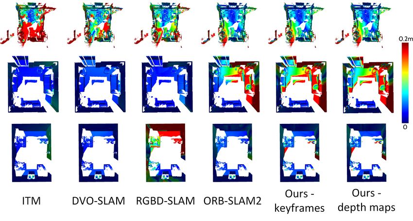
key contributions presented in this work can be summarized          order to reduce memory usage, only the scene parts inside
as:                                                                 the truncation band, i.e. the voxels close to a surface, are
   • Implementation of a de-integration method which al-            usually represented densely in an 8 × 8 × 8 block. A hash
     lows to refine and alter the 3D model online when large        table manages these voxel blocks to guarantee a constant
     changes in the estimated trajectory occur, e.g. in the case    lookup time (in case of no collisions).
     of a loop closure detection.                                      ElasticFusion [14] reconstructs the 3D world as a number
   • A global model update which can delete and merge               of circular surfels that correspond to the surfaces in the
     keyframes in retrospect.                                       real world. Managing and processing these surfels requires a
   • A keyframe based depth fusion, where we fuse in-               strong graphics card and is not capable of large-scale recon-
     formation of frames into their respective keyframes            structions. Dai et al. proposed BundleFusion [3] that models
     instead of integrating them directly into the model.           the world with a voxel block hashing framework [11]. They
     This significantly speeds up the re-integration process        always optimize over all previously seen frames, generating
     required for a global model update.                            a globally consistent model. To handle this large amount of
   • An extensive evaluation of both, the trajectory error and      data, they utilize two strong graphics cards.
     the surface reconstruction error on several benchmark             In contrast to [14], [3], we present a framework that
     data sets                                                      generates a globally consistent, dense model in real-time on
                                                                    a consumer graphics card. While pose estimation runs on
                   II. RELATED WORK                                 CPU, the 3D model is generated and processed on the GPU.
   In the past decades, 3D reconstruction has been a very           Most volumetric fusion frameworks do not allow to correct
active research field when we focus on work that utilizes           the model [7], [11], [10], e.g. after loop closure (see Fig. 1).
RGBD data. Kerl at al. [8] proposed a combination of
                                   af t                             We propose several extensions to [7] that enable on-the-fly
photometric and geometric error minimization in their vi-           corrections to generate a globally consistent model in real-
sual SLAM system. To reduce the acquired drift, they use            time.
keyframes: Every new frame is at first matched to the latest
keyframe and as long as there is not too much difference,                 III. GLOBALLY CONSISTENT DENSE 3D
i.e. the camera has not moved to far, no drift is accumulated.                     RECONSTRUCTION
Furthermore, when revisiting a previously seen region old              In this paper, we present a real-time 3D reconstruction
keyframes can enforce additional constraints on the pose            framework that works with RGBD data. We combine the
                                 Dr
graph, also known as loop closures. Although this system            accurate trajectory estimation of ORB SLAM2 [9] with the
is capable of real-time performance on a CPU, it can not do         volumetric fusion implementation from InfiniTAM v2 [7].
so at a full resolution of 640 × 480.                               We add novel techniques to InfiniTAM in order to support
   ORB SLAM 2 is a state-of-the-art feature-based SLAM              global model updates that arise from e.g. loop closure. This
system for monocular, stereo and RGBD cameras that runs             includes a de-integration method, a global model update step
in real-time on a single CPU. It estimates the camera motion        and fusion into the depth maps of keyframes to enable fast
by minimizing the reprojection error and implements loop            real-time processing.
closure, relocalization, map reuse and bundle adjustment for
pose refinement. All these methods show promising results           A. Camera Model
regarding runtime and tracking accuracy, but either generate           We receive an RGBD frame at each time step t that
no [8] or only a sparse global 3D model [9], [4].                   consists of an RGB image It and a depth map Dt . We expect
   One of the first systems to achieve a dense 3D recon-            It and Dt to be aligned and synchronized, such that at a
struction in real-time, by exploiting the massively parallel        certain pixel position ~x = (x, y)> the RGB values are given
processors on the GPU, was the KinectFusion [10]. The               as It (~x) and the corresponding depth as Dt (~x). Then the
KinectFusion system estimates the current sensor pose with          homogeneous 3D point ~X = (X,Y, Z, 1)> in the respective
an ICP algorithm and integrates the aquired data via trun-          camera coordinate system can be computed from ~x and the
cated signed distance function (TSDF). In order to achieve          corresponding depth Z = Dt (~x) with the inverse projection
real-time performance, the algorithms for both tracking and         π −1 :
mapping are fully parallelized. However, the KinectFusion                                        x−c      y − cy        >
                                                                                                      x
                                                                                π −1 (~x) = ~X =        Z,        Z, Z, 1 ,   (1)
system, which spawned several re-implementations and fur-                                          fx        fy
ther works, lacks the scalability for larger scenes due to
                                                                     where fx , fy are the focal lengths and cx , cy are the principal
memory issues (addressing and/or lack thereof).
                                                                     points. Similarly, the pixel position ~x can be recovered from
   In order to tackle the problem of a large memory footprint,      ~X as:
research on sparse volumetric representations [11], [12] has                                  X · f
                                                                                                     x        Y · fy     >
sprouted. These works successfully use either octrees or hash                   π(~X) =~x =            + cx ,        + cy .        (2)
                                                                                                  Z             Z
tables to refer to allocated memory blocks efficiently. One of
the works that is able to achieve a very high framerate while       B. Rigid Body Motion and Warping Function
reconstructing a dense 3D model is InfiniTAM [7]. It models          We restrict the motion between frames to a rigid body
the 3D world as voxel blocks using a TSDF representation. In        motion g ∈ SE(3). A common representation for g is as

                                                              121
Fig. 2: Our system takes as input the estimated poses from ORB SLAM2 and the RGBD data from the sensor. If the current
frame is not a keyframe, we update the corresponding depth map. Otherwise we fuse its depth image with the pointcloud
and update the global model. In case that a keyframe has been deleted, we de-integrate it and fuse its information into the
next best (closest) keyframe. If not, we de-integrate the frame with its old pose and re-integrate it with its new pose.


                                         af t
transformation matrix T comprising a 3 × 3 rotation matrix
R ∈ SO(3) and a 3 × 1 translation vector t:
                                                                            defined as:

                                                                                  T (~V ) = max −1, min 1,
                                                                                                           Dt (π(~V )) − Z
                                                                                                                                    !!
                                                                                                                                             ,   (6)
                           R      t                                                                               µ
                  T4×4 = 3×3 3×1 .                     (3)
                             0      1
                                                                            where ~V = (X,Y, Z)> is a voxel given by its center coordi-
The transformation of a point ~X under motion g can be                      nates, π(~V ) computes the projection of the voxel onto the
                                       Dr
written as:                                                                 depth image, while Dt (π(~V )) is the measured depth at the
                          ~ 0 = T4×4~X.
                  g(~X) = X                         (4)                     calculated image location. Since π(~V ) maps the voxel into
                                                                            the camera frame, Z is the distance between the camera and
 The rigid motion g only has 6 degrees of freedom, thus                     voxel along the optical axis. There are only values between
 T with its 12 parameters is over-parametrized. We use a                    -1 and 1 allowed, corresponding to the distances −µ and µ
 minimal representation as twist coordinates ξ defined by the               respectively (thus truncated). As a result, positive values are
 Lie algebra se(3) associated with the group SE(3). From the                assigned to voxels that reside in free space: The closer the
 6-vector ξ the transformation matrix T can be recovered by                 voxel is to the surface, the smaller its value. If the voxel lies
 the matrix exponential T = exp(ξ ).                                        directly on the surface, its value is set to zero and behind
    We define the full warping function τ that re-projects                  the surface, increasing negative values are assigned.
~x from frame j with depth D j (~x) to frame i under the                       We adapt the strategy presented by Curless and Levoy [2]
 transformation matrix Ti j as:                                             and update the TSDF for every new observation i as:
        ~x0 = τ(ξi j ,~x, D j (~x)) = π(Ti j π −1 (~x, D j (~x))).   (5)                        Wi−1 (~V )Fi−1 (~V ) + wi (~V )T (~V )
                                                                                     Fi (~V ) =                                          ,
C. Combining ORB SLAM2 and InfiniTAM                                                                    Wi−1 (~V ) + wi (~V )                    (7)
                                                                                     Wi (~V ) = Wi−1 (~V ) + wi (~V ) ,
   Fig. 2 shows the interaction between ORB SLAM2 and
InfiniTAM. Note that our contributions are depicted in green.               where W0 (~V ) = 0 and the uncertainty weight wi (~V ) is usually
We feed the RGBD data (either acquired live via sensor, or                  set to 1, which results in an averaging of the measured TSDF
from a dataset) into the ORB SLAM2 system and receive the                   observations.
estimated poses for every frame. Then we update our depth                      For a globally consistent reconstruction we need to be able
maps and adjust the global model if necessary before we                     to alter our model with updated camera poses, e.g. when a
integrate the new information into the volumetric represen-                 loop closure is detected. In order to do so, we need to delete
tation of InfiniTAM. We explain our depth map and global                    old information from the 3D model. We can de-integrate an
model updates in detail in the following sections.                          observation by reversing the operation of (7):
D. Model Updates by Re-Integration                                                              Wi−1 (~V )Fi−1 (~V ) − wi (~V )T (~V )
                                                                                     Fi (~V ) =                                          ,
 We reconstruct our scene geometry by sequentially fusing                                               Wi−1 (~V ) − wi (~V )                    (8)
RGBD data into the TSDF representation. The TSDF is                                  Wi (~V ) = Wi−1 (~V ) − wi (~V ) .

                                                                      122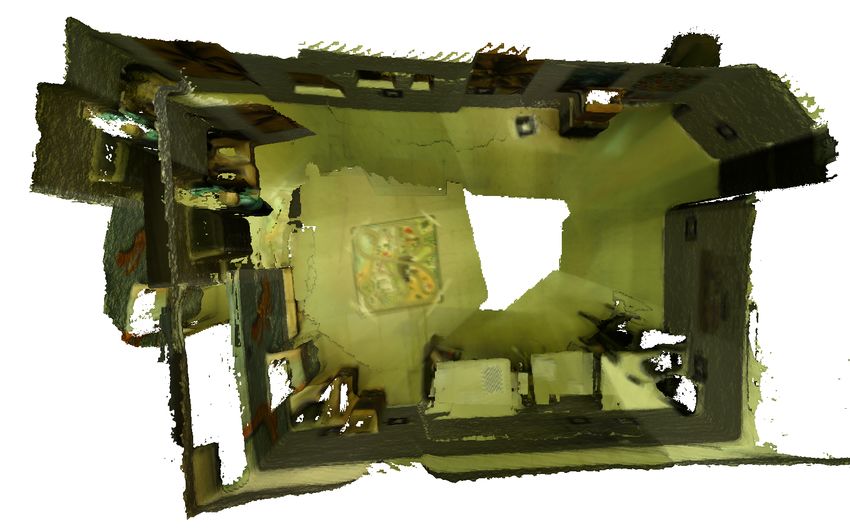
The operations of integrating and de-integrating are sym- where Θτ is a threshold. This is especially needed on edges
metric, i.e. one inverts the other. Thus, an observation, if it in the scene, where it might occur that a point far behind the
becomes invalid or updated, can be deleted by de-integrating edge in the new frame would transform onto the edge in the
it from its original pose and re-integrating it with a new pose keyframe, e.g. due to rounding. We choose to not update
if necessary. the RGB data which might yield better coloring results
but would also increase runtime. Furthermore, unlike depth
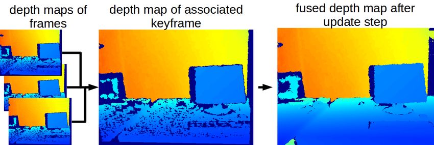
E. Depth Map Fusion in Keyframes where invalid measurements can occur, color information is
The idea behind fusing the depth maps of frames into their available for every pixel and it is therefore sufficient to color
reference keyframe is to create a system that is able to adapt the whole 3D model by just using the RGB image of the
to global changes within real-time. Without the depth map keyframe.
fusion each frame would have to be re-integrated separately Since after every new frame the 3D world model is
when a model update is induced, while our technique re- updated, we need to de-integrated the depth map with the
integrates only the fused depth maps of keyframes. Since on reference keyframe first, then update it with the new depth
average only every 10th frame is selected as keyframe, this map of the frame and finally re-integrate it. On the other
reduces the amount of operations by a factor of 10. ORB- side, if the current frame is a keyframe, we try to fuse the
SLAM2 inserts a keyframe if all of the following conditions pointclouds into the new keyframes depth map. In this case
are met: (i) more than 20 frames have passed sinice the last every homogeneous 3D point ~X˜ of the pointcloud is trans-
global relocalization, (ii) more than 20 frames have passed formed into the current keyframe by using the transformation
since the last keyframe insertion or local mapping is idle, (iii) matrix Tcn (transforming a point of frame n into the current
at least 50 keypoints are tracked in the current frame, (iv) frame c):
more than 10% of keypoints in the current frame are not seen
af t
by its reference keyframe. Additionally (for RGBD data), a ~˜ 0 = T · ~X˜ , T = T · T
X (11)
cn cn cw wn ,
keyframe is added whenever the number of close keypoints
where Tcw is the transformation matrix from world coordi-
drops below a certain threshold τt = 100 and the frame could −1 the inverse
nates into the current keyframe, and Twn = Tnw
at least create τc = 70 new close keypoints. Fig. 2 depicts
of the transformation matrix from world coordinates into the
our process flow: If a frame is not chosen as keyframe by
keyframe n. We now apply the mapping π(X 0 ) (2) to get the
ORB SLAM2, we fuse its depth map Dc into the depth map
2D image coordinates of the current keyframe the 3D point
of its reference keyframe DKF (see Fig. 3). This update step
maps to. Finally we can again calculate the update step (9)
Dr
is closely related to the volumetric fusion integration step
if the mapped point lies within the image boundaries and
presented in (7) :
satisfies (10). Every point we are able to map in this manner
Wi−1 (~x0 )DKF,i−1 (~x0 ) + wi (~x)Z 0 is removed from its pointcloud and if the number of points
DKF,i (~x0 ) = ,
Wi−1 (~x0 ) + wi (9) within a pointcloud falls below a certain threshold Θ pc we
0 0
Wi (~x ) = Wi−1 (~x ) + wi (~x) , delete the whole pointcloud. After this process, we use the
depth map as a complemented and smoothed depth image
where ~x0 = τ(ξi j ,~x, D j (~x)) is the reprojected pixel position, (see Fig. 3), which we integrate into the InfiniTAM model.
Z 0 = [TKF,c π −1 (~x, Dc~x)]z is the z-coordinate of the trans-
formed point, Dc the depth map of the current frame, TKF,c F. Global Model Update
the transformation from current frame to keyframe and the The ORB SLAM2 system continuously refines the esti-
weight wi (~x) is set equal to 1, which leads to an averaging mated poses and whenever a new keyframe is selected, we
of the depth values. Please note that we truncate ~x0 to verify the integrated poses from the model with the updated
always work on integer pixel positions. The difference to poses. If a significant change occurs, we update our 3D
the volumetric fusion (7) step is that we update the depth model in real-time. We achieve this model update by de-
map of the keyframe DKF,i instead of the TSDF values in integrating the depth map with the old pose from the model
the model. and re-integrating it with the new pose. In cases, where ORB
In order to not lose any information, we store unfused SLAM2 deletes a keyframe KFdelete , we search for the closest
points in a pointcloud. The pointcloud is represented as keyframe KFclosest and de-integrate both from the 3D model.
a vector, where each entry corresponds to a 3D point, Then we fuse KFdelete into KFclosest with (9) and re-integrate
which is transformed into the keyframe coordinates but could KFclosest into the model.
not be added to the depth map. Points are not fused into
the depth map and added to the pointcloud when either G. Implementation
of two conditions arise: (i) The point is transformed out Since this process of constant de-integrating and re-
of boundaries variables, i.e. the x and/or y coordinate are integrating can be computationally intensive, we parallelized
negative or larger than the image size or (ii) the depth the update step via CUDA specific code. Note that in a few
difference is too large, which can be described as: cases we run into the problem of collision (two or more
points in the frame correspond to the same coordinates in the
1 1 keyframe). In this case, only 1 point will be integrated and
− 0 < Θτ , (10)
~
D(x )
0 Z the other points are lost. However, this loss of information
123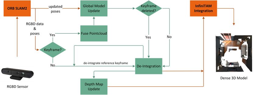
Fig. 3: Our depth map update complements and smooths the depth map of the keyframe.

can be tolerated for the sake of speed (and not needing            A. Trajectory and Drift Estimation
any atomic operations). Furthermore, we introduce a ”fast
mode”, where frames will only be integrated into the model
                                  af t                             TABLE I: ATE RMSE on the TUM RGB-D dataset and the
if a new keyframe is processed, i.e. new frames will only          synthetic ICL-NUIM dataset [m]
update the depth map of their keyframe but are not directly
integrated into the 3D model. A downside to this is that                             ITM      ICP     DVO    RGBD     ORB
visual feedback provided to the viewer is not immediate but                                  CUDA    SLAM    SLAM    SLAM2
always one keyframe behind. In this manner our system is                fr1/desk     0.291   0.144   0.169   0.027    0.022
able to process an average of 15-20 frames per second, where            fr1/desk2    0.483   0.273   0.148   0.041    0.023
the largest limiting factor is the tracking of ORB-SLAM2                fr1/room     0.523   0.484   0.219   0.104    0.069
running exclusively on the CPU.                                         fr1/xyz      0.032   0.042   0.031   0.017    0.010
                                Dr
                                                                        fr2/desk     0.114   1.575   0.125   0.092    0.079
                                                                        fr2/xyz      0.042   0.223   0.021   0.016    0.013
           IV. RESULTS AND DISCUSSION                                   fr3/office   1.258   1.161   0.120   0.034    0.011
                                                                        fr3/nstn     1.979   1.666   0.039   0.051    0.018
   To demonstrate our capabilities we test our system on                lr/kt0       0.045   0.697   0.006   0.011    0.008
several real-world image sequences from the TUM RGBD                    lr/kt1       0.009   0.045   0.005   0.013    0.162
dataset [13] and on the synthetic ICL-NUIM dataset [6].                 of/kt0       0.054   0.205   0.007   0.029    0.027
We evaluate standard InfiniTAM (ITM) [7], ICPCUDA [14],                 of/kt1       0.025   0.275   0.004   0.724    0.051
DVO SLAM [8], RGBD SLAM [4] and our method based on
ORB SLAM 2 [9]. ICPCUDA is a very fast implementation
                                                                      We use the evaluation tools provided by [13] to calculate
of ICP with online available code [1]. We run all systems in
                                                                   the absolute trajectory error (ATE) and the relative pose
their standard settings from using the code available online at
                                                                   error (RPE). As suggested in [13], we compare the root
maximum resolution of 640×480. For RGBD SLAM, we set
                                                                   mean squared error (RMSE) of the ATE and RPE. The ATE
the feature detector and descriptor type to ORB and extract a
                                                                   directly compares the absolute distances of the trajectory in
maximum of 600 keypoints per frame. In ORB SLAM2, we
                                                                   the ground truth file and the output trajectory of the various
extract 1000 features per frame with a minimum of 7 per cell
                                                                   systems. This is a good measurement for global consistency
and 8 scale pyramid levels. Finally, we run DVO SLAM with
                                                                   in SLAM systems. Let P1:n be the estimated trajectory and
its standard 3 scale pyramid levels. We test all the systems
                                                                   Q1:n the ground truth trajectory. Then we can find a least-
on an Intel Core 2 Quad CPU Q9550 desktop computer
                                                                   squares solution for the rigid-body transformation S which
with 8GB RAM and an NVIDIA GeForce GTX 480. For all
                                                                   maps P1:n onto Q1:n and compute the absolute trajectory error
models we chose a voxel size of 2cm and a truncation band
                                                                   at time step i:
µ of 8cm and limited the depth measurements from 0.2m to
                                                                                          Fi := Q−1
                                                                                                 i SPi .                     (12)
5.0m. We empirically found the parameters Θτ = 0.005 and
Θ pc = 1000. A high value choice of Θτ can result in depth         Table I shows the results for the ATE RMSE where ORB-
inconsistencies at edges (as stated in III-E), while Θτ = 0        SLAM2 outperforms all other systems on the TUM RGBD
would reject any depth map update. The purpose of Θ pc is          sequences. On the ICL-NUIM datasets, DVO-SLAM out-
to save memory by deleting the whole point cloud if it falls       shines ORB-SLAM2. This is due to the synthetic nature of
below this threshold. Therefore, a high threshold leads to a       the datasets, where perfect depth values allow a very accurate
deletion of more pointcloud entries and consequently trades        tracking for DVO-SLAM, whilst ORB-SLAM2 still needs
a loss of information for memory capacity.                         to rely on the extracted ORB features. The high error value

                                                             124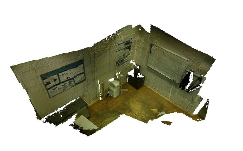
af t
Fig. 4: Surface Reconstruction: Heat maps depicting the error from the ground truth model to the estimated model. Datasets
from top to bottom: fr1/room, lr/kt1, of/kt1.
                                Dr

                                         (a) lr/kt0                                          (b) fr1/xyz

          Fig. 5: Sample reconstruction models of our approach from the TUM RGBD and ICL-NUIM datasets.

for the lr/kt1 sequence with ORB-SLAM2 is a result of not          use the TUM tools, we converted all datasets into the TUM
revisiting any structure and therefore being unable to perform     format, i.e. we changed the image and ground truth formats
a loop closure. The RPE computes the relative difference of        and added the associate files which can also be generated
the trajectory over a fixed time interval ∆. In visual odometry    with the provided tools. In cases where the algorithm is non-
systems it evaluates the drift between frames and in SLAM          deterministic, i.e. the result trajectories differ for every run,
systems it can measure the accuracy at loop closures. The          we execute the algorithm 10 times and take the mean value.
RPE at time step i is defined as:                                  Algorithms which belong to this category are ORB SLAM2
                                                                   and RGBD SLAM.
              Ei := (Q−1      −1 −1
                      i Qi+∆ ) (Pi Pi+∆ ) .               (13)
We choose to evaluate the RPE in Table II over the time            B. Surface Reconstruction Accuracy
interval of 1 second (∆ = 1s). Here again, the synthetic
ICL-NUIM datasets show slightly better results for the other          To measure the surface reconstruction accuracy, we calcu-
systems compared to ORB-SLAM2. In order to be able to              late the one-sided Hausdorff distance from the groundtruth

                                                             125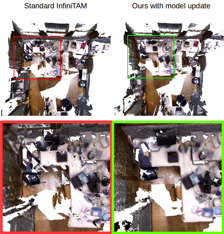
Fig. 6: Sample reconstruction models of our approach from our own Orbbec Astra Pro recordings.
TABLE II: Translational RPE RMSE on the TUM RGB-D
dataset and the synthetic ICL-NUIM dataset with ∆ = 1s [ ms ]
ITM ICP DVO RGBD ORB
af t fr1/desk
fr1/desk2
fr1/room
fr1/xyz
0.207
0.327
0.259
0.047
CUDA
0.100
0.164
0.129
0.031
SLAM
0.052
0.061
0.056
0.024
SLAM
0.036
0.045
0.053
0.027
SLAM2
0.026
0.033
0.048
0.016
fr2/desk 0.024 0.109 0.016 0.018 0.012
fr2/xyz 0.007 0.027 0.005 0.006 0.004
fr3/office 0.052 0.131 0.017 0.016 0.009
fr3/nstn 0.242 0.263 0.017 0.019 0.015
Dr
lr/kt0 0.005 0.140 0.002 0.003 0.008
lr/kt1 0.001 0.017 0.002 0.002 0.074
of/kt0 0.003 0.061 0.003 0.005 0.016
of/kt1 0.002 0.152 0.002 0.007 0.034
(a) Original InfiniTAM
TABLE III: Evaluation of the surface reconstruction accu-
racy: Hausdorff distances from the ground truth surface to
the reconstructed surfaces (m).
Ours
ITM DVO RGBD all frames keyframes depth maps
SLAM SLAM
fr1/desk 0.067 0.071 0.037 0.033 0.037 0.034
fr1/desk2 0.091 0.088 0.078 0.043 0.051 0.048
fr1/room 0.228 0.152 0.164 0.084 0.091 0.087
fr1/xyz 0.033 0.046 0.019 0.012 0.017 0.015
lr/kt0 0.004 0.005 0.006 0.008 0.016 0.016
lr/kt1 0.015 0.007 0.008 0.097 0.114 0.113
of/kt1 0.014 0.006 0.095 0.017 0.027 0.025
(b) Our approach
Fig. 7: Sample reconstruction of a room recorded and recon- 3D model to the reconstructed 3D model:
structed in real-time with our Orbbec Astra Pro. (a) shows the
dH (X,Y ) = sup inf d(x, y) , (14)
original InfiniTAM reconstruction, which is unable to adapt x∈X y∈Y
the model to loop closure (see top left corner). (b) depicts
our approach with a globally consistent model. where X is the set of groundtruth vertices, Y the set of the
reconstructed vertices and d(x, y) is the Euclidian distance
between the two vertices x and y. We sample each vertex in
X, find the distance to the closest point in Y and take the
average. Table III lists the result of this process for different
126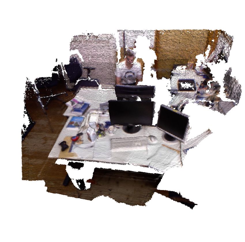
datasets and methods. ORB SLAM2 outperforms all other                      [3] A. Dai, M. Nießner, M. Zollhöfer, S. Izadi, and C. Theobalt, “Bundle-
systems on the freiburg1 datasets when integrating the model                   fusion: Real-time globally consistent 3d reconstruction using on-the-
                                                                               fly surface reintegration,” ACM Transactions on Graphics (TOG),
frame by frame without using de-integration (all frames).                      vol. 36, no. 3, p. 24, 2017.
However, note that we used already optimized trajectories                  [4] F. Endres, J. Hess, J. Sturm, D. Cremers, and W. Burgard, “3-d
for this test and thus no pose updates had to be incorporated.                 mapping with an rgb-d camera,” IEEE Transactions on Robotics,
                                                                               vol. 30, no. 1, pp. 177–187, 2014.
When we only integrate keyframes into the model, i.e. all                  [5] J. Engel, T. Schöps, and D. Cremers, “Lsd-slam: Large-scale di-
non keyframes will not be processed by the system, the                         rect monocular slam,” in European Conference on Computer Vision.
reconstruction error increases slightly. We counter this effect                Springer, 2014, pp. 834–849.
                                                                           [6] A. Handa, T. Whelan, J. McDonald, and A. Davison, “A benchmark
by using our fused depth maps. On the ICL-NUIM datasets,                       for RGB-D visual odometry, 3D reconstruction and SLAM,” in IEEE
InfiniTAM and DVO SLAM outshine ORB SLAM2. This                                International Conference on Robotics and Automation (ICRA), Hong
is due to the synthetic nature of the datasets, where perfect                  Kong, China, May 2014.
                                                                           [7] O. Kähler, V. A. Prisacariu, C. Y. Ren, X. Sun, P. Torr, and D. Murray,
depth values allow a very accurate tracking for the former                     “Very high frame rate volumetric integration of depth images on
two, whilst ORB SLAM2 still needs to rely on the extracted                     mobile devices,” IEEE Transactions on Visualization and Computer
ORB features. Furthermore, we can see in Fig. 4 that no loop                   Graphics, vol. 21, no. 11, pp. 1241–1250, 2015.
                                                                           [8] C. Kerl, J. Sturm, and D. Cremers, “Dense visual slam for rgb-
closure could be performed in the lr/kt1 dataset (due to not                   d cameras,” in International Conference on Intelligent Robots and
revisiting any structure), which leads to a larger error. Note                 Systems (IROS). IEEE, 2013, pp. 2100–2106.
that in the of/kt1 dataset our method shows some areas with                [9] R. Mur-Artal and J. D. Tardós, “Orb-slam2: An open-source slam
                                                                               system for monocular, stereo, and rgb-d cameras,” IEEE Transactions
an increased error. The reason for this is that no keyframe                    on Robotics, vol. 33, no. 5, pp. 1255–1262, 2017.
was detected there and consequently no values exist.                      [10] R. A. Newcombe, S. Izadi, O. Hilliges, D. Molyneaux, D. Kim,
   For further qualitative evaluation we tested our system on                  A. J. Davison, P. Kohi, J. Shotton, S. Hodges, and A. Fitzgibbon,
                                                                               “Kinectfusion: Real-time dense surface mapping and tracking,” in
several well known datasets (see Fig. 5) and also on datasets
                                       af t                                    10th IEEE International Symposium on Mixed and Augmented Reality
recorded with our own Orbbec Astra Pro (see Fig. 6). The                       (ISMAR). IEEE, 2011, pp. 127–136.
whole extend of our method is illustrated in Figure 7: The                [11] M. Nießner, M. Zollhöfer, S. Izadi, and M. Stamminger, “Real-time
                                                                               3d reconstruction at scale using voxel hashing,” ACM Transactions on
original InfiniTAM is unable to adapt the model to global                      Graphics (ToG), vol. 32, no. 6, p. 169, 2013.
updates and therefore structures can appear at the wrong                  [12] F. Steinbrücker, J. Sturm, and D. Cremers, “Volumetric 3d mapping
places, e.g. the reconstruction of 2 walls on the left and the                 in real-time on a cpu,” in IEEE International Conference on Robotics
                                                                               and Automation (ICRA). IEEE, 2014, pp. 2021–2028.
tables at the bottom. With our approach we obtain a globally              [13] J. Sturm, N. Engelhard, F. Endres, W. Burgard, and D. Cremers, “A
consistent model.                                                              benchmark for the evaluation of rgb-d slam systems,” in International
                                     Dr
                                                                               Conference on Intelligent Robots and Systems (IROS). IEEE, 2012,
                    V. CONCLUSIONS                                             pp. 573–580.
                                                                          [14] T. Whelan, R. F. Salas-Moreno, B. Glocker, A. J. Davison, and
   In this paper we presented a real-time capable method to                    S. Leutenegger, “Elasticfusion: Real-time dense slam and light source
combine the tracking accuracy of a state-of-the-art SLAM                       estimation,” The International Journal of Robotics Research (IJRR),
system [9] with the dense model generation of a volumetric                     vol. 35, no. 14, pp. 1697–1716, 2016.
fusion system [7]. We utilize the depth maps of all frames
but fuse them into the depth map of their corresponding
keyframes. The fused depth map is then integrated into
the 3D model instead of every single frame, resulting in a
speedup of about a factor of 10. Using fewer keyframes can
increase the speedup even further, but will also impact the
quality of the model, especially if translation and rotation
between keyframes becomes very large. In this manner our
system is able to adapt the model online, when updated poses
are available, e.g. after loop closure or bundle adjustment.
For real world data we have shown that our method yields
excelling results, especially when compared to the original
InfiniTAM ICP approach. Note that our system is not limited
to ORB SLAM2, but can in theory work with any keyframe
based tracking method. Therefore, it could enable means for
a globally consistent dense real-time 3D reconstruction for
many different SLAM and VO systems often lacking this
feature.
                           R EFERENCES
 [1] “Icpcuda,” https://github.com/mp3guy/ICPCUDA, 2018, [Accessed
     20-March-2018].
 [2] B. Curless and M. Levoy, “A volumetric method for building complex
     models from range images,” in Proceedings of the 23rd Annual
     Conference on Computer Graphics and Interactive Techniques. ACM,
     1996, pp. 303–312.

                                                                    127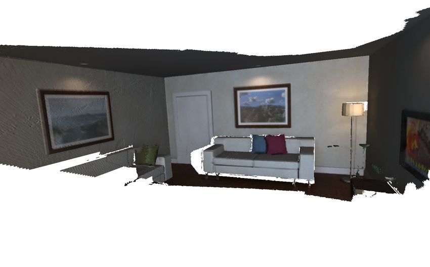
You can also read