AUTOSAR Runtime Environment and Virtual Function Bus
←
→
Page content transcription
If your browser does not render page correctly, please read the page content below
AUTOSAR Runtime Environment and Virtual
           Function Bus

                              Nico Naumann

                    nico.naumann@hpi.uni-potsdam.de

             Department for System Analysis and Modeling
           Hasso-Plattner Institute for IT-Systems Engineering
              Prof.-Dr.-Helmert-Str. 2-3, D-14482 Potsdam

  Abstract. This paper presents a selected set of concepts of the AUTo-
  motive Open System ARchitecture. Runtime Environment (RTE) and
  the Virtual Function Bus (VFB) are core parts of the AUTOSAR sys-
  tem design and facilitate relocatability of software components, one of
  the key features of AUTOSAR. The goal of this paper is to show how the
  RTE and the VFB work together in order to realizes relocatability and
  locationßtransparent interaction. A detailed view on the responsibilities
  of the Runtime Environment is shown as well as how artifacts from the
  level of the Virtual Function Bus are used for the generation of the RTE.
  Further, the concepts of runnables and the RTE mechanisms for their
  management will be shown in detail. Finally, an overview on hardware
  interaction mechanisms in the AUTOSAR architecture with respect to
  the Runtime Environment will be presented.

  Stichworte: Automotive Open System Architecture, Runtime Environ-
  ment, Virtual Function Bus, AUTOSAR, RTE, VFB, Runnables, Hard-
  ware Interaction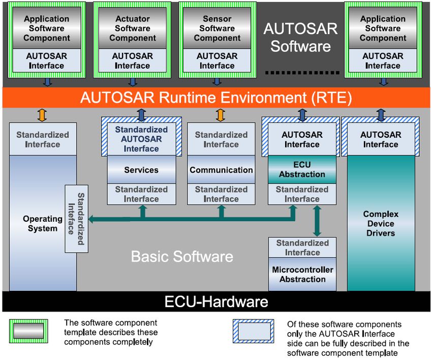
2        Nico Naumann

1      Introduction
The AUTOSAR 1 software architecture is an open standard automotive software
architecture that has been developed by a joint group of automotive vendors
and stakeholders in oder to create an integrated standard infrastructure for
vehicle software development. It aims to improve the efficiency and quality of
automotive software by means of a widely accepted standard while preserving
the competitiveness of the participants products, i.e. Cooperate on standards,
compete on implementation.
    In order to achieve a high degree of transparency against the underlying hard-
ware infrastructure, the AUTOSAR standard introduces two architectural con-
cepts that facilitate infrastructure independent software development. Namely,
these are the Virtual Function Bus (VFB) and the Runtime Infrastructure (RTE)
that are closely related to each others and that shall be introduced in detail in
the following.
    The rest of this paper is structured as follows: First, a short introduction
into the general ideas behind the concepts of RTE and VFB with respect to
the AUTOSAR mission will be given. Afterwards, a more detailed view on the
runtime environment will point out which kind of components can interact with
the RTE and what has to be provided to realize this interaction. In section 4, the
concepts of runnables will be introduced in more detail and different concepts
of mappings of tasks to artifacts of the underlying operating system will be
shown. Afterwards, in section 5, an example for the implementation of the RTE
according to the Sender-Receiver communication pattern will be given. Finally,
different mechanisms of how the RTE can interact with hardware components
will be shown in section 6.

2      Fundamentals
One of the basic principles of the AUTOSAR software design is the relocatabil-
ity of components among different architectures. In contrast to other embedded
software architectures where each component is highly specialized on the un-
derlying hardware infrastructure, OEMs and vehicle manufacturer can use the
AUTOSAR approach to redeploy existing components to any kind of hardware
infrastructure that supports the AUTOSAR standard.
    In order to realize this degree of flexibility against the underlying infrastruc-
ture, the AUTOSAR software architecture follows several abstraction principles.
In general, any piece of software within an AUTOSAR infrastructure can be seen
as an independent component while each AUTOSAR application is a set of inter-
connected AUTOSAR components. Further, the different layers of abstraction
allow the application designer to disregard several aspects of the physical system
on which the application will later be deployed on, like:

    – Type of micro controller
1
    Automotive Open System Architecture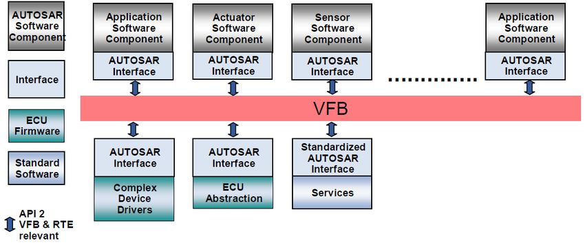
AUTOSAR Runtime Environment and Virtual Function Bus             3

Fig. 1. Overview on the principles of virtual interaction using the AUTOSAR
Virtual Function Bus

 –    Type of ECU hardware
 –    Physical location of interconnected components
 –    Networking technology / buses
 –    Instantiation of components / Number of instances

2.1     Virtual Function Bus
From a general perspective, the virtual function bus can be described as a sys-
tem modeling and communication concept. It is logical entity that facilitates the
concept of relocatability within the AUTOSAR software architecture by pro-
viding a virtual infrastructure that is independent from any actual underlying
infrastructure and provides all services required for a virtual interaction between
AUTOSAR components.
    As illustrated in figure 1, the virtual function bus is a component intercon-
nection concept that strictly separates the domain of application development
and modeling from the infrastructure. It provides generic communication ser-
vices that can be consumed by any existing AUTOSAR software component.
Although any of these services are virtual, they will then in a later develop-
ment phase be mapped to actual implemented methods, that are specific for the
underlying hardware infrastructure.

2.2     Runtime Environment
In contrast to the purely virtual specification of the communication topology
and interaction between components which is done via the virtual function bus,
the runtime environment provides an actual implementation for these artifacts.
It could also be said that the runtime environment provides an actual represen-
tation of the virtual concepts of the VFB for one specific ECU.
4 Nico Naumann
Fig. 2. Example VFB to RTE mapping where the virtual communication topol-
ogy is mapped to three different ECU’s [3]
Each ECU has its own customized RTE implementation which is generated
during the ECU Configuration process of the AUTOSAR methodology 2 . The
ECU mapping, i.e. the information about which component will deployed on
which ECU, is part of the input of this configuration process.
Depending on the location of each component, the formerly virtual inter-
action can then be mapped to real interaction implementation. More precisely,
components that are mapped onto one ECU will communicate through Intra-
ECU-Mechanisms, like function calls while Inter-ECU communication will be
realized using, e.g. a communication bus infrastructure. Since the RTE source
code is usually generated, it can be tailored by the generator to implement
exactly the communication paths required by its connected AUTOSAR com-
ponents. Thus the RTE can be seen as a static implementation of specialized
communication topologies.
Figure 2 illustrates an example transformation where the components that were
virtually connected via one single virtual function bus are mapped onto three
ECU’s. Due to the mapping on different ECU’s the different RTE’s that are
2
see [5] for more details on the ECU configuration process and the AUTOSAR
methodology in generalAUTOSAR Runtime Environment and Virtual Function Bus 5 Fig. 3. Comparison of VFB and RTE with focus on selected common concepts generated implement the communication between these components either via a local or via a remote connection. 2.3 Comparison of VFB and RTE Although the concepts of virtual function bus and the runtime infrastructure are fundamentally different, they both share a common application programming in- terface. Since at the time the application modeler defines the interaction between its application and the virtual function bus, the application programming inter- face which is used at that time has to be used by the runtime environment as well in order to provide a working environment for the modeled application. However, in other terms like system view or concepts of communication sup- ported, the VFB and the RTE have a fundamentally different conceptual base. The table in figure 3 provides an overview on various aspects that are relevant for both, Virtual Function Bus as well as Runtime Environment. 3 Responsibilities of the Runtime Environment The AUTOSAR Runtime Environment (RTE) is the central connecting element in an AUTOSAR ECU architecture. It realizes the interfaces of the Virtual Func- tion Bus in order to enable interaction between any kind of AUTOSAR software components. Since the AUTOSAR standard incorporates several types of soft- ware components, the RTE implementation has to take into account various con- straints and specialties that come with different types of software components. The following section will introduce specifics of the RTE interaction mechanisms and constraints that are introduced by the different types of software components attached to the RTE.
6         Nico Naumann

3.1     Overview
In figure 4, an architectural overview about the RTE and their respective inter-
faces to AUTOSAR components is illustrated. The interfaces that are used to
connect any type of software component, are split into three categories:

    – AUTOSAR Interface denotes software component interfaces that can be
      specified using the notation of VFB ports and communication semantics. It is
      used by Application Software Components and Sensor/Actuator components
      on the layer above the RTE as well as by the ECU abstraction and Complex
      Device Drivers on a layer below the RTE. Each component that is connected
      to the RTE via an AUTOSAR interface can provide and connect to ports
      and that way, interact with other components.
    – Standardized AUTOSAR Interfaces are using the same type of interface def-
      inition derived from the VFB as the AUTOSAR interface but are standard-
      ized in the way that the interface specification of the components attached
      via such an interface is known in advance. This kind of interface is used
      for attaching AUTOSAR services that have a predefined and standardized
      functionality.
    – Standardized Interface denotes other software component interfaces that can
      not be described using the VFB specification. Consequently, components
      attached to the RTE via a standardized interface cannot be used directly
      by other software components but are used by the RTE only. The operating
      system for instance has to provide a standardized interface to allow the RTE
      to consume services like component instantiation or task scheduling which
      must not be used by other software components.

   In the following subsection, the different types of components that can be
found in the model in figure 4 will be introduced shortly with respect to their
impact on the RTE implementation.

3.2     AUTOSAR Software Components
An AUTOSAR software component in general is the core of any AUTOSAR ap-
plication. It is built as a hierarchical composition of atomic software components
and specified using the Software Component Template. Since the RTE genera-
tion process requires a wide set of information in order to create the neccessary
methods, that information has to be provided within the Software Component
Template and serves as input for the RTE generation:
    – The Hierarchical Structure describes the composition of atomic software
      components that the AUTOSAR application software components consist
      of. This information will later be used by the RTE to create the required
      instances accordingly.
    – Ports and Interfaces describe the provided and required ports for the soft-
      ware component and their respective communication semantics which will
      have to be realized by the RTE.
AUTOSAR Runtime Environment and Virtual Function Bus 7
Fig. 4. Overview on the RTE integration into the AUTOSAR layered architec-
ture [2]
– The Internal Behavior description provides details about Runnable Entities
and RTEEvents (described in 4) that are required by the RTE for the purpose
of scheduling and method invocation.
– Specifics of the Implementation can be provided for the RTE generation
process in order to describe details about memory consumption, execution
times, etc.
3.3 AUTOSAR Services
An AUTOSAR service can be described as a
logical entity of basic software offering general functionality to be used
by AUTOSAR Software-Components. [1]
Examples for such services are Memory Services (NVRAM Manager), Network
Communication Management Services as well as Diagnostic Services and State8 Nico Naumann
Management. Services are part of the AUTOSAR basic software and can be con-
sumed by AUTOSAR Software components. They are attached to the RTE using
standardized AUTOSAR Interfaces which allows other software components to
connect to outgoing ports or provide input for incoming ports of AUTOSAR
services. Further, the semantics of ports as defined by the Virtual Function Bus
specification also apply for AUTOSAR services. In cases when an AUTOSAR
software components from the application layer request service objects, it is the
task of the runtime to map those calls to actual service object symbols on the
local ECU.
Anyhow, since AUTOSAR services provide functionality closely related to the
ECU on which they are deployed on, the RTE does not provide any mechanisms
to access a service from a remote ECU. Further a service-to-service communi-
cation is not allowed by the AUTOSAR specification since this would violate
the layered architecture. The fulfillment of these constraints has to be enforces
during the RTE generation process.
3.4 Hardware-Related Components
The AUTOSAR layered architecture specifies an ECU abstraction layer that is
supposed to decouple the software component development from the specifics of
the underlying hardware by providing a high level interface to physical values of
the actual ECU. The RTE then is responsible to provide the required commu-
nication channels between upper layer software components and the underlying
hardware to enable the ECU specific interaction. Generally, components on the
ECU abstraction layer are connected via AUTOSAR interface (see figure 4),
which provides the full flexibility of the VFB communication capabilities that
can be used for communication to and from the ECU abstraction. However,
ECU abstraction mechanisms must only be accessed by suitable Sensor/Actua-
tor software components that provide application layer interfaces to AUTOSAR
application software components. Consequently, the RTE has to ensure that no
direct access between general AUTOSAR software components and the ECU ab-
straction can occur. Further, since Sensor/Actuator components are specific for
the underlying ECU, they cannot be connected to ECU abstraction components
on remote ECU’s which has to be enforced during the RTE generation processas
well.
For more information on hardware interaction mechanisms with respect to
the runtime environment, see section 6.
4 Runnables
Since AUTOSAR software components have no direct access to the underlying
hardware or the operating system, the implementation of the atomic software
components cannot reflect artifacts like Threads or Processes. Instead, each piece
of functionality that has to be executed during runtime of the software compo-
nent is wrapped into a so-called Runnable. The VFB-Specification defines a
runnable as aAUTOSAR Runtime Environment and Virtual Function Bus 9
Sequence of instructions that can be started by the Run-Time Envi-
ronment
Each runnable that a component provides can be invoked by the RTE and is exe-
cuted within the context of the underlying operating system. An atomic software
component can consist of an arbitrary number of runnables of which each might
have its own execution semantics. During the process of ECU configuration, a
mapping between operating system tasks and existing runnables is created that
is later used by the RTE to define and perform scheduling and execution of the
runnables according to their specification.
Depending on their implementation, runnables are categorized into two dif-
ferent sets that are then mapped on different types of operating system tasks:
– Type 1 Runnables consist of a set of instructions that can be determined
to terminate within a finite time. Thus, blocking RTE calls that contain
WaitPoints cannot be contained in a type 1 runnable. Runnables that fulfill
these constraints are usually mapped to basic operating system tasks.
– Type 2 Runnables contain at least one wait point that causes the runnable to
terminate only upon the appearance of an external event (e.g. the receive of
a data value). Such runnables are mapped by the RTE to extended operating
system tasks that support the state Waiting.
The following source listing shows a pseudo-code implementation of a runnable
body. Each runnable is encapsulated into an accordingly named function body
than contains the sequence of instructions the runnable is made of. In the given
example, two statements are listed that read a value from an input port and
subsequently writes a value to an outgoing port:
void S e a t H e a t i n g_ R u n n a b l e _ r u n 1 (){
...
RTE _Rea d_InP ort_ Value (...);
// do something
R TE _ Wr it e _O u tP or t _V al u e (...);
...
}
Listing 1. Example for the body of a runnables source code (Pseudo-Code)
4.1 Integration
The concept of runnables affects several aspects of AUTOSAR, like the operat-
ing system, the runtime environment as well as the virtual function bus. Each
of them deals with runnables differently, depending on their view on the overall
system. The goal of this section is to show the dependencies and points of in-
tersection where the three participants OS, RTE and VFB are related in terms
of their integration of runnables. Figure 5 illustrates this relation and will be
explained in the following10 Nico Naumann Fig. 5. Relationship between Operating System, Runtime Environment and Vir- tual Function Bus with respect to the integration of runnables Operating System View An AUTOSAR-Compliant Operating System (e.g. OSEK OS which is referred to by the standard documents) does not know about the concepts of runnables at all. Instead, the operating system usually maintains a list of schedulable entities that are under management of a scheduling algorithm. Since runnable entities will be integrated by the runtime environment into op- erating system tasks, they will be executed anytime the corresponding OS task is scheduled. Section 4.3 will provide more details on how the mapping between operating system tasks and single runnables is performed. RTE View The runtime environment maps runnables that can be executed to- gether into one OS task. This task is then structured and controlled using RTE glue code that will control the correct execution of the runnables within the OS task. In figure 5, the boxes colored in red denote single runnables. The corre- sponding control flow that triggers the execution of such a runnable as well as the glue code (yellow box) is under control of the runtime environment. VFB View On the level of the virtual function bus (i.e. during design time of the application), the integration context of the runnable as well as the environment in which it will be executed are not of concern. Instead, anything except the sequence of single instructions within the function body and the constraints on invocation for the runnable are disregarded.
AUTOSAR Runtime Environment and Virtual Function Bus           11

4.2   RTE Events
Besides the specification of the instructions that a runnable consists of, the
RTE further requires the runnable to declare upon which type of event the
runnable is supposed to be executed. For that purpose, AUTOSAR defines a set
of RTEEvents that can either activate or resume a runnable. Table 1 provides
an overview on existing RTEEvents and their capabilities to activate or wake up
runnables.

Activation in terms of runnables and RTEEvents denotes the invocation of a
runnable instance that is mapped to an operating system task and consequently
triggers its execution when scheduled by the operating system. The invocation
itself is performed by the RTE implementation upon the appearance of the corre-
sponding RTE event that is specified by the runnable. In general, all RTEEvents
can be used to activate runnables.

Wake up Runnables of type 2 are defined to be capable of having a WaitPoint for
synchronization purposes like the confirmation of the receive of data. Such Wait-
Points are realized by blocking methods of the RTE API, e.g. RTE_Receive()
or RTE_Feedback() which in turn use RTEEvents to determine when to return
from a blocking API call. Obviously, only a subset of RTEEvent can be used
meaningfully for the wake up of runnables like for instance DataReceiveEvent.

                Event Type                     Activate Wake Up
                TimingEvent                       X
                DataReceiveEvent                  X        X
                DataReceiveErrorEvent             X
                DataSendCompleteEvent             X        X
                OperationInvokedEvent             X
                AsynchrnonousServerCallEvent      X        X
                ModeSwitchEvent                   X

Table 1. Listing of AUTOSAR RTEEvents and their capabilities to activate
and/or wake up instances of runnables

4.3   Operating System Task Mapping
As mentioned beforehand, mapping of runnables to operating system tasks is
performed during the RTE configuration process and performed on the basis
of the ECU Configuration Description. At runtime, the RTE implementation
then manages the activation and invocation of the runnables according to the
RTEEvents and semantics specified.
    The actual mapping between one or more runnables and their containing
operating system task depends heavily upon the execution semantics of the
12 Nico Naumann (a) A basic task (b) A basic task (c) An extended task con- (d) An extended containing a sin- containing mul- taining multiple category 1 task containing a gle category 1 tiple category 1 runnables single category 2 runnable runnables runnable Fig. 6. Representative scenarios for the integration of AUTOSAR runnables into operating system tasks runnables and cannot be fully exploited within this document. More precisely, since the mapping depends on information like type of the runnable (either category 1 or 2) as well as their activation and execution behavior (e.g. cyclic execution every N ms, etc.) a wide set of possible runnable configurations exists. However, in the following, several scenarios will be presented that shall give an overview on possible integration of one and more runnables within an operating system task. Figure 6 provides a graphical overview on the control flow of the scenarios described below. Scenario 1 A very common and comprehensive scenario is illustrated in figure 6(a) where a single category 1 runnable is mapped into one operating system task. A common example for such a scenario is a runnable with a time trig- gered execution (e.g. every 100ms) that provides and receives information via Sender/Receiver ports. Scenario 2 An extension of scenario 1 would be the sequential execution of several category 1 runnable that share a common cycle time (see figure 6(b). Since it is ensured that both runnables have a finite termination time (category 1 constraint) their sequential execution can be ensured to terminate timely. Consequently, a basic task that triggers the execution of both runnables in a sequence can be realized by the RTE. Scenario 3 If multiple category 1 runnables might be executed on the basis of the appearance of one or more RTEEvents, this could be realized by means of an extended task as shown in figure 6(c). Here, an extended task is running in an endless loop, continuously checking for the appearance of a new RTEEvent that is used to decide which of the two category 1 runnables need to be executed. An example for such an event might be a TimeEvent that is evaluated and according to the suitable cycle time triggers the execution of one of the runnables.
AUTOSAR Runtime Environment and Virtual Function Bus            13

Scenario 4 The integration of category 2 runnables into extended operating
system tasks is generally realized as shown in figure 6(d). Since every category
2 runnable contains one or more wait points it is not possible to determine a
finite termination time. Consequently, a sequence of category 2 runnables could
not be guaranteed to ever terminate. For that reason a category 2 runnable is
generally integrated as a standalone runnable in a single extended OS task.

5     RTE Implementation
The virtual function bus specification as introduced in [6] defines two communi-
cation patterns that can be used by an AUTOSAR software component: Sender-
Receiver and Client-Server. Both patterns have in common that, although their
usage is specified on the level of the virtual function bus, their implementation
is provided by methods of the implementation of the runtime environment.
    In order to provide a better understanding of the relations between the run-
time environment and the interaction among AUTOSAR software components,
the following section will give an in-depth introduction to the implementation
background of the runtime environment. For the sake of simplicity, this will be
done using the example of the Sender-Receiver pattern. However, the concepts
in general do apply to Client-Server as well.

5.1   Fundamentals
In the following part, a generic example will be used that is illustrated in figure
7 using the modeling notation of the AUTOSAR Virtual Function Bus specifica-
tion. It shows a simple communication architecture between one sender compo-
nent that is providing an outgoing send port which is connected to two receiving
software components. Since on the VFB level there is no statement about the
actual location of the software components, it will be shown in the following how
the generated RTE implementation might look like, depending on which kind of
deployment and configuration has been chosen.

5.2   Send/Receive Modes
Besides the distinction between the two general communication modes Send/Re-
ceive and Client/Server, ports usually come with additional information on the
read and write semantics of values on such ports. Depending on these seman-
tics, the RTE generation will later on create different implementations in order
to reflect the expected behavior that is associated with the corresponding port
semantics.
    In terms of Sender/Receiver ports, four different modes of data receive have
to be distinguished:
 – Implicit Receive denotes a semantic where the RTE provides only a copy of
   the respective value to the calling instance. That way it can be ensured that
   the value remains constant during the complete life cycle of the runnable
   and will not be changed by a remote instance.
14 Nico Naumann
Fig. 7. VFB Model for a sender-receiver communication topology
API Description
Explicit Read/Write
RTE_Read_...() Read / Write Data Value (Last-Is-Best Semantic)
RTE_Write_...()
RTE_Invalidate_...() Invalidation of previously sent value / reset to initial
RTE_Receive_...() Send or Receive Data Value
RTE_Send_...() Receive: Blocking using WaitPoint until data value is
received (DataReceiveEvent / DataReceiveErrorEvent)
Send: Non-Blocking, delegation to AUTOSAR COM
RTE_Feedback_...() Wait for completion of data send (RTE Send)
(DataSendCompleteEvent)
Implicit Read/Write
RTE_IRead_...() Implicit Reading / Writing
RTE_IWrite_...()
Table 2. Listing of AUTOSAR RTE API method prefixes for the various send
and receive communication modes
– Explicit Receive provides a non-blocking read operation on the actual vari-
able containing the latest valid value
– Wake up of wait point is used by components to request the receive of a new
value for the given variable and cause the RTE to wake up the component
if the receive operation has completed successfully.
– Activation of runnable entity is used for runnables that wish to be invoked
upon a new DataReceiveEvent and can then choose to either invoke implicit
or explicit receive operations to actually retrieve the new value.
A complete list of the interfaces provided by the runtime infrastructure for
the various communication modes can be found in table 2AUTOSAR Runtime Environment and Virtual Function Bus 15
5.3 Implementation
In the following subsection the different API calls and the generated RTE source
code that realizes these API calls will be introduced. Since the RTE generator is
not a standardized component of the AUTOSAR architecture but its implemen-
tation may vary depending on the vendor, the following source listing cannot be
understood as actual running sources but only as an illustration of the underlying
concepts. Thus, any of the following source listings are considered pseudo-code
and do not attempt to represent runnable source code of an actual programming
language.
5.3.1 API usage
Since AUTOSAR components cannot access features of the ECU communica-
tion facilities directly, the RTE provides an API that will at runtime realize
the physical communication according to the ECU configuration. However, the
syntax of the API follows a general concept that allows it to derive the names
of the corresponding API functions. The basis for each of these function names
is defined by the kind of communication mode and its corresponding API prefix
(see table 2 for examples) followed by the name of the port and the respective
value to be transmitted. That way, a receive port named PassengerDetected
that provides a single value called val could be read via the RTE API call
RTE_Read_PassengerDetected_val() for instance.
Integrated into the body of a runnable, a sender and a receiver implemen-
tation could be realized as listed in 2.
5.3.2 Sender Implementation
The details of the implementation of the RTE_Send_...() methods that are
provided to the sender component by the RTI depend on the actual ECU con-
figuration and consequently may vary. Generally, there are two kind of possible
interaction types that have to be considered by the RTE: Intra-ECU which de-
notes the communication between two software components residing on the same
ECU and Inter-ECU which denotes the situation when two software components
reside on different ECU’s that are connected via a bus network.
In the first case, since the RTE implementation is singleton instance that
connects instances of the software components, the send operation may be im-
plemented as a simple write statement to a variable in a shared memory loca-
tion. The second case instead has to realize a remote communication in order to
transmit the sent value to its destination port. For that purpose, the RTE imple-
mentation will consume a communication service object that is made available
at runtime. In the following listing this is denoted with means of a C++ macro
that is assumed to realize the according function call with the given parameters.
Both implementations can be found in listing 3
5.3.3 Receiver Implementation
Depending on the receive semantic that is used by the receive-port, the RTE im-
plementation on the receiving side of the communication channel has to provide16 Nico Naumann
implementation for the interfaces listed in table 2. In listing 4, two examples are
given that represent two possible combination of port semantics.
The first is the case of explicit reading in an intra-ECU communication ex-
ample where the caller directly reads the local variable that contains the most
recent value on the incoming port (if any). The second receive port implemen-
tation represents a Intra-ECU communication scenario that is implemented us-
ing a blocking API RTE_Receive...() that additionally implements a queue for
incoming values.
6 Hardware Interaction
As mentioned previously, an AUTOSAR software component is not allowed to
access elements of the underlying ECU hardware layer directly. Instead, the lay-
ered software architecture includes components to decouple the application logic
from the internals of hardware functionality in oder to enable relocatability. At
the level of the RTE, these components can then provide AUTOSAR Interfaces
for software components that provide normalized, hardware independent infor-
mation that abstracts from actual physical values. The ECU Abstraction layer
as well as Complex Device Drivers are such components that are accessible via
the RTE and provide access to/from the underlying hardware.
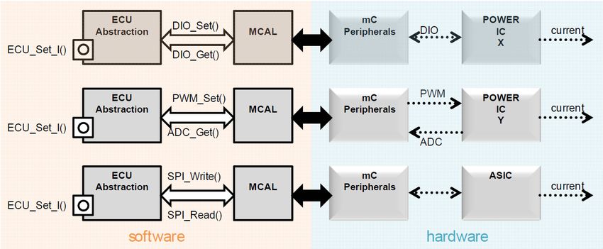
6.1 ECU Abstraction
The ECU Abstraction layer provides a unified interface for AUTOSAR software
components to access electrical values of the underlying ECU independently of
the actual ECU hardware architecture. The ECU abstraction itself is closely
coupled to the Microcontroller Abstraction (MCAL) that provides access to the
actual physical signals of the micro controller. The MCAL is a hardware spe-
cific component that is available on each standard micro controller and provides
to the basic software access to hardware information without directly accessing
the microcontrollers registers. Among other, MCAL provides access to Digi-
tal I/O, Analog/Digital Converter, FLASH, EEPROM, etc. Figure 8 illustrates
the interaction mechanisms between ECU abstraction, MCAL and the underly-
ing hardware. In the example, the ECU abstraction implements the command
ECU_Set_I() in three different ways, depending on the instruction set of the
MCAL.
6.2 Sensors and Actuators
Sensor- and Actuator-Hardware can only be accessed using the interfaces pro-
vided by the ECU abstraction. For the purpose of relocatability of AUTOSAR
software components, access to Sensor- and Actuator hardware via the ECU
abstraction is restricted to Sensor and Actuator components only. Sensor and
Actuator are atomic software components that provide an application layer in-
terface to AUTOSAR software components and implement the control over theAUTOSAR Runtime Environment and Virtual Function Bus 17
Fig. 8. Communication path from the ECU abstraction to the hardware
physical Sensor- and Actuator-Hardware. Since S/A software components are
specialized for a concrete S/A-Hardware they can only be used on an ECU that
provides the corresponding hardware.
6.3 Complex Device Drivers
Since the AUTOSAR layered software architecture restricts direct access to hard-
ware from upper layers, an additional concept is provided in order to bypass that
restriction for resource critical and/or Non-AUTOSAR compliant software com-
ponents. The Complex Device Driver provides an AUTOSAR Interface to the
application layer and has direct access to values on the physical layer. This is
usually used for the implementation of complex sensor or actuator drivers that
need direct control over the underlying hardware.
6.4 Architectural benefits
The separation of application logic from details of the underlying hardware has
several advantages compared to an integrated approach. First, the relocatability
of AUTOSAR software components can be achieved transparently since the ap-
plication source code does not concern any specifics of ECU hardware. Further,
this separation of concerns allows OEMs to develop components of each layer
independently. That way, ECU manufacturers can manage the development of
controllers that are specific for their hardware while the application layer soft-
ware components can be designed independently by a vehicle manufacturer for
instance. Additionally, this layered design allows to interchange components of
the architecture without affecting components from the layers above. Changing
the micro controller for example would only affect the MCAL while everything
from ECU abstraction upwards could remain unchanged.18 Nico Naumann 7 Conclusion Goal of this paper was to introduce into the concepts of the AUTOSAR Vir- tual Function Bus and the Runtime Environment. It was shown how the virtual function bus enables the description of a virtual application infrastructure that allows the AUTOSAR software components to be design without regarding the actual physical infrastructure that they will reside on. Afterwards, the relation between the virtual infrastructure and its actual implementation by the runtime environment was outlined. Thereby, special attention was payed to the details on how the generated RTE source code realizes the different communication topolo- gies and their semantics. Furthermore, this paper introduced into the relation of the runtime environ- ment to other artifacts of the AUTOSAR layered software architecture such as communication services and the operating system. Details were shown how the description of runnables are mapped to operating system tasks and how their ex- ecution is managed by the runtime environment. Finally, an overview was given on how hardware interaction is realized and how this affects the way in which AUTOSAR software components are developed. References 1. AUTOSAR GbR. Autosar glossary, 2008. 2. AUTOSAR GbR. Specification of rte, 2008. 3. AUTOSAR GbR. Specification of the virtual functional bus, 2008. 4. AUTOSAR GbR. Technical overview, 2008. 5. Regina Hebig. Autosar methodology. Technical report, Hasso-Plattner-Institute for IT Systems Engineering, 2009. 6. Robert Warschofsky. Autosar software architecture. Technical report, Hasso- Plattner-Institute for IT-Systems Engineering, 2009.
AUTOSAR Runtime Environment and Virtual Function Bus                 19

8     Appendix

// Sender implementation
void R T E _ R u n n a b l e S e n d e r 1 0 0 m s _ r u n 1 (){
  ...
   R T E _ S e n d _ P a s s e n g e r D e t e c t e d _ v a l (...);
  ...
}
// Receiver implementation
void R T E _ R u n n a b l e R e c e i v e r 1 0 0 m s _ r u n 1 (){
  ...
   v = R T E _ R e c e i v e _ P a s s e n g e r D e t e c t e d _ v a l (...);
   int i = new int ();
  ...
}
Listing 2. Usage of the RTE API within a sender and receiver-communication
channel

// Intra - ECU communication
void R T E _ S e n d _ P a s s e n g e r D e t e c t e d _ v a l _ 1 ( bool val ) {
  // write RTE - Global Variable
  passengerDetected = val ;
}

// Inter - ECU communication
void R T E _ S e n d _ P a s s e n g e r D e t e c t e d _ v a l _ 2 ( bool val ) {
  // access COM - Service object to trigger send
  COM_SEND_DATA ( receiver2 , val );
}
Listing 3. RTE Send API implementation for Intra- and Inter-ECU communi-
cation

// Intra - ECU communication
bool R T E _ R e a d _ P a s s e n g e r D e t e c t e d _ v a l 1 ( bool val ) {
           return passengerDetected ;
}

// Inter - ECU communication
bool R T E _ R e c e i v e _ P a s s e n g e r D e t e c t e d _ v a l 2 ( bool val ) {
           if ( i n Q u e u e _ P a ss e n g e r D e t e c t e d . isEmpty ())
                           waitForIncomingData ();
           return i n Q u e u e _ P a ss e n g e r D e t e c t e d . poll ();
}
Listing 4. RTE Receive API implementation for Intra- and Inter-ECU commu-
nication
You can also read