Taxi routing for aircraft: Creation and Controlling
←
→
Page content transcription
If your browser does not render page correctly, please read the page content below
Taxi routing for aircraft: Creation and Controlling
Ground movements with time constraints
Ingrid Gerdes, Annette Temme
Institute of Flight Guidance
German Aerospace Center (DLR)
Braunschweig, Germany
ingrid.gerdes@dlr.de, annette.temme@dlr.de
Abstract—This document describes the ongoing research on a Furthermore, TRACC includes an “automatic” and a
DLR SMAN called TRACC (Taxi Routing for Aircraft: Creation “controller in the loop” mode and is able to run as a stand-
and Controlling). TRACC generates conflict free routes with a alone simulation e.g. for testing new taxi strategies or as a part
maximum of punctuality by creating an advisory list for the taxi of a simulation system as generator of taxi routes.
route and the appropriate speeds. These routes are created
applying techniques from evolutionary algorithms, an area of
artificial intelligence. TRACC can be used as stand-alone II. THE TRACC APPROACH
simulation or within a simulation environment.
Today on almost all smaller airports and many Hubs
Keywords-automatic taxi routing, controller, simulation, real controlling ground traffic is done by controllers without
time, evolutionary algorithms, ground movements software assistance in the creation of routes and avoidance of
conflicts [1]. Most airports use displays to show surveillance
I. INTRODUCTION data of the airport and interrelate this to the positions of
taxiing aircraft. To avoid conflicts and increase the
The idea for the creation of a new surface management
controllability of the traffic some airports use predefined
tool was born within the DLR project flexiGuide. The standardized taxi routes (e.g. Frankfurt: Standard Short Cuts)
objective of this project is to test new traffic management which make it much easier to foresight an upcoming
concepts for the extended TMA like trajectory-based arrival
problematic situation. Controller speed advisories are less
management and user-preferred trajectories as well as late specific and more of the type “slowing down” than “reduce
merging points on final approach, individual and optimized speed to 20 knots”.
flight profiles, and time based arrival management.
Meanwhile the number of tools which are able to control
Today 4-D-trajectories for air traffic are an important part ground movement’s and support controllers has increased.
of ATM research but there are not many concepts expanding Some of them are able to show the traffic, control safety issues
“4-D” to ground traffic [8]. But when the research goal is to
by managing restricted areas and partly foresee runway
deliver aircraft dependent on time at the glide path it should be incursions [12]. In difference to TRACC, their focus does not
guaranteed that the created benefit in punctuality will not get lie additionally on the creation of a “4-D”-trajectory and
lost during taxi. This is the task the DLR SMAN called
complete automation but on surveillance and traffic guidance.
TRACC (Taxi Routing for Aircraft: Creation and Controlling,
see Figure 1) is developed for. Nevertheless, TRACC does not
A. Objective
solely handle arrivals but departures as well. It was designed
to be implemented as a research system at the DLR real-time Thereby, the main idea for the development of TRACC
simulator (driven by NARSIM) and will work together with was to design an SMAN that is suited to cope with “4D-
AMAN and DMAN tools. The objective is the creation of trajectories” on one hand and allow full automation of ground
conflict-free taxi routes with a complete set of time constraints handling for research activities on the other. The objectives of
(specified taxi speeds and time stamps for reaching positions TRACC are:
at the airport) which will guarantee a maximum of punctuality To create conflict-free taxi routes for each aircraft
(measured in seconds). The optimization is done with respect from the runway exit to the parking position and
to different parameters like target time and route length. vice versa using predefined speed profiles.
Therefore, it was necessary to create a strategy for the
presentation of the above mentioned time constraints to the
controllers without overloading them with additional work.
Second SESAR Innovation Days, 27th – 29th November 2012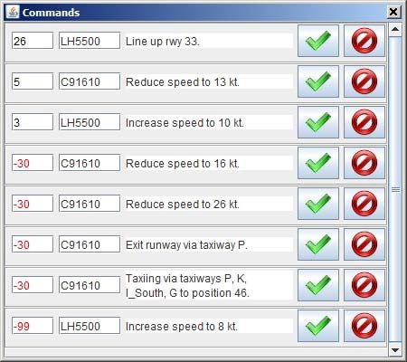
2
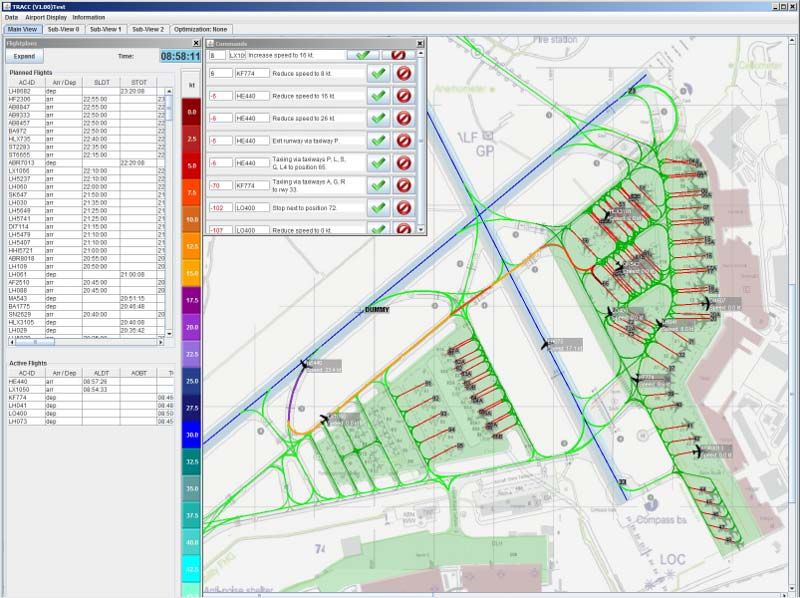
Figure 1. Main screen with view of the airport (map and node-link-system). Three sub screens for detailed views. Aircraft routes as colored lines
(color depending on average speed). Expandable Tables with information about planned and active aircraft. Frame with actual controller commands.
To take into account other requirements like a the used speeds of a route are not limited to the reference
minimization of delay, route length, or number of speeds, but the minimum speed for all links is five knots.
stops which should be considered within the route Holding times can only take place at nodes.
generation process
B. Principle of smallest modification
To present taxi routes and recommended taxi
instructions to the ground controller In comparison to other approaches [2], [7] the focus of
TRACC is on the single aircraft and the usage of the real
To solve pre-tactical (before arrival or push-back) airport structure for a direct adoption of the created routes. No
and tactical conflicts (conflicts between taxiing global optimum for all flights is created, because it must be
aircraft caused by constraint violation). expected, that several aircraft do not comply with the allocated
speed profile and need updated or new routes from time to
Taxi routes including push-back and line-up are created in
time also controller may change the route for a selected
advance and allocated to the aircraft before it starts the taxi
aircraft without interfering with the other. An important reason
process. The necessary taxi, push-back, and crossing
for the usage of a single aircraft approach is the complexity of
commands are created automatically from the generated route
the solution space for this problem. The objective of TRACC
(list of waypoints) and are presented to the controllers.
is not to find the optimal (global) solution for a group of
The main idea when developing TRACC was to work as aircraft, but a good and reliable (local) solution for a single
close as possible to the standard taxi processes. This includes aircraft which complies with the standard rules used for taxi
the assignment of a standard taxi route with standard speeds as routing and takes the other taxiing aircraft into account. These
start route and automatic identification and solving of push- rules include minimizing the number of speed changes and
back problems (pushing back in the route of an already taxiing stops and maintain a speed close to the reference speed as
aircraft). For this, a node-link system representing runways, often as applicable under the given circumstances. Calculating
positions, and taxiways underlie the airport. Nodes are used at a new global optimum every time an aircraft violates the taxi
taxiway intersections, stop-bars, line-up positions, parking constraints could lead to a higher number of re-routings for
positions and all other points of interest, whilst the links aircraft with correct taxi behavior which should be avoided.
represent the taxiways and are combined with a reference The optimization is carried out separately for each aircraft
speed as reference value for the optimization. Nevertheless, depending on the position in the optimization sequence.
Second SESAR Innovation Days, 27th – 29th November 20123
TRACC implements the “principle of smallest modification” as the DLR real time simulator. Afterwards, data needed by
where the routes should be as close as possible to a set of TRACC concerning the runway system (exits), taxi speeds,
standard routes and later changes of speeds or waypoints and push-back operations was added via ADEN (Airport Data
should occur as rarely as possible. Furthermore, only the Editor for NARSIM, [6]). As test case the structure of
aircraft which has violated the given taxi constraints should be Hamburg Airport was used together with an appropriate flight
penalized by a new, perhaps less appropriate route. schedule including scheduled and target times, used runway
and position, and aircraft type. Nevertheless, TRACC is a
Only the planned route (e.g. “taxi via taxiway a, b, c to
complete generic tool and does not depend on the selected
position A1...”) and the advisories for the next two waypoints
airport. Runway operations are privileged over taxi operations,
are shown to the controllers (see Figure 2). Actual speed
which are privileged over gate operations (Push-back, roll-
commands and clearances are published just in time (1 minute
through).
before activation). This way it is possible to avoid sending
redundant, confusing, or conflicting advisories. The optimization process for each aircraft starts depending
on the position of the aircraft in the optimization list not later
C. Optimization Sequence than 5 minutes before landing / push-back / roll-through. In
The optimization sequence list for all aircraft starts with a case of push-backs, a check for conflicts with already moving
sequence on “First Come, First Served” order in reference to aircraft is carried out and e.g. the push-back is delayed if
the TTOT (Target Take-off Time) and can be changed by a necessary to solve the conflict. The following optimization
controller or automatically if an aircraft needs to be re-routed. process can contain two different optimization algorithms
The planned speed and position of every active aircraft on the (speed and route optimization) depending on number and
airfield is known from NARSIM (NLR Air Traffic Control complexity of conflicts. After completion of the route creation
Research Simulator [10]) and is compared to the real position. process, the found technical route (list of way points) is
In case of deviations a conflict test is executed and if conflicts translated into a sequence of controller commands with time
occur with the adapted route a new route for the observed stamps (advisory list) for the publishing time (see Figure 2). In
aircraft is developed. For this, the routes of all other already accordance to the used node-link system only nodes can be
planned aircraft are taken into account, but are not subject to used as waiting points and speed changes are calculated as a
change. The most important problem is to guarantee safety linear change between two succeeding nodes. With the
under real time circumstances. activation of the aircraft the corresponding flight stripe is
moved from the table of the planned flights to the table for
active flights. Afterwards, the next planned position of this
aircraft is calculated for each time step and can be compared
to the actual position when working together with the real time
simulation environments.
E. Fields of Application
TRACC is designed to fulfill several different tasks in the
field of fast-time and real time simulations. As fully automatic
stand-alone simulation tool it can be used for testing new taxi
strategies (e.g. electric taxiing) or the possible influence of
new taxiways. The same can be carried out with controllers in
the loop. Furthermore, it can be used as a functional
complement on the ground for projects with 4D-trajectory
objectives or just as a generator of taxi commands or ground
traffic including arrival runway exit selection, push-back, and
line-up.
III. METHODOLOGY
A. Optimization Algorithms
TRACC has two different optimization algorithms in use,
Figure 2. Controller Command Panel. For each aircraft the time in both from the field of evolutionary algorithms. This type of
seconds until activation, aircraft-ID, command and accept and reject algorithm was selected because of the good experiences in the
buttons are shown. past when applying it to the creation of flight routes in the
TMA [3] or within a first approach to taxi planning [5]. The
D. Test Environment modular design of TRACC supports an easy exchange of the
For the implementation a basic data set of NARSIM was optimization strategy.
used. Therefore, TRACC works on the same node-link system
Second SESAR Innovation Days, 27th – 29th November 20124
The typical principles of evolutionary algorithms [4], [9] For aircraft on the runway system no conflict search with
are the closeness to the biological counterpart of normal other arriving, departing, or taxiing aircraft is carried out.
evolution. In nature, a group of individuals mix their genetic Instead the corresponding runway blocking times are
material, especially the information coded in chromosomes, to compared to the considered runway crossing times of all other
get better chances to survive in a hostile environment by a taxiing aircraft, which in case of conflicts have to wait in front
higher degree of adaptation. For an evolutionary algorithm, a of the runways until the runway can be crossed. The necessary
population of solutions for an artificial problem is coded as waiting time ends when an aircraft has passed the stop-
sequence of parameters (chromosomes) describing the position of the aircraft or an arrival has left the runway.
problem. Within TRACC the chromosomes consist of a
2) Conflicts between taxiing aircraft:
sequence of succeeding waypoints (nodes) together with speed
advisories. Aircraft movements are described as time dependent
As in nature, solutions can be mixed (so called cross-over, movements on a vector in a 2-dimensional space. For the
exchange of speed information or waypoints) or mutated conflict search for taxiing aircraft all links between succeeding
(speed change or introduction of a new waypoint). To waypoints of the observed routes are regarded as vectors in
guarantee the “Survival of the fittest” an evaluation function is space. Then the position of each aircraft can be described by
created which calculates an evaluation value for each solution the following formula:
based on how the parameter set fulfilled the given task.
Currently, this function takes the number of conflicts, distance
to target time, length of taxi route, number of speed changes (1)
and holdings into account but the observed parameters can be
exchanged easily. For the next generation only the fittest
solutions are selected and undergo the evolutionary operator’s with i = waypoint i, = Speed at waypoint i, i
crossover and mutation again until an appropriate solution is = Speed change per time unit at waypoint i , t = time
found. unit and = the reciprocal of the length of the link
The two algorithms used for TRACC differ in the scope of (directional vector) .
modification (genetic operators) and the evaluation function With this formula it is possible to calculate the minimum
which is applied to the same type of chromosomes. distance between two straight lines by solving a set of
The first one (TOA: Time Optimization Algorithm) works equations. Curves are approximated by a sequence of lines.
only on the speed part of the chromosomes and therefore is The boundary points where the aircraft leaves the link have to
much faster as the other algorithm which changes the routes be taken into account.
themselves (ROA: Route Optimization Algorithm). ROA has Furthermore, because the calculation of the minimum
to be aware of the problem to maintain the usability of a route distance for all combinations of route links between an
undergoing evolutionary operators. TOA is used for all aircraft observed aircraft and all other planned aircraft is very time-
as a first approach whilst ROA is used in more complex cases, consuming, a distinction of cases is done in advance. Special
where TOA was not able to create a conflict-free route or cases are e.g. no time overlapping, one or both aircraft wait.
when a conflict is caused by opposite traffic and therefore the Figure 3 shows two aircraft on their corresponding vectors
route has to be changed completely. For the optimization with the used part of the link between succeeding waypoints
process for each algorithm a different predefined number of colored in green and blue. The minimum distance between
generations is carried out in automatic mode. both aircraft on this link combination will take place at tmin2,
the last position of the blue aircraft on this link.
B. Conflict Detection
Three different types of conflict search are carried out, A conflict between an observed aircraft and another
depending on the status of the flights. These types are: aircraft is not counted as one conflict but the number of link
combinations of both routes where conflicts occur are
Conflicts between arriving / departing and taxiing calculated. This approach gives the algorithms the possibility
aircraft. to change stepwise to a conflict free route by reducing the
number of conflicting link combinations step by step.
Conflicts between taxiing aircraft and
3) Conflicts between aircraft pushing back and taxiing
Conflicts between aircraft pushing back and aircraft:
taxiing aircraft.
Taking into account the priority of taxiing over pushing
As is the rule in ATM, TRACC privileges runway
aircraft for each departure which tries to leave its position, the
operations over taxi operations, which are privileged over
same type of conflict search algorithm is used to calculate
Push-back-operations.
conflicts in the push-back phase. In case of a conflict, the
1) Conflicts between arriving / departing aircraft and pushing aircraft is delayed as long as necessary to avoid
taxiing aircraft: blocking the taxiway for all other aircraft. For test cases,
Second SESAR Innovation Days, 27th – 29th November 20125
Figure 3. Time dependent minimum distance between two aircraft moving on vectors in space.
TRACC possesses a second strategy where the push-backs optimization process. It is used for a problem dependent
start normally and the already moving aircraft are re-routed creation of holding points in more complex traffic situations,
using TOA and ROA. where the aircraft has to wait to avoid conflicts. When the safe
node is identified the part of the old route before the safe node
C. Safe Node Concepts is retained and a new route is created from the safe node to the
One of the most important tasks when managing taxy destination whilst the aircraft is moving on the remaining
operations is to solve suddenly evolving conflicts. There are fixed part of the route.
several situations where one has to be aware of them. An
example is, when departures reach the runway earlier than IV. RESULTS
expected, because this leads to changed runway blocking Because this tool is subject to ongoing research there is no
times and has therefore side effects on other aircraft which try comparison between real and simulation data available so far.
to cross this runway. Furthermore, changed routes for other Nevertheless, first test runs have been carried out to get an
aircraft can lead to new conflicts. Another potential conflict impression of the quality of the optimization results for both
situation arises if an aircraft doesn’t follow the instructions used Algorithms. As reference data for the traffic of a selected
and needs a new route whilst already taxiing. Therefore; two flight plan the values for conflicts, route length, target time,
questions are evolving: and delays without optimization process but based on standard
1. How much time do I have to solve the problem? routes are calculated and compared to the results when using
both optimization algorithms. As standard routes the shortest
2. Where should/can I start my optimization connections between start- and destination were used. These
process? routes use different standard speeds for taxi-area, apron,
Each optimization algorithm needs a special amount of runway exits, and positions and the only stops within these
time for the optimization task. So a value must be found which routes are situations where aircraft have to wait to cross an
guarantees an appropriate solution. In case of TRACC, a value active runway.
of 30 seconds is selected for unplanned situations. If the The used flight plan consists of 33 flights over a period of
conflict occurs within the next 30 seconds calculated from one hour with five minutes start-up phase for the simulation. It
actual time, an emergency stop is conducted and the aircraft includes several types of routing problems like “Crossing of
has to wait at a node before the conflict occurs until the other runways when another aircraft starts its take-off on this
aircraft has passed by. This additional stop can lead to runway”, “Push-back conflicts”, and “Taxi conflicts
conflicts with other aircraft, where again a reaction is (passing / opposite traffic)”. Five flights have conflicts when
necessary. no optimization is used and three flights undergo a revision of
Naturally, as stop node the waypoint before the position of the push-back time because of conflicts. Crossing of runways
the first conflict is calculated, but unfortunately, there are does not lead to conflicts because they are solved before the
situations where this is not enough. If two aircraft taxi in optimization process. For analyzing the results it is obvious,
opposite direction, the last node where they share the taxiway that the possible results of each single optimization task for an
and the minimum separation is maintained has to be identified. aircraft depend on the routes created for the previous flights.
The preceding node is then called “safe node” for the observed The optimization is carried out with a population size of 40
aircraft. And this “safe node” is the last possible starting point chromosomes (solutions) and a number of 500 populations for
of a new optimization process because it can be guaranteed TOA and ROA. Nevertheless, the goal for this simulation runs
that no conflict with the other aircraft takes place. As a start was not to find a global solution for all aircraft but to prove
node for the optimization the first waypoint before the safe the ability of TRACC to create conflict free, short, and
node is selected, which is more than 30 seconds away from the punctual routes which can be easily followed by pilots.
actual position. TABLE I shows the conflict data of the used flight plan
The safe node is calculated not only in conflict situations with five conflict situations. Each problematic aircraft has
but for all chromosomes of the population within the only conflicts with one other aircraft, but for a higher number
Second SESAR Innovation Days, 27th – 29th November 20126
of links. This results in a lack of separation of 282.7 meters for TABLE IV. DIFFERENCES BETWEEN THE RESULTS WHEN USING THE
all link combinations. STANDARD ROUTE IN COMPARISON TO THE ALGORITHMS OF
TRACC (STANDARD ROUTE – TRACC).
TABLE II shows the differences between TOA and ROA.
Difference between standard route and TRACC
Whilst TOA has the same route length and only the speeds are (standard – TRACC)
subject to change the route length for ROA increases a little Stops Taxi Delay Crossing Speed
bit when avoiding conflicts, but in return the punctuality [s] Delay [s] Changes
increases. Nevertheless both algorithms create routes which TOA 0.05 -0.2 2.0 1.8
ROA -0.03 -5.8 6.7 0.9
are more accurate than using the standard route.
TABLE III looks into the taxi times in more detail. The
average taxi times show combined values for arrivals and The results for ROA and TOA show significant differences
departures and the taxi times are close together for all which reflect the different approaches. The degree of freedom
algorithms. The resulting value for the difference to the for route creation is much higher for ROA caused by the
standard route is divided into arrival and departure taxi time possibility to change the route in addition to the speeds as in
differences and is shown in the last two columns. It can be case of TOA. Because for both algorithms the same simulation
seen that the highest difference takes place for the arrivals, for parameters were used (number of generations, chromosomes),
which the routes are longer and which have to cross the it was much harder for ROA to create good results, but they
departure runway 28 after landing on runway 32. The TRACC were comparable (pareto-optimal) to the results of TOA.
algorithms are able to change the speeds in such a way, that
the runway crossing delay (see TABLE IV) is shifted partly to V. OPERATIONAL CONTEXT
the taxi delay and the number of speed changes is As mentioned before, TRACC is part of the DLR project
considerably reduced in comparison to the standard route. flexiGuide, where it will be connected to AMAN and DMAN.
Furthermore, the results for the ROA algorithm are closer to This project has a timeframe until the end of the year 2013.
the target time than TOA, but this is bought by an increase for The development of TRACC should be seen as a research
the number of speed changes. An important result of these project which will create the basis for further investigation and
comparative simulation runs is that the TRACC algorithms are developments in this area. Within the SESAR context [11] it is
able to create short, conflict free, and punctual routes, which established in the key feature “Airport Integration and
are better than the set of standard routes with standard speeds Throughput” from “Deployment Baseline” to the 4D-concept
used for comparison. of “Step 2”. Nevertheless, it will consider aspects of
automation support tools for the airport as well. As important
prerequisite for 4D-taxiing, a better ability of the aircraft to
TABLE I. DATA FOR THE CONFLICTS OF THE USED FLIGHT PLAN. maintain a prescribed taxi-speed is identified, e.g. by electric
Avg. number Avg. number Avg. taxi.
of conflicting of conflicting summarized
link aircraft lack of
combinations separation VI. FUTURE WORK
[m]
Standard 7.16 1 -282.7 The most important step for the development of TRACC
Route will be the implementation of a control system which
compares planned and actual positions of taxiing aircraft and
TABLE II. DIFFERENCES IN MEETING THE TARGET TIME AND THE decides how to cope with identified problems. The decision
ROUTE LENGTH WHEN USING TOA AND ROA IN COMPARISON TO depends on the possible detection of conflicts as a result of
THE STANDARD ROUTE. constraint violations and leads to the creation of a new route
Difference to target Taxi route length [m] for the observed aircraft. Commonly, an algorithm has to be
time [s] created which is able to cope with unexpected situations like
Standard TRACC Standard TRACC Differ- usage of wrong speeds, wrong taxiway, or wrong exit or a
Route Route ence
TOA 10.4 7.9 2103.3 2103.3 0
non-cooperative aircraft.
ROA 10.5 6.9 2103.3 2104.6 -1.3 Furthermore, TRACC will become fully integrated inside
the DLR real time simulation environment where it will work
as stand-alone SMAN or in co-operation with other DLR tools
TABLE III. AVERAGE TAXI TIMES WHEN USING TOA AND ROA.
like AMAN and DMAN. Besides the possibility to test diverse
Average taxi times [s] Average taxi times procedures for ground movements or estimate the impact of
difference [s] new pavements for taxiways, parking positions, or runway
Standard TRACC Differ- Arrival Depart- exits, TRACC provides a reliable management of ground
Route ence ure movements that allows a better testing of the capabilities of
TOA 212.6 210.0 2.6 4.3 0.4
ROA 212.8 209.1 3.7 6.5 -0.2
DMAN and AMAN. Benefits created by those tools will not
be influenced by avoidable ground conflicts and delay.
Second SESAR Innovation Days, 27th – 29th November 20127
REFERENCES USA / Europe Air Traffic Management Research and Development
Seminar (ATM 2011).
[1] ACRP Report 62, “Airport Apron Management and Control Programs,
Airport Cooperative Research Program. [8] G.J.M. Koeners, E.P. Stout, R.M. Rademaker, “Improving Taxi Traffic
by Real-Time Runway Sequence Optimization using Dynamic Taxi
[2] Angel G. Marin, “Airport Management: taxi planning*”,Annuals of Route Planning”, Digigtal Avionics System Conference (DASC), 30 th
Operations Research Volume 143, Number 1 (2006), pp. 191-202. IEEEE / AIAA 2011, October 2011.
[3] Ingrid Gerdes, “Construction of Conflict-Free Routes for Aircraft in [9] M. Michalewicz, “Genetic Algorithms + Data Structures = Evolution
Case of Free-Routing with Genetic Algorithms”, ATM R & D Seminar Programs”, Springer, Berlin 1992, ISBN 3-540-60676-9
(EUROCONTROL), Saclay (Paris), July 1997
[10] NLR, “NARSIM”, www.narsim.org.
[4] I. Gerdes, F. Klawonn, R. Kruse, „Evolutionäre Algorithmen“, Vieweg
Verlag 2004, ISBN: 3-528-05570-7 [11] SESAR, “European ATM Masterplan”, Edition 2, SESAR, October
2012.
[5] Ingrid Gerdes, “GTRP: Generic Taxi Routing Program”, DLR,
[12] Saul Wordsworth, “Surface Watch”, Air Traffic Technology
Bibliotheks- und Informationswesen [Hrsg.]:, DLR-IB-112-2006/8,
International 2012.
2006.
[6] Ingrid Gerdes, “flexiGuide, ADEN (Airport Data Editor for NARSIM)”
, DLR, Bibliotheks- und Informationswesen [Hrsg.]:, DLR-IB-112-
2011/44,
[7] Yoon Jung, Ty Hoang, Justin Montoya, Gautam Gupta, Waqar Malik,
Leonard Tobias, “Performance Evaluation of a Surface Traffic
Management Tool for Dallas / Fort Worth International Airport, Ninth
Second SESAR Innovation Days, 27th – 29th November 2012You can also read


