QUANTAM/QUANTAM DENTAL 2019 BUILD PREPARATION SOFTWARE
←
→
Page content transcription
If your browser does not render page correctly, please read the page content below
Quick start guide
H-5800-1158-03-A

QuantAM/QuantAM dental 2019
build preparation software
© 2018 Renishaw plc. All rights reserved.

This quick start guide covers the Renishaw QuantAM/QuantAM dental build preparation software
version 2019.

This document may not be copied or reproduced in whole or in part, or transferred to any other media
or language, by any means, without the prior written permission of Renishaw.

The publication of material within this document does not imply freedom from the patent rights of
Renishaw plc.

Patents

Features of the Renishaw QuantAM/QuantAM dental build preparation software are the subject of one
or more of the following patents and/or patent applications:

 CN 105102160        CN 105228775           CN 105492981       CN 107206484        CN 107206493
 EP 2956261          EP 2956262             EP 3014369         EP 3221074          EP 3221075
 JP 2016/079495      JP 2016/079496         JP 2016/516886     JP 2016/517357      JP 2016/533571
 US 2016/079495      US 2016/079496         US 2016/0001401 US 2016/0370791 US 2017/0189961
 US 9669583          WO 2016/079496         WO 2014/125258     WO 2014/125280      WO 2016/079495
 WO 2016/193742      WO 2017/055853

Renishaw part no: H-5800-1158-03-A           First issued: January 2016      Revised: November 2018
Quick start guide

1 Disclaimer and trademarks
                                                                                                 1

1.1 Disclaimer
RENISHAW HAS MADE CONSIDERABLE EFFORTS TO ENSURE THE CONTENT OF THIS
DOCUMENT IS CORRECT AT THE DATE OF PUBLICATION BUT MAKES NO WARRANTIES
OR REPRESENTATIONS REGARDING THE CONTENT. RENISHAW EXCLUDES LIABILITY,
HOWSOEVER ARISING, FOR ANY INACCURACIES IN THIS DOCUMENT.

1.2 Trademarks
RENISHAW and the probe symbol used in the RENISHAW logo are registered trademarks of
Renishaw plc in the United Kingdom and other countries. apply innovation and names and
designations of other Renishaw products and technologies are trademarks of Renishaw plc or its
subsidiaries.

All other brand names and product names used in this document are trade names, service marks,
trademarks, or registered trademarks of their reactive owners.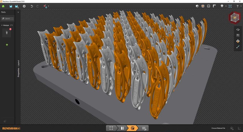
1.3 Warranty
             Equipment requiring attention under warranty must be returned to your equipment supplier.
Trade-mark
Disclaimer

             Unless otherwise specifically agreed in writing between you and Renishaw, if you purchased the
             equipment from a Renishaw company, the warranty provisions contained in Renishaw’s CONDITIONS
             OF SALE apply. You should consult these conditions in order to find out the details of your warranty
&

             but, in summary, the main exclusions from the warranty are if the equipment has been:
    2
             •    neglected, mishandled or inappropriately used; or

             •    modified or altered in any way except with the prior written agreement of Renishaw.

             If you purchased the equipment from any other supplier, you should contact them to find out what
             repairs are covered by their warranty.

             1.4 Changes to equipment
             Renishaw reserves the right to change equipment specifications without notice.
Quick start guide

2 Setup
                                                                                               3

2.1 Install and activate
1.   After you have purchased QuantAM 2019 you will receive an email from Renishaw.

2.   Follow the instructions in the email to install and activate Renishaw QuantAM 2019.

2.2 Configure
1.   The QuantAM 2019 software is preconfigured for Renishaw additive manufacturing systems.

2.3 Recommended PC specification
•    Processor CPU – 3.2 GHz (or better) multi-core CPU Intel Core i5 to i7 or higher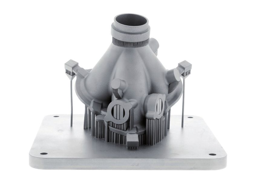
•    Operating system – Windows 7 SP1 64-bit Professional, Enterprise or Ultimate (32-bit is not
             supported) or Windows 10 64-bit

        •    Memory – 16 Gb RAM or better

        •    Hard drive – internal Solid State Drive (SSD) with 128 Gb of free space for processing
Setup

        •    Storage drive – as required by the number and size of build files you want to store
 4
        •    Monitor/display – minimum resolution 1280 X 1024 for HD 1920 x 1080

        •    Graphics card – NVIDIA GeForce GT 710 2 Gb RAM or higher (any graphics card supporting
             DirectX 9 and above)

        •    You will need sufficient local administrator privileges to enable you to install software

        Note: The QuantAM User interface can be used with a regular Windows compatible mouse and a
        space mouse.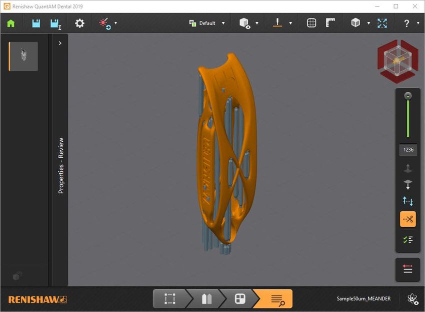
Quick start guide

3 The build preparation process
                                                                                                             5

3.1 Introduction
Using QuantAM 2019 to prepare your 3D data for an AM build is a very simple process with only a
few steps required to create a build file. If you are preparing a build file for a single laser Renishaw
AM system there are four stages of build preparation, and for a multi laser AM system there are five
stages.

1 – Orientation   2 – Support        3 – Layout         4 – Review         5 – Build file viewer
Position          Add support        Layout your        Review and         On multi-laser builds
your part in      to your model,     models on the      generate slices    assign lasers manually or
the optimal       where required     build plate        and scan paths     automatically, review and
orientation                                             for your model     create a renam build file

           Four stages must be completed for every AM build                  Optional fifth stage if using
                         preparation process                                  a multi laser AM system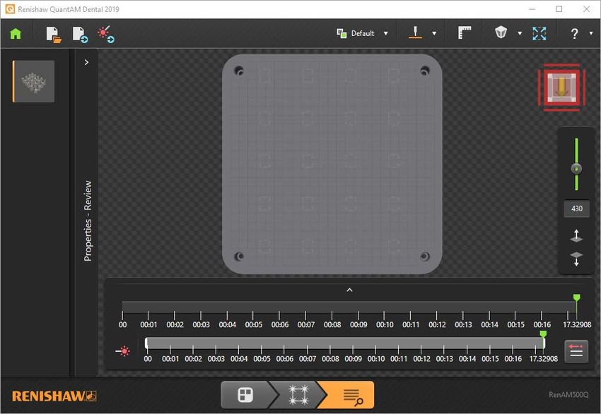
3.2 Build file formats
              QuantAM/QuantAM dental 2019 creates build files in two formats depending upon what type of AM
              system the part will be built on. If the part is to be built on a single laser Renishaw AM system the build
preparation
The build

              will be created as an mtt file. If the part is to be built on a multi laser AM system Renishaw AM system
process

              the build may also be created as a renam file. Renam is a Renishaw specific file format that includes
              all the attributes contained within an mtt file but with the addition of multi laser assignment information
    6         that does not fit within the specification of an mtt file.

              3.3 Training
              Renishaw can provide a range of training courses from basic through to advanced to assist you in
              getting the best out of QuantAM 2019 and QuantAM 2019 Dental. Use the contact details information
              in Section 5 to contact Renishaw and discuss the range of options available.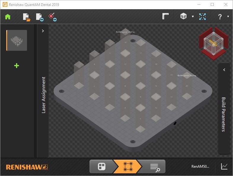
Quick start guide

4 User interface
                                                                                            7

4.1 Introduction
The User interface of QuantAM/QuantAM dental 2019 is described in the following sections:
4.2    Start page
4.3    Generic QuantAM functions
4.4    Stage 1 of build preparation – Orientation
4.5    Stage 2 of build preparation – Support
4.6    Stage 3 of build preparation – Layout
4.7    Stage 4 of build preparation – Review
4.8    Build file viewer
4.9    QuantAM 2019 Dental
4.10   Keyboard shortcut keys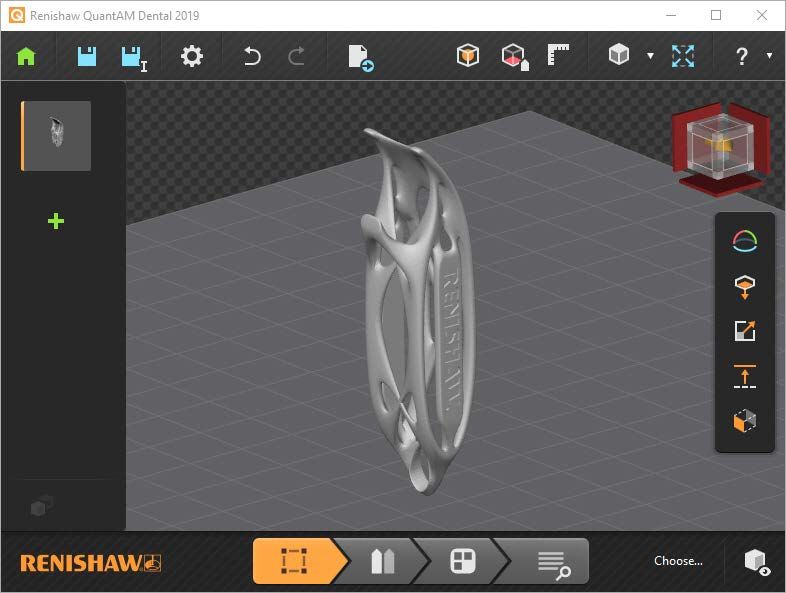
Quick start guide

            4.2 Start page
interface

             1     2                    3 4
User

  8

                                6   5
1 Start or Navigate to 3D View
Returns you to the 'Start page'. When on the 'Start page' an arrow is
displayed 'Navigate to 3D View' select it and you will return you to the 3D
View.
interface
2 Settings
User
Enables you to control various parameters of the build, including 'Build',
'Support', 'Miscellaneous' and if purchased, 'Dental'. Within 'Build' you
can select the type of Renishaw AM system the part will be built on and 9
the build volume size. The selection of AM systems includes AM 250,
AM 400, RenAM 500M and RenAM 500 series multi laser. The choice of
build volume includes default or Reduced Build Volume (RBV). If you have
purchased a QuantAM Dental licence, within 'Dental' you can enable the
functionality and enable or disable various parameters, see Section 4.9.
3 Help User (F1)
Launches the Quick Start Guide. Also launches from the four stages of
build preparation.
4 About QuantAM
Displays product licence and trademark information about the Renishaw
QuantAM software. Also launches from the four stages of build preparation.5 Open
Opens a dialog which enables you to choose from an existing workspace
containing either, Parts as stl files, Projects as amx files or Scan paths as
mtt or renam files. Choosing and opening a Scan path (mtt or renam file)
interface
will open Build File Viewer, (see Section 4.8), this enables you to rapidly
prepare a build with the file selected, for example where you only wish to
User
make minor revisions to the build file before starting your build.
10 6 New
Opens a new blank workspace, into which you can select and import CAD
data of the following types amx, catpart, cli, ctm, prt, sab, sat, sldprt, step,
stl, stp, x_b or x_t.Quick start guide
4.3 Generic QuantAM functions
interface
1 2 3 4 5 6 7 8 9 10
User
12
18
11
17
13 14 15 16 12Note: The Generic QuantAM functions are the functions that are available at all four stages of the build
preparation process. All four stages of the build preparation process have functions that are specific to
that stage, and each stage and the its functions are described in the following sections.
interface
Note: All Ctrl + [number] shortcuts refer to keyboards with a number pad. For users without a number
User
pad, such as laptops, use Ctrl + Windows key + [number].
13
1 Navigate to Start Page
Returns you to the 'Start page'. When on the 'Start page' an arrow is
displayed 'Navigate to 3D View' select it and you will return you to the 3D
View.
2 Save (Ctrl + S)
Saves the project (scan path, model and support) as a QuantAM Project
File, an amx file in a location of your choice.
3 Save As (Ctrl + Shift + S)
Saves a copy of the project (scan path, model and support) as a QuantAM
project file, an amx file, in a location of your choice.4 Settings
Enables you to control various parameters of the build, including 'Build',
'Support', 'Miscellaneous' and if purchased, 'Dental'. Within 'Build' you
can select the type of Renishaw AM system the part will be built on and
interface
the build volume size. The selection of AM systems includes AM 250,
AM 400, RenAM 500M and RenAM 500 series multi laser. The choice of
User
build volume includes default or Reduced Build Volume (RBV). If you have
14 purchased a QuantAM Dental licence, within 'Dental' you can enable the
functionality and enable or disable various parameters, see Section 4.9.
5 Undo (Ctrl + Z) and Redo (Ctrl + Y)
Enables you to 'Undo' the last action and revert to the previous state.
'Redo' enables you to redo the previously undone action.
6 Export (Ctrl + E)
The options to export are, 'Only Part (Cluster)', 'Only Support', 'Both Part
and Supports' and 'Exposures'. Export only available in the 'Orientation'
and 'Support' stages of build preparation.
7 Show/Hide 2D Measurement (K)
Enables you to see a ruler around the edge of the build plate window. The
ruler will be in the units of your choice, mm or inches.8a Perspective View (Ctrl + 8)
Perspective view – the rendering is optimised to give a more natural view
of the model. Toggle between the two views using the shortcut.
8b Orthographic View (Ctrl + 8)
interface
Orthographic view – the model is represented with right angles and parallel
lines. Toggle between the two views using the shortcut.
User
9 Zoom to Extents (Ctrl + 0)
Zooms out to fit the entire part to be built into the available window. 15
10 Help User (F1)
Select the question mark and the Quick Start Guide will launch. Select the
down arrow and this displays a flyout with a choice of two Help options,
'Help User (F1)' (10a) and 'Keyboard Shortcuts (Ctrl + F1)' (10b).
10a Help User (F1)
Launches from all four stages of build preparation in a flyout. Displays the
QuantAM Quick start guide. You can browse or search for the information
you want.
10b Keyboard Shortcut (Ctrl + F1)
Launches from the four stages of build preparation in a flyout and displays
six grouped lists of keyboard shortcuts. See Section 4.10 for details.11 Navicube
Enables you to rotate the view of the part around as you wish. You can
select predetermined views by selecting the edges, corners and planes
of the Navicube. Alternatively, you can select and drag the Navicube to
interface
display a view to suit your needs. Ctrl + 9 enables you to toggle between
the Navicube views to select the view you want (edges, corners or planes).
User
The direction of the orange arrow identifies the front of the build plate.
16 12 Choose Material File
Enables you to chose the material file you want for your build. Once the
material file is chosen, you can view several tabs containing information
about the material file selected. Tabs include 'Slicing', 'Hatching', 'Order'
and 'Scanning'. You can also use the drop down to change the selected
material file and associated parameters.
13 Orientation
The first stage of the build preparation process. Position your part in the
optimal orientation to ensure the best quality build and surface finish.
14 Support
The second stage of the build preparation process. Add support to your
model, where required, to enable it to be successfully built.
15 Layout
The third stage of the build preparation process. Layout your models on the
build plate to maximise the available space for your build.16 Review
The fourth stage of the build preparation process. In Review you generate
slices and scan paths for your model before it is sent to the AM system.
17 Import CAD data
interface
Opens the 'Import model' dialog which enables you to select the CAD data
you wish to import (stl, amx, ctm, sat, sab, x_t, prt, stp, step, x_b, sldprt,
User
iges or igs files) into the workspace.
18 Model thumbnail 17
Displays a thumbnail of the model files open in the workspace. The orange
shadow indicates that the model file is selected.
Note: It is also possible to import files by dragging and dropping them on to the 'Import CAD data'
button.Quick start guide
4.4 Stage 1 of build preparation – 'Orientation'
interface
1 2
User
18
3
4
5
6
7
9 81 Show/Hide Bounding Box (B)
Enables you to see a bounding box around the model. A bounding box
helps you position a model on the build plate and avoid collisions between
closely spaced parts. This function is available in the Orientation and
interface
Layout stages of build preparation.
2 Show/Hide Support Region Colour (C)
User
Indicates regions on the part that QuantAM determines needs support
adding. Regions highly likely to require support are coloured red and 19
regions that may require support are coloured yellow. This function is
available in the Orientation and Layout stages of build preparation.
3 Part Orientation (O)
Enables you to tilt and rotate the model relative to the build plate before
supports are added. Values can be added in degrees or dragged.
4 Select Downward Surface (D)
Enables you to select part of the models surface, and set it as the
downward facing surface nearest the build plate.
5 Scale Part (X)
Enables you to scale the model. This enables easy upscaling of the part
without going back to the CAD data.6 Z Offset (Q)
Enables you to define the Z offset between the model and the build plate. Z
offset gives sufficient distance for suitable supports to be added.
7 Extrude
interface
This enables you to extrude part of your model. This can be useful when
small adjustments need to be made to a model without having to go back
User
to the original CAD model, such as adding a build plate removal allowance.
20 Select the area of the model you wish to adjust, enter the distance you
want to adjust it by and select 'Apply'.
8 Part Cluster Viewer
This opens the 'Part Cluster Viewer' which displays information about the
imported part including, 'Part Cluster ID', 'Part Name', 'Type', 'Status', and
X, Y and Z position. Within 'Part Cluster Viewer' there are two buttons, 'Add
Part to Cluster' and 'Delete'. Each part imported will be added to the cluster
and treated as one part for supporting and slicing.
9 Orientation Stage
The first stage of the build preparation process. Position your part in the
optimal orientation to ensure the best quality build and surface finish.
Note: In the Orientation stage of the build preparation process, if you right-click on the selected model
thumbnail, a context sensitive menu will open. The context sensitive menu displays options for the
model, see the screen shot below.interface
User
21
Note: In the Orientation and Support stages of the build preparation process, if you select the H
keyboard shortcut, QuantAM will highlight the areas where small features are present. This is shown in
the screen shot below where the small features of the Renishaw logo are highlighted in black.Quick start guide
4.5 Stage 2 of build preparation – 'Support'
interface
1 2 3
User
22
4
5
6
7
8
9
10
13 12 111 Export (Ctrl + E)
In the 'Support Stage' this enables you to export 'Only Part, 'Only Support',
'Both Part and Supports' or 'Exposures'. Select the button, this opens the
'Export' dialog where you can choose what to export, select Ok, navigate
interface
to the location where you wish to export to and select Ok.
2 Import Supports (Ctrl + I)
User
Enables you to import externally generated support files in ctm or stl files.
Select the button, this opens the 'Import supports' dialog, select the supports 23
you want to import and select 'Ok'.
3 Section (V)
Enables you to section the active model, to ease the process of adding
support. Selecting 'Section' will display a flyout with three selections
available 'Clip All' (Ctrl + K), 'Clip Part only' (Ctrl + K) and 'Clip Supports
only' (Ctrl + K). Selecting the arrow (it turns from grey to blue) will enable
you to drag the section up or down as required. Double clicking the arrow
will reverse the direction of the section.
4 Auto Generate Point Supports (A)
Enables you to automatically generate point supports for the model.
Progress is displayed on-screen in a progress indicator.
5 Enable/Disable Point Supports (P)
Enables you to generate point support from a user defined point on an
overhanging surface of the model.6 Enable/Disable Line Supports (L)
Enables you to define and generate a line of grouped supports under the
model.
7 Enable Region Selection (G)
interface
Enables users to specify areas where support material is required, rather
than support material being applied to all downward facing surfaces. It
User
enable users to apply different support strategies to specific regions. It
24 can be used in conjunction with the 'Show/Hide Support Region Colour'
tool (C) and the 'Region Viewer' (R) to apply support exactly where it is
required. A slider enables you to select a value between 0 and 15, where 0
is no support and 15 will be support applied to all supportable surfaces.
8 Support Selection
Enables you to select supports. Selecting it will display a flyout with three
selections available 'Select All Supports' (Ctrl + A), 'Select Supports
Intersecting with Part' (Ctrl + Alt + P) and 'Select all Intersecting Supports'
(Ctrl + Alt + A).
9 Support Edit Mode (M)
Select a support and 'Support Edit Mode', this highlights the support and
displays a control with three axis around it. The control allows you to drag
the support around in three dimensions to achieve the support orientation
you want.10 Display Slices (S)
This enables you to view the model and support slices whilst remaining
in the 'Support Stage'. Generating slice progress is displayed on-screen.
If you select 'Display Slices' and have not specified a material file you
interface
will be prompted to do so before the slices are generated. Once slices
are generated slice controls will be displayed, these are a slider to drag
User
the displayed slice up or down, the slice number, 'Go to Next Layer', 'Go
to Previous Layer', 'Flip Clipped Region', 'Show/Hide Clipped Region', 25
'Update Slices' and 'Slice Properties'. See Section 4.7 for details of these
functions.
11 Region Viewer (R)
Selecting this displays the 'Region viewer' tools. This enables you to have
different support strategies for different regions of a part and to manage,
edit and delete these regions. These tools can be floating or docked.
12 Support Stage
The second stage of the build preparation process. Add support to your
model, where required, to enable it to be successfully built.
13 Properties – Support
Enables you to set parameters for generated support. Select anywhere
on the 'Properties – Support' bar to open the flyout menu and select the
chevron at the top to close it. Parameters such as support thickness,
'Cross Section', 'Cluster Support Settings' and 'Support Type' can be
edited as required.Note: If a support is blue, the support is not intersecting the part or another support. Dark blue is an
isolated internal support and light blue is an isolated substrate to part support. If the support is red
the support is intersecting another object. Dark red is intersecting the part and light red is intersecting
another support.
interface
User
Note: In the Support stage of the build preparation process, if you select an individual support and
26 right-click, a context sensitive menu will open. The context sensitive menu displays options for the
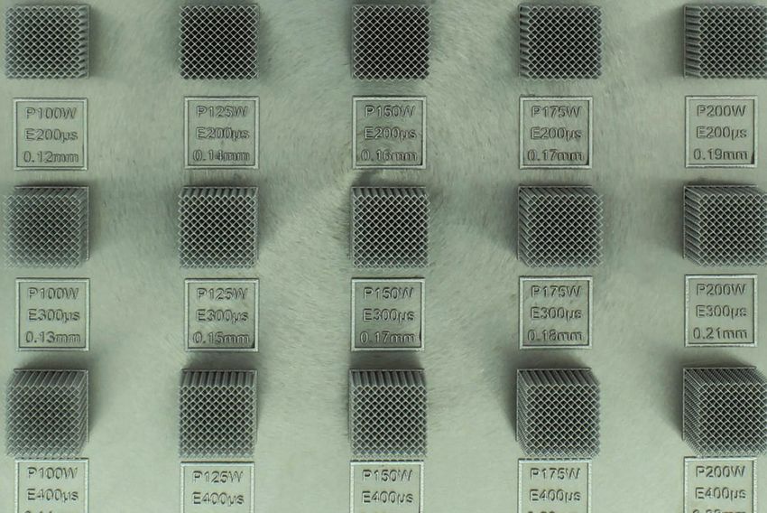
selected part and supports, see the screen shot below.Test builds of mesh, built in aluminium, in varying thicknesses and using a variety of parameter settings.
Quick start guide

            4.6 Stage 3 of build preparation – 'Layout'
interface

                                 1       2 3 4
User

 28

                                                                 5
                                                                 6
                                                                 7
                                                                 8

              14        13 12         11                  10 9
1 Export MTT (Ctrl + E)
Select the 'Export' symbol and the 'Export MTT File' dialog will display. If
no material file has been selected, the 'Material Details' dialog will open
and enable you to select a material and scanning strategy for your build.
interface
Select the down arrow and a flyout with three selections will be displayed,
'Export MTT' (Ctrl + E), 'Export STL' and 'Export Other'. Select 'Export
User
STL' and the 'Export' dialog will display and ask you to select what you
want to export. Selecting 'Export Other' opens the 'Export JPEG File' 29
dialog and enables you to save a JPEG of your build.
2 Show/Hide Silhouette (U)
A simple On/Off button to show or hide the silhouette of the model on the
build plate beneath the selected model.
3 Show/Hide Bounding Box (B)
Enables you to see a bounding box around the model. A bounding box
helps you to position a model on the build plate and avoid collisions with
adjacent models.
4 Show/Hide Build Plate (H)
A simple On/Off button to show or hide the build plate beneath the
selected model.
5 Rotate Part (R)
Enables you to rotate the selected model on the build plate. Drag and drop
to the angle you want using the angular display in degrees, or enter the
angular value you want and select enter.6 Instancing (I)
Enables you to make multiple copies of the selected model and place them
a user defined distance apart in X and Y axis on the build plate. Select your
part and either drag the arrow to create multiple instances of the selected
interface
model or use the 'Instancing' dialog to define how many copies of the
model you want on the build plate in rows and columns.
User
7 Nesting (N)
30 This enables you to define the spacing between instances of a part on
a build plate. Select the parts, open the 'Nesting' dialog, enter a suitable
value equating to the distance you want between parts and select 'Apply'.
8 Translation (Y)
This enables you to move parts by 'Absolute' or 'Relative' amounts across
the build plate in a more precise way than dragging. Select the 'Translation'
button, select 'Absolute' or 'Relative' enter the values you wish to move the
parts by in X and Y axis and select 'Apply'. The X and Y position of a part
is also displayed in 'Material viewer' under the 'General' tab and can be
edited in a csv file of the material parameters.
9 Build Plot Viewer (Ctrl + P)
Select this and a graph with 'Total Number of Layers' and 'Cross Sectional
Area in mm² will be displayed. A graphic distinction between the amount
of combined build and the amount of support in the build is shown in the
graph.10 Material viewer
Enables you to view several tabs containing information about the build.
The tabs include 'General', 'Strategy', 'Control', 'Order', 'Volume', 'Upskin',
'Downskin', 'Scan Volume', 'Scan Upskin', 'Scan Downskin', 'Scan
interface
Exposures' and 'Shrinkage Factors'. There are buttons to enable you to
'Import a CSV File (Ctrl + I)', 'Export the Selected Tab to CSV File' or
User
'Export All to CSV File (Ctrl + E)'. These tools can be floating or docked.
This also enables you to select a different material for each part. 31
11 Layout
The third stage in the build preparation process. This enables you to layout
the models on the build plate.
12 Layout Viewer
In the Layout stage you can create more than one layout for the part. Each
layout can have a different material file. All layouts will be saved in the
same QuantAM project file .amx. Layout Viewer can be docked or floating.
13 Properties – Layout
Enables you to view parameters for the layout. Select anywhere on the
'Properties – Layout' bar to open the flyout menu and select the chevron to
close. Parameters including 'Part Name', 'Part ID', 'Part Z Height', 'Number
of Layers', 'Part Volume' and Total Support Volume' can be viewed.14 Show/Hide Current Layout Parts
This toggles to show either all of the parts saved in the amx project file or
only those in the current view.
interface
Note: In the Layout stage model(s) can be re-positioned on the build plate by selecting the model,
User
holding the Alt key and dragging the model to the desired position. In the Layout stage the front edge
of the build plate, nearest the AM system door, is identified by a black dot.
32Quick start guide
4.7 Stage 4 of build preparation – 'Review'
interface
1 2 3
User
34
4
5
6
7
8
9
10
11
14 13 121 Theme (Ctrl + T)
In the 'Review' stage of build preparation, this enables you to change the
colour theme for the scan path and layers according to preference. There
are four schemes to choose from.
interface
2 View Part and Layer (Ctrl + J)
'View Part and Layer' enables you to toggle between 'View Part and Layer'
User
or 'View only Layer'.
3 Exposure Lines (Ctrl + H) 35
Enables you to toggle between a view the scan path as 'Exposure Lines',
'Exposure Points' or as an 'Energy Density Map'. In an 'Energy Density
Map' red indicates areas of high energy density and green indicates areas
of lower energy density.
4 Slider bar pointer
Enables you to move the slice point through the build. Select and drag the
slider to the slice you want to see, the slice number is displayed below the
slider. Any slice or heal errors will be shown in red.
5 Slice number indicator
Displays the slice number you are currently viewing. Select the number,
type the slice number you wish to see and select 'Return' to display the
slice requested.6 Go to Next Layer
Shows the 'Next Layer' up in the section.
7 Go to Previous Layer
interface
Shows the 'Previous Layer' down in the section.
User
8 Flip Clipped Region
36 Reverses the direction of the visible model in the cut plane progression,
not available for a transparent model.
9 Show/Hide Clipped Region
Enables you to toggle between viewing the transparent model and the
solid model, with the section plane highlighted.
10 Slice Properties
Selecting this opens the 'Slice Properties Viewer' and displays information
about the build including the 'Layer No.', 'Z offset' and 'Healed'. It will also
display how many slices of the build require healing to rectify any errors in
the imported data without the requirement to edit the original 3D data.
11 Steps through the Scan Blocks (F2)
This enables you to step scan line by scan line through each layer of a
build. A scroll bar enables you to see the order and sequence of each
scan line. Drag the slider to show the position of the laser, or use the arrow
buttons for 'Previous Move' and 'Next Move'. Whilst dragging the slider an
info box will display the scan number, X and Y position, length of next scan
and length of previous scan.12 Material Details
Enables you to select the material file you want for your build. Once the
material file is selected, you can view several tabs containing information
about the material file selected. Tabs include 'Slicing', 'Hatching', 'Order'
interface
and 'Scanning'. You can also use the drop down to change the selected
material file and associated parameters.
User
13 Review
The fourth stage in the build preparation process. The tools in review 37
enable you to review slices and scan paths for the build before exporting
the build as an mtt build file.
14 Properties – review
Enables you to view individual parameters of the properties. Click
anywhere on the bar to open the flyout menu and click the chevron to
close it. Information including 'Build Time', 'Total Costs', 'Build Information',
'Machine Information', 'Build Parameters' and 'Cost Parameters' can be
viewed.Quick start guide
4.8 Build file viewer
interface
User
4.8.1 Introduction
38
If you are creating a build for a Renishaw multi laser AM system you will need to complete one
additional stage of build preparation before you can start your build.
From the 'Start' page, see Section 4.2, select 'Open', navigate to the location where your mtt build file
is located, select the mtt file and open it.
The 'Build file viewer' has three stages, 'Layout', 'Assignment' and 'Review'.
In 'Layout' you can make any changes needed to the angular position and X and Y positions of the
slice files in your build. You can also combine mtt files.
In 'Assignment' you can select and assign lasers to the parts in your build. This can be done
automatically by QuantAM or manually utilising your skills and knowledge of how to prepare a build.
In 'Review' you can check the laser assignment by reviewing the build layer-by-layer and scan line by
scan line through each layer. When the review is complete export the build file to either mtt or renam
format ready to be built on a Renishaw multi laser AM system.4.8.2 Stage 1 of Build file viewer – Layout
interface
1 2 3
User
40
4
5
7 61 Import Parameters CSV (Ctrl + I)
In 'Build File Review', this enables you to import your own set of
parameters, in csv format, that have been developed outside of QuantAM
e.g. in Renishaw Materials Editor or MS Excel.
interface
2 Export Parameters CSV (Ctrl + E)
In 'Build File Review', this enables you to export your parameters in csv
User
format. This enables you to edit your parameters using tools such as MS
Excel or Renishaw Materials Editor. 41
3 Export MTT/RENAM (Ctrl + M)
In 'Build File Review', this enables you to export your build file as either an
mtt file for building on a single laser Renishaw AM system or as a renam
file for building on a multi laser Renishaw AM system.
4 Rotate Part (R)
Enables you to rotate the part about its centre. Select the part, select the
'Rotate' button, either enter the rotation value manually or drag the part to
the desired angle.
5 Translation (Y)
Enables you to move the part in 'Absolute' or 'Relative' terms. Select the
part you wish to move, select the 'Translation' button, select 'Absolute' or
'Relative', enter the X and Y values you want and select 'Apply'.6 Build Settings
This displays the currently selected Renishaw AM System. The model of
AM system selected affects parameters within the build. Select the button
and a menu will display where you can select the Renishaw AM system
interface
type and build volume size you want to build in.
7 Layout Stage
User
This is the first stage of the 'Build file viewer' process where the layout of
42 part can be adjusted as required before moving to the 'Assignment Stage'.
Note: In the Layout stage of 'Build file viewer' if you select two or more mtt files and right-click, a
context sensitive menu will open. The context sensitive menu enables you to merge the selected mtt
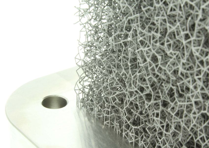
files, see the screen shot below.Central Titanium Support (CTS) from the ARION4 project run by the University of Liverpool Velocipede Team (ULV Team), in which Karen Darke and Ken Talbot set world speed records for hand cyclists at the World Human Powered Speed Challenge at Battle Mountain, Nevada, USA.
4.8.3 Stage 2 of Build file viewer – Assignment
interface

                            1
User

 44

                                                                  2

                                            4                 3
1 Laser Assignment
Selecting 'Laser Assignment' opens a flyout menu which enables you to
make choices about which laser you want to assign to each part. This can
be done automatically by QuantAM or manually utilising your skills and
interface
knowledge of how to prepare an AM build. Within 'Laser Assignment' are
controls to:
User
'Apply to Defaults' – apply the selected automatic laser assignment only to
unassigned (default – grey) parts. It maintains manual pre-assignment. 45
'Apply' – apply the selected auto assignment to all parts, this will overwrite
any manual selection.
'Reset to Defaults' – clear all selections, or all selected.
2 Build Parameters
Select a part, select the 'Build Parameters' menu and a flyout menu will
display. The menu will display parameters about the selected part including
'Continuous Laser' on/off, 'Laser Power', 'Laser Focus', 'Laser Speed',
'Point Distance', 'Exposure Time', 'Point Jump Display', etc.
3 Laser Plot Viewer (Ctrl + P)
Selecting this displays a graph showing the number of layers against the
laser scanning time for the layer. The 'Sampling Step' can be adjusted as
required.
4 Assignment Stage
This is the second stage of the 'Build file viewer' process where lasers are
assigned to your part before moving to the 'Review Stage'.4.8.4 Stage 3 of Build file viewer – Assignment
interface
1 2 3
User
46
4
5
6
7
8
11 10 91 Laser Assignment
Selecting 'Laser Assignment' opens a flyout menu which enables you to
make choices about which laser you want to assign to each part. This can
be done automatically by QuantAM or manually utilising your skills and
interface
knowledge of how to prepare an AM build. See Section 4.8.3.
2 Theme (Ctrl + T)
User
In the 'Review' stage of build preparation, this enables you to change the
colour theme for the scan path and layers according to preference. There 47
are four schemes to choose from.
3 Exposure Lines (Ctrl + H)
Enables you to toggle between a view the scan path as 'Exposure Lines',
'Exposure Points' or as an 'Energy Density Map'. In an 'Energy Density
Map' red indicates areas of high energy density and green indicates areas
of lower energy density.
4 Slider bar pointer
Enables you to move the layer through the build. Select and drag the slider
to the layer you want to see, the layer number is displayed below the slider.
5 Layer number indicator
Displays the layer number you are currently viewing. Select the number,
type the layer number you wish to see and select 'Return' to display the
layer requested.6 Go to Next Layer
Shows the 'Next Layer' up in the section.
7 Go to Previous Layer
interface
Shows the 'Previous Layer' down in the section.
User
8 Steps through the Scan Paths
48 This enables you to step scan line by scan line through each layer of a
build. Selecting this will open two time based scroll bars that enable you
to see the order and sequence of each scan line of each layer of the build.
The lower bar is coarse and the upper is fine. Drag the slider to show the
position of the laser on the layer, or use the arrow buttons for 'Previous
Move' and 'Next Move' to move between layers. Drag the ends of the lower
bar to increase or increase the fidelity of the upper bar.
9 Build style viewer
Enables you to view build styles and parameters. Click anywhere on the
bar to open the flyout menu and click anywhere to close it. Information
including 'Laser', 'Build Style', 'Element ID', 'Focus', 'Power', 'Point
Distance', 'Exposure Time', 'Point Jump Delay', 'Jump Speed' and 'Jump
Delay' will be displayed. As you scroll though the layers the build style and
parameters will change.10 Review Stage
This is the third stage of the 'Build file viewer' process where the laser
assignment can be checked and adjusted as necessary. When the review
is complete, export the build file to renam format ready to be built on a
interface
Renishaw multi laser AM system.
11 Laser Options
User
Selecting 'Laser Options' opens a filtering dialog where you can select
which laser you wish to view that path of in 'Steps through the Scan Paths'. 494.9 QuantAM 2019 Dental
interface
1 2 3 4 5
User
50
6
8 7Note: If you have purchased a QuantAM Dental licence, from 'Settings', 'Dental' you can select the
functionality you want to enable and disable using toggles.
interface
1 Dental Plugin
User
This enables you to toggle 'On' or 'Off' the Dental features within QuantAM
Dental 2019.
51
2 Auto Orientation
This enables you to toggle 'On' or 'Off' the 'Auto Orientation' feature for
parts imported into QuantAM Dental.
3 Auto Nesting
This enables you to toggle 'On' or 'Off' the 'Auto Nesting' feature for parts
imported into QuantAM Dental.
4 Auto Tag Creation
This enables you to toggle 'On' or 'Off' the 'Auto Tag Creation' feature for
parts imported into QuantAM Dental. Tags can be printed next to each part
to enable you to easily identify parts visually. Within QuantAM Dental tags
can be searched for to enable you to locate where on a build a specific part
is located.
5 Auto Support Generation
This enables you to toggle 'On' or 'Off' the 'Auto Nesting' feature for parts
imported into QuantAM Dental.6 Default Support Style
This drop down enables you to choose whether you want fine, medium,
coarse or MDPD_1mm supports for your build.
7 Ok/Cancel
interface
Select to confirm the selection or Cancel and return to the previous screen.
User
8 Dental
Select this to open the dental drop down and see the range of functionality
52 you want to enable and disable
Note: In QuantAM Dental 2019 when you select 'Import CAD data', the 'Import model' dialog will open
but the range of file types that can be imported is reduced. Only amx, ctm and stl files can be imported
into the workspace.4.10 Keyboard shortcuts
interface
User
Note: All Ctrl + [number] shortcuts refer to keyboards with a number pad. For users without a number
pad, such as laptops, use Ctrl + Windows key + [number].
53
There are six groups of keyboard shortcuts. They are as follows:
1 Mouse Control – Section 4.10.1. 2 Common Shortcuts – Section 4.10.2.
3 Orientation Stage – Section 4.10.3. 4 Support Stage – Section 4.10.4.
5 Layout Stage – Section 4.10.5. 6 Review Stage – Section 4.10.6.
The six groups are described in the following sections.
4.10.1 Mouse Control
Scene Rotation – Left Button Pan Operation – Right Button
Zoom Camera – Mouse Scroll4.10.2 Common Shortcuts
Fit to Screen – Ctrl + 0 Top View – Ctrl + 1
Bottom View – Ctrl + 2 Front View – Ctrl + 3
interface
Back View – Ctrl + 4 Left View – Ctrl + 5
User
Right View – Ctrl + 6 Isometric View – Ctrl + 7
Toggle Orthographic/Perspective View – Ctrl + 8 Toggle Navicube Style – Ctrl + 9
54
Save Active Build – Ctrl + S Rectangular Zoom – Z + Left Click + Drag
To Escape from Selected Function – Esc Show/Hide 2D Measurement – K
Keyboard Shortcuts – Ctrl + F1 Import Model – Ctrl + O
4.10.3 Orientation Stage
Part Orientation – O Set Downward Surface – D
Scale Part – X Change Z Offset – Q
Extrude Part – E Show/Hide Bounding Box – B
Show/Hide Support Region Colour – C Model Transparent/Opaque – T
Wireframe – W Hard Edges – H
Undo – Ctrl + Z Redo – Ctrl + Y
Export Part – Ctrl + E4.10.4 Support Stage
Auto Supports – A Auto Minima Supports – M
Enable/Disable Point Support Mode – P Enable/Disable Line Support Mode – L
interface
Region Selector – G Select all Supports – Ctrl + A
User
Select all Intersecting Supports – Ctrl + Alt + A Select all Part Intersecting Supports – Ctrl + Alt + P
Support Edit Mode – M Slicing – S
55
Section – V Region Viewer – R
Show/Hide Support Region Colour – C Toggle Support Clipping Options – Ctrl + K
Select/Deselect Multiple Instances – Ctrl + Left Enable/Disable Line Support Mode – Right
Click Button Click
Delete Support – Delete Translate Supports – Alt + Left Click + Drag
Model Transparent/Opaque – T Wireframe – W
Hard Edges – H Undo – Ctrl + Z
Redo – Ctrl + Y Export Parts/Supports – Ctrl + E
Import Supports – Ctrl + I4.10.5 Layout Stage
Hide Substrate – H Show/Hide Bounding Box – B
Show Silhouette – U Show Rotation Tool – R
interface
Instancing – I Nesting – N
User
Translation – Y Copy – Ctrl + C
Paste – Ctrl + V Select/Deselect Multiple Instances – Ctrl + Left
56 Click
Move Part – Alt + Left Click + Drag Delete Instance – Delete
Undo – Ctrl + Z Redo – Ctrl + Y
Export MTT – Ctrl + E Select all Instances – Ctrl + A
Material Viewer – Ctrl + M
4.10.6 Review Stage
Hide Substrate – H Show Next Slice or Scan path – Page Up
Show Previous Slice or Scan path – Page Down Show First Slice or Scan path – Home
Show Last Slice or Scan path – End Toggle Colour Theme – Ctrl + T
Toggle Part Layer View – Ctrl + J Toggle Exposure – H
Material Viewer – Ctrl + M Steps Through the Scan Blocks – F2
Model Transparent/Opaque – T Export MTT – Ctrl + EQuick start guide
5 Contact details
57
If you need support or assistance with QuantAM software please contact Renishaw:
Phone number +44 (0) 1785 285 000
Hours of work: Monday to Friday 08:00 to 17:00 hr
(UTC and DST)
Email ampd.software@renishaw.com
Service address Renishaw plc
Stone Business Park, Brooms Road
Stone, Staffordshire, ST15 0SH
United KingdomRenishaw plc T +44 (0)1785 285000
Stone Business Park, Brooms Road, F +44 (0)1785 285001
Stone, Staffordshire, ST15 0SH E uk@renishaw.com
United Kingdom www.renishaw.com
For worldwide contact details,
please visit our main website at
www.renishaw.com/contact
© 2018 Renishaw plc Issued 11/2018
*H-5800-1158-03
Part no. H-5800-1158-03-AYou can also read