Energy Valve - Contents - Belimo
←
→
Page content transcription
If your browser does not render page correctly, please read the page content below
BACnet PICS                                               Energy Valve

                 Energy Valve

                 Contents
                 Protocol Implementation Conformance Statement – PICS                      2
                 BACnet Object Description                                                 4

www.belimo.com   Energy Valve PICS • en-gb • 2021-04 • Subject to changes                  1
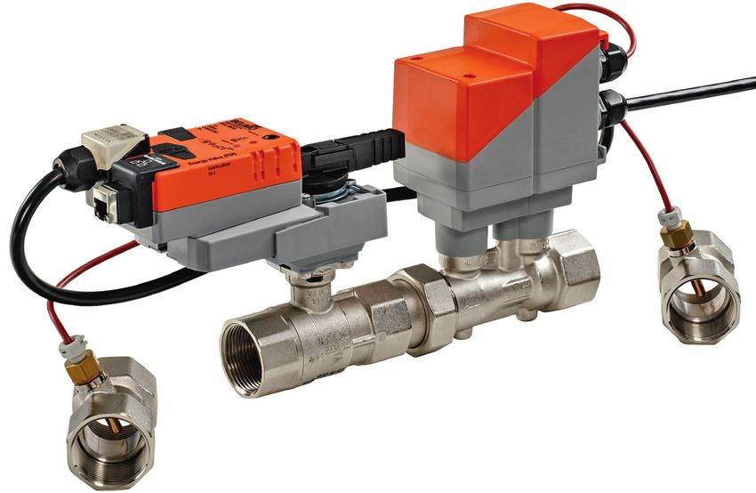
Electronic pressure-independent characterised control valve
Energy Valve with energy monitoring
Protocol Implementation Conformance Statement – PICS
General information Date 26.01.2018
Vendor Name BELIMO Automation AG
Vendor ID 423
Product Name Energy Valve
Product Model Number EV..R+(K)BAC, EV..R3+BAC, EV..F+(K)BAC
Applikations Software Version 03.02-0000
Firmware Revision 12.25
BACnet Protocol Revision 1.12
Product Description Electronic pressure-independent characterised
control valve with energy monitoring
BACnet Standard Device Profile BACnet Application Specific Controller (B-ASC)
Segmentation capability No
Data Link Layer Options MS/TP master
BACnet IP, (Annex J)
BACnet IP, (Annex J), Foreign Device
Device Address Binding No static device binding supported
Networking Options None
Character Sets Supported ISO 10646 (UTF-8)
Gateway Options None
Network Security Options Non-secure device
Conformance Listed by BTL
BACnet Interoperability Building Blocks Data sharing – ReadProperty-B (DS-RP-B)
supported BIBBs Data sharing – ReadPropertyMultiple-B (DS-RPM-B)
Data sharing – WriteProperty-B (DS-WP-B)
Data sharing – COV-B (DS-COV-B)
Device management – DynamicDeviceBinding-B (DM-DDB-B)
Device management – DynamicObjectBinding-B (DM-DOB-B)
Device management – DeviceCommunicationControl-B (DM-DCC-B)
BACnet MS/TP Baud rates 9’600, 19’200, 38’400, 76’800 (Default: 38’400)
Address 0...127 (Default: 1)
Number of nodes Max 32 (without repeater), 1 full busload
Terminating resistor 120 Ω
BACnet IP Port open (Default: 47’808)
Parameterisation Tool through the integrated webserver
All writeable objects with instance number ≥ 90 are persistent and are not supposed to be written on a
! regular base.
2 Energy Valve PICS • en-gb • 2021-04 • Subject to changes www.belimo.comElectronic pressure-independent characterised control valve
Energy Valve with energy monitoring
Protocol Implementation Conformance Statement - PICS
Standard Object Types Supported Objekt type Optional properties Writeable properties
Device Description Object Identifier
Location Object Name
Active COV Subscriptions Location
Max Master Description
Max Info Frames APDU Timeout (1’000…60’000)
Profile Name Number of APDU Retries (0...10)
Max Master (1...127)
Max Info Frames (1...255)
Analog Input [AI] Description
COV Increment
Analog Output [AO] Description Present Value
COV Increment
Analog Value [AV] Description Present Value
Binary Input [BI] Description
Active text
Inactive Text
Binary Valve [BV] Description Prresent Value
Active text
Inactive Text
Multi-state Input [MI] Description
State Text
Multi-state Output [MO] Description Present Value
State Text
Multi-state Value [MV] Description Present Value
State Text
The device does not support the services CreateObject and DeleteObject.
The specified maximum length of writable strings is based on single-byte characters and
support up to 252 characters.
Service processing The device supports the DeviceCommunicationControl and ReinitializeDevice services. No
password is required.
A maximum of 5 active COV subscriptions with a lifetime of 1…43‘200 sec. (12 hours) are
supported.
www.belimo.com Energy Valve PICS • en-gb • 2021-04 • Subject to changes 3Electronic pressure-independent characterised control valve
Energy Valve with energy monitoring
BACnet Object Description
Object Name Object Type Description Values COV Increment Access
[Instance] Comment
Status_Flags
Device Device 0…4’194’302 – W
[Inst.Nr] Default: 1
RelPos AI[1] Relative Position in % 0...100 5 R
AbsPos AI[2] Absolute Position in degree 0...90 5 R
SpAnalog_V AI[5] Analog Setpoint in Volt 0...10.00 1 R
RelFlow AI[10] Relative Flow in % 0...100 5 R
AbsFlow_lmin AI[11] Absolute Flow in l/min 0...100’000 1 R
AbsFlow_m3h AI[12] Absolute Flow in m3/h 0...600 0.1 R
AbsFlow_gpm AI[13] Absolute Flow in gpm 0...100’000 1 R
AbsFlow_ls AI[14] Absolute Flow in l/s 0...100’000 0.1 R
AbsFlow_lh AI[15] Absolute Flow in l/h 0...100’000 100 R
T1_C AI[20] Temperature 1 (remote) in C -10...+120 1 R
T2_C AI[21] Temperature 2 (embedded) in C -10...+120 1 R
DeltaT_K AI[22] Delta Temperature in K 0...130 1 R
T1_F AI[25] Temperature 1 (remote) in F 14...248 1 R
T2_F AI[26] Temperature 2 (embedded) in F 14...248 1 R
DeltaT_F AI[27] Delta Temperature in F 0...266 1 R
AbsPower_kW AI[30] Power in kW 0...2.147e+6 10 R
E_Cooling_kWh AI[31] Cooling Energy in kWh 0...2.147e+9 10 R
E_Heating_kWh AI[32] Heating Energy in kWh 0...2.147e+9 10 R
E_Cooling_MJ AI[33] Cooling Energy in MJ 0...2.147e+9 10 R
E_Heating_MJ AI[34] Heating Energy in MJ 0...2.147e+9 10 R
AbsPower_kBTUh AI[35] Power in kBTU/h 0...2.147e+6 10 R
E_Cooling_kBTU AI[36] Cooling Energy in kBTU 0...2.147e+9 10 R
E_Heating_kBTU AI[37] Heating Energy in kBTU 0...2.147e+9 10 R
RelPower AI[40] Relative Power in % 0...300 5 R
AbsPower_ton AI[45] Power in ton refrigeration 0...2.147e+6 1 R
E_Cooling_tonh AI[46] Cooling Energy in ton*h 0...2.147e+9 1 R
E_Heating_tonh AI[47] Heating Energy in ton*h 0...2.147e+9 1 R
E_CoolReset_kWh AI[50] Cooling Energy in kWh, resettable with BV[31] 0...2.147e+9 1 R
E_HeatReset_kWh AI[51] Heating Energy in kWh, resettable with BV[32] 0...2.147e+9 1 R
E_CoolReset_kBTU AI[52] Cooling Energy in kBTU, resettable with BV[31] 0...2.147e+9 1 R
E_HeatReset_kBTU AI[53] Heating Energy in kBTU, resettable with BV[32] 0...2.147e+9 1 R
GlycolConcentration AI[60] Glycol concentration in % Measured value: 0...40 1 R
Measured value or override value from webserver Override value: 0...80
ErrorState 1) AI[100] Error State Bit 0: Error Sensor T1 1 R
Error Sensor T1: Error with remote temperature sensor Bit 1: Error Sensor T2
Error Sensor T2: Error with embedded temperature sensor Bit 2: Error Flow Sensor
Error Flow Sensor: Error with the flow sensor Bit 3: Actuator cannot move
Actuator can‘t move: Mechanical overload due to blocked valve, etc. Bit 4: Flow with closed valve
Flow with closed valve: Flow is measured but position of valve is closed Bit 5: Air bubbles
Airbubbles: Air bubbles in the hydronic system Bit 6: Flow not reached
Flow not reached: Setpoint cannot be reached within 3min during flow control Bit 7: Power not realized
Power not realized: Setpoint cannot be reached within 3min during power control Bit 8: Gear disengaged
Gear disengagement active: Gear disengaged button is pressed Bit 9: Reverse flow detected
Reverse flow detected: Reverse flow is detected Bit 10: MP communication
MP communication faulty: Internal communication between sensor and actuator faulty
faulty Bit 11: Freeze warning
Freeze warning: Measured temperature & glycol concentration indicate that
grease ice can build up
SpAbsFlow_lmin AI[111] Setpoint Absolute Flow in l/min 0...100’000 1 R
SpAbsFlow_m3h AI[112] Setpoint Absolute Flow in m3/h 0...600 0.1 R
SpAbsFlow_gpm AI[113] Setpoint Absolute Flow in gpm 0...100’000 1 R
SpAbsFlow_ls AI[114] Setpoint Absolute Flow in l/s 0...100’000 0.1 R
SpAbsFlow_lh AI[115] Setpoint Absolute Flow in l/h 0...600 100 R
SpRel AO[1] Setpoint Relative in % 0...100 1 C
The set point is related either to the position, the flow (of Vmax) or the power Default: 0
(of Pmax).
See ControlMode for more information → MV[100]
Vmax_lmin AV[90] Maximum Flow Limit in l/min 30%Vnom…Vnom - W
Default: Vnom
Vmax_gpm AV [91] Maximum Flow Limit in gpm 30%Vnom…Vnom - W
Default: Vnom
Pmax_kW AV [95] Maximum Power Limit in kW 0.5%Pnom…Pnom - W
Default: Pnom
4 Energy Valve PICS • en-gb • 2021-04 • Subject to changes www.belimo.comElectronic pressure-independent characterised control valve
Energy Valve with energy monitoring
BACnet Object Description
Object Name Object Type Description Values COV Increment Access
[Instance] Comment
Status_Flags
Pmax_kBTUh AV [96] Maximum Power Limit in kBTU/h 0.5%Pnom…Pnom - W
Default: Pnom
Vmax AV [100] Maximum Flow Limit in % 30…100 - W
Default: 100
Vnom_lmin AV [101] Nominal Volume Flow in l/min Vnom - W
Vnom_gpm AV [102] Nominal Volume Flow in gpm Vnom - W
SpDeltaT_K AV [103] Setpoint DeltaT in K 1…55 - W
Default: 10
SpDeltaT_F AV [104] Setpoint DeltaT inF 2…100 - W
Default: 18
Pmax AV [105] Maximum Power Limit in % 0.5…100 - W
Default: 100
Pnom_kW AV [106] Nominal Power in kW Pnom - R
Pnom_kBTUh AV [107] Nominal Power in kBTU/h Pnom - R
SpFlow_DeltaT lmin AV [108] Setpoint Flow at DeltaT in l/min 0...Vnom - W
Default:Vnom
SpFlow_DeltaT gpm AV [109] Setpoint Flow at DeltaT in gpm 0...Vnom - W
Default:Vnom
Object Name Object Type Description Values Access
[Instance] Comment
Status_Flags
SpPosReached BI [1] Setpoint Position reached 1: No R
2: Yes
SummaryStatus BI [101] Summary Status 1: OK R
Summarizes all status from MI 103 - 107 2: Not OK
RstCoolEnergy BV [31] Reset Cooling Energy 1: None W
Sets the Cooling Energy (AI[50] / AI[52]) to zero 2: Reset
RstHeatEnergy BV [32] Reset Heating Energy 1: None W
Sets the Heating Energy (AI[51] / AI[53]) to zero 2: Reset
RstErrCount BV [100] Reset Error Counters 1: None W
2: Reset
DeltaT_ MI [102] DeltaT Manager Status 1: Not selected R
MgrStatus Not selected: dT-Manager deactivated 2: Standby
Standby: dT-Manager activated but not active 3: Active
Active: dT-Manager active 4: Scaling standby
Scaling standby: dT-Manager active with no limitation to the flow 5: Scaling active
Scaling active: dT-Manager active with limitation to the flow → AV[108]
StatusSensor MI [103] Status Sensor 1: OK R
Indicates informations within the flow sensor and both temperature sensors 2: Flow sensor not OK
3: T1 not OK
4: T2 not OK
StatusFlow MI [104] Status Flow 1: OK R
Reverse flow detected: Energy Valves detected a reverse flow 2: Reverse flow detected
Flow not reached: Setpoint cannot be reached within 3min during flow control 3: Flow not reached
Flow in closed position: Flow is measured but position of valve is closed 4: Flow in closed position
StatusMedia MI [105] Status Media 1: OK R
Airbubbles: Airbubbles in the hydronic system. As long as there are airbubbles 2: Airbubbles
in the system, position control mode is active, regardless off control mode 3: Freeze warning
setting (ControlMode MV[100]).
Freeze warning: Measured temperature & glycol concentration indicate that
grease ice can build up
StatusActuator MI [106] Status Actuator 1: OK R
Actuator cannot move: Mechanical overload due to blocked valve, etc. 2: Actuator cannot move
Gear disengaged: Gear disengaged button is pressed 3: Gear disengaged
StatusPower MI [107] Status Power 1: OK R
Power not reached: Setpoint cannot be reached within 3min during power 2: Power not reached
control
www.belimo.com Energy Valve PICS • en-gb • 2021-04 • Subject to changes 5Electronic pressure-independent characterised control valve
Energy Valve with energy monitoring
Override MO [1] Override Control 1: None C
Overrides setpoint with defined valves. It will change back to None (1) after 2: Close
2 hours. 3: Open
4: Vnom
5: Vmax
6: MotStop
7: Pnom
8: Pmax
Default: None(1)
ControlMode MV [100] Control Mode 1: Position Control W
This value defines the interpretation of the setpoint 2: Flow Control
3: Power Control
Default: Flow control(2)
DeltaT_Limitation MV [101] DeltaT Limitation 1: Disabled W
Disabled: dT-Manager not active 2: dT-Manager
dT-Manager: dT-Manager active with no restriction to flow 3: dT-Manager scaling
dT-Manager scaling: dT-Manager active with restriction of flow → AV 108] Default: Disabled(1)
SpSource MV [122] Setpoint Source 1: Analog W
If Analog(1) then actuator is controlled by analog signal 0...10 V on wire 3. 2: Bus
If Bus(2) then setpoint via bus SpRel AO[1] Default: Analog(1)
6 Energy Valve PICS • en-gb • 2021-04 • Subject to changes www.belimo.comYou can also read


