R280K KIT FOR TERMINAL UNITS (FAN COIL) - GIACOMINI SPA
←
→
Page content transcription
If your browser does not render page correctly, please read the page content below
R280K
Kit for terminal units
(fan coil) Datasheet
0960EN 07/2021
Compact preassembled kit combining the components required
for regulation, flushing and commissioning of HVAC system
terminal units (fan coils, chilled beams or ceiling air conditioning
systems) with the main distribution line.
Kit R280K includes a diverting ball valve to by-pass the terminal
unit, a full port ball valve with integrated filter, a pressure-
independent control valve (PICV), a manual air vent valve and a
drain cock.
The two ball valves enable to clean the filter and access the
terminal unit without draining the entire system.
Installation requires only 4 connections thus reducing installation
time and preventing possible errors.
Thanks to the PICV valve, the unit enables to set and maintain constant the terminal unit flow rate when the differential
pressure of the main circuit changes.
It is also possible to isolate the terminal unit and bypass the flow through the integrated ball valves.
The inlet water of the terminal unit, and therefore also through the PICV, is filtered by the filter included in the shut-off ball
valve. The drain cock drains the water when servicing and flushing the system.
Benefits
Benefits for installers Benefits for planners
• Reduction of manpower, installation time and costs on site • Prompt sizing (only two product codes)
• Quick connection (only 4 connections required) • Limitation of planning errors
• Reduced need of a preassembly area
• One single kit for both heating and cooling
• Limitation of installation errors
Giacomini S.p.A.
Via per Alzo 39, 28017 San Maurizio d’Opaglio (NO) Italia
consulenza.prodotti@giacomini.com
+39 0322 923372 - giacomini.com 1
Versions and product codes
DELIVERY-RETURN WORKING PICV WORKING
UNIT Kv PICV ACTUATOR
PRODUCT CODE CONNECTIONS CENTER DISTANCE FLOW RATE PRESSURE ∆p
IN BY-PASS (optional)
[mm] [l/h] [kPa]
40 (inlet) K281X012
R280KY003 G 1/2”F x G 1/2”F 2,4 37 - 575 16 - 400
50 (outlet) K281X022
K281EX001
R280KY004 G 3/4”F x G 3/4”F 80 3,7 64 - 1110 30 - 400 K281EX002
Accessories and spare parts
PRODUCT CODE DESCRIPTIONS AND TECHNICAL CHARACTERISTICS
Thermo-electric actuator normally closed, ON/OFF. Power 230 Vac, 50/60 Hz.
K281EX001 Power consumption 1,2 W. Working temperature range: 0÷60 °C. Opening time 4,5 minutes.
Protection class IP54. Cable length 1 m. Valve connection M30 x 1,5 mm.
Thermo-electric actuator normally closed, ON/OFF. Power 24 Vac, 50/60 Hz.
K281EX002 Power consumption 1,2 W. Working temperature range: 0÷60 °C. Opening time 4,5 minutes.
Protection class IP54. Cable length 1 m. Valve connection M30 x 1,5 mm.
Actuator 0÷10 V. Power 24 V, 50/60 Hz. Power consumption 2,5 VA.
K281X012 Working temperature range: 0÷50 °C. Opening time at max. speed 50 seconds.
Protection class IP43. Cable length 1,5 m. Valve connection M30 x 1,5 mm.
Actuator ON/OFF. Power 24 V, 50/60 Hz. Power consumption 5 VA.
K281X022 Working temperature range: 0÷50 °C. Opening time at max. speed 85 seconds.
Protection class IP40. Cable length 1,5 m. Valve connection M30 x 1,5 mm.
P206Y001 Probe holder kit (n°2) for temperature and pressure measuring.
R225EY001 Differential pressure gauge
P206AMY001 Spare cartridge for the PICV valve of R280KY003 kit (1/2”)
P206AMY002 Spare cartridge for the PICV valve of R280KY004 kit (3/4”)
R280WY003 Polyethylene insulation for R280KY003
R280WY004 Polyethylene insulation for R280KY004
Technical data
Materials
• Fluids: water, glycol-based solutions (max. 50 % of glycol) • Main components: brass CW617N - UNI EN 12165
• Working temperature range: -10÷120 °C • Ball valve gaskets: PTFE
• Room temperature: 1÷50 °C • Gaskets of other components: EPDM
• Max. working pressure: 25 bar • Filter: stainless steel AISI 304
• Max. differential pressure at the ends of the PICV valve: • Cartridge of pressure-independent control valve (PICV):
4 bar (2 bar for R280KY003) - Insert: glass-filled PSU/POM/PPS
• Actuator connection: M30 x 1,5 mm - Diaphragm: EPDM
• Filtering capacity: 500 μm - Internal metal components: stainless steel
- O-Rings: EPDM
- Stopper: PPS
Giacomini S.p.A.
Via per Alzo 39, 28017 San Maurizio d’Opaglio (NO) Italia
consulenza.prodotti@giacomini.com
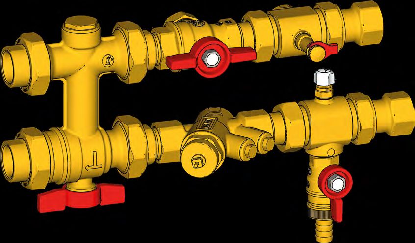
+39 0322 923372 - giacomini.com 2 Components
1 Diverting ball valve to by-pass unit
2 6
2 Ball valve with integrated filter
5 FAN COIL
3 Pressure-independent control valve (PICV)
BOILER
ROOM
4 Drain cock
5 Manual air vent valve
1 3 4
6 Probe holder
Diverting ball valve to by-pass unit (1)
Diverting ball valve carries out by-pass operations thanks to the special shaped ball that confers a compact design.
The two valves included increase the water flow to reduce losses of pressure in the terminal unit (fan coil).
Ball valve with integrated filter (2)
The valve includes a filter inside the ball to combine the functions of a filter and two shut-off valves in one single
component.
The filter can be removed by closing the valve to clean it without draining the system.
The filter has a filtering capacity of 500 μm, while the valve provides full port (DN20 for both kits) to guarantee the maximum
flow rate.
Pressure-independent control valve (PICV) (3)
The valve included guarantees high energy efficiency and state-of-the-art control. It combines the function of three valves
(DPCV, balancing and control) in one, it is easy and fast to start, saving planners time on verification calculations.
The valve can be controlled automatically, with a proportional actuator (0÷10 V) that sets the flow rate within the work range
defined by the cartridge calibration or with an ON-OFF actuator that shuts off the circuit, to perfectly adapt it to the type of
electronic setting required by the system.
Hydraulic diagram
Diverting ball valve to by-pass the unit
Ball valve with integrated filter
Probe holder (optional)
A B Pressure-independent control valve (PICV)
Manual air vent valve
Drain cock
A Boiler room
B Terminal unit (fan coil)
Giacomini S.p.A.
Via per Alzo 39, 28017 San Maurizio d’Opaglio (NO) Italia
consulenza.prodotti@giacomini.com
+39 0322 923372 - giacomini.com 3MAX
30 Nm
MAX
Installation 30 Nm
Kit R280K must be installed upstream FANofCOIL
the terminal unit
(fan coil) and includes the main components required for its
proper operation. MAX
M
BOILER ROO 30 Nm
The kit can be installed in any direction by fitting the main
components in the desired position and loosening the
MAX A nuts (ref. A); however, the following components cannot be
A 30 Nm
installed upside down:
Ball valve with PICV valve and FAN COILAir vent valve
A integrated filter its actuator
A
M
BOILER ROO
Installation with floor fan coil
FAN COIL
M
BOILER ROO
FAN COIL
M
BOILER ROO
Installation with ceiling fan coil
FAN COIL
M
BOILER ROO
FAN COIL
M
BOILER ROO
Giacomini S.p.A.
Via per Alzo 39, 28017 San Maurizio d’Opaglio (NO) Italia
consulenza.prodotti@giacomini.com
+39 0322 923372 - giacomini.com 4
A A Operation
Kit R280K enables the following operations:
1) System flushing / Maintenance
The user can fully isolate the fan coil by closing the two ball
CLOSED
valves, flush the system and carry out a chemical treatment
if desired, preventing debris from entering the fan coil and
the pressure-independent control valve (PICV).
CLOSED
This setting also enables to clean the filter integrated in the
delivery ball valve.
CLOSED
CLOSEDCLOSED
CLOSED
OPEN
CLOSED
CLOSED
2) Fan coil flushing with delivery circuit flow
OPEN CLOSED Ball valves and drain cock open.
This setting enables to flush the kit components and
CLOSED
OPEN
prevents debris from entering the pressure-independent
CLOSED control valve (PICV).
OPENOPEN
CLOSED
OPEN OPEN
OPEN OPEN
OPEN OPEN
OPEN
OPEN 3) Fan coil flushing with return circuit flow
OPEN
OPEN Ball valve on return circuit closed, ball valve on delivery
CLOSED
OPEN circuit and drain cock both open.
OPEN
OPEN
OPEN
CLOSED
OPEN
OPEN
CLOSED
CLOSED
OPEN
OPENOPEN
CLOSED
CLOSED 4) Normal operation
OPEN OPEN Ball valves open and drain cock closed.
WARNING. In normal operation, make sure the drain cock is closed with
CLOSED
the provided cap.
OPEN
CLOSED
OPEN
Giacomini S.p.A.
Via per Alzo 39, 28017 San Maurizio d’Opaglio (NO) Italia
consulenza.prodotti@giacomini.com
+39 0322 923372 - giacomini.com 5To set the valve on the desired flow
Commissioning Stem
rate, use an 8 mm wrench, turn the
8 mm
Setting of pressure-independent control valve (PICV) valve stem clockwise to decrease
Set the flow rate on the balancing valve according to the the setting and anticlockwise to
setting table. increase it.
R280KY0043 R280KY004
∆p: 16-400 kPa ∆p: 30-400 kPa
Q [l/h]
Setting l/h GPM l/h GPM Setting 5
1.0 - - 64 0,282
1.1 37 0,163 142 0,624 Setting 4
1.2 84 0,37 209 0,92 3,4 Precisione
Setting 3
1.3 116 0,51 268 1,18
1.4 151 0,664 319 1,41
Setting 2
1.5 180 0,792 366 1,61
1.6 205 0,902 408 1,8 Setting 1
1.7 234 1,03 446 1,96
1.8 259 1,14 482 2,12
Campo di lavoro
1.9 281 1,24 516 2,27 ∆p [kPa]
2.0 302 1,33 549 2,42 EXAMPLE. The figure shows a 3,4 setting.
2.1 320 1,41 580 2,56
2.2 339 1,49 611 2,69
System flushing
2.3 353 1,55 641 2,82
Before start up, the system must be flushed following the
2.4 371 1,63 671 2,95 operations described in section “Operation” (1, 2, 3).
2.5 381 1,68 700 3,08
2.6 394 1,73 728 3,21
System commissioning
2.7 406 1,79 756 3,33 Open the shut-off valves and the air vent valve completely,
2.8 414 1,82 783 3,45 then start the hydraulic system (4).
2.9 428 1,88 810 3,56 The air vent valve must be closed as soon as water comes
3.0 439 1,93 835 3,68 out instead of air.
3.1 449 1,98 860 3,79
3.2 458 2,02 883 3,89 Verification of differential pressures
3.3 468 2,06 906 3,99 The difference of differential pressure may be verified by
3.4 477 2,1 927 4,08 installing probe holders P206, the related probes and
differential pressure gauge R225E.
3.5 486 2,14 946 4,17
3.6 494 2,17 965 4,25 Verification of terminal unit differential pressure (fan coil)
3.7 503 2,21 982 4,32
3.8 511 2,25 998 4,39 P225E
3.9 518 2,28 1010 4,46
P206
4.0 526 2,31 1020 4,51
4.1 532 2,34 1040 4,57
4.2 538 2,37 1050 4,61
4.3 544 2,39 1060 4,66 R225E
4.4 549 2,42 1070 4,7
4.5 553 2,43 1080 4,73
Verification of PICV flow rate and functionality
4.6 559 2,46 1080 4,77
P225E
4.7 563 2,48 1090 4,8
4.8 567 2,5 1100 4,83 P206
4.9 571 2,51 1100 4,86
5.0 575 2,53 1110 4,89
NOTE. Accuracy: max. value between ± 10 % of controlled flow rate and ±
R225E
5 % of max. flow rate.
Giacomini S.p.A.
Via per Alzo 39, 28017 San Maurizio d’Opaglio (NO) Italia
consulenza.prodotti@giacomini.com
+39 0322 923372 - giacomini.com 6 Actuator installation and electric wiring
Actuator installation Electric wiring K281EX001, K281EX002
The PICV valve can be automized by installing two different
types of actuators; install the actuators by screwing the
gasket on the threaded connection of the valve body.
K281EX001, K281EX002
POWER SUPPLY TYPE OF
PRODUCT CODE
[V] ACTUATOR
Brown
Blue
K281EX001 230 ON/OFF
Close Open
K281EX002 24 ON/OFF
24 Vac/dc
Power 230 Vac
K281X012 24 0÷10 V
Common
K281X022 24 ON/OFF
Electric wiring K281X012 Electric wiring K281X022
BLK RED GRY
K281 24V~
1 2 3 50/60 Hz
5 VA
DOWN GREEN
COMM WHITE
UP
DOWN
UP
BROWN
AC
̃
24 V (+)
DC 0(2)...10 V
Y (+)
(-)
WIRE COLOR FUNCTION WIRE COLOR FUNCTION
Black (BLK) Contact stem “UP”
Power supply 24 V Brown (CLOSING of direct way
Red (RED) with mixing valve in progress)
White COMMON contact
Grey (GRY) Contact up/down 0-10 Vdc
Contact stem “DOWN”
Green (OPENING of direct way
with mixing valve in progress)
Giacomini S.p.A.
Via per Alzo 39, 28017 San Maurizio d’Opaglio (NO) Italia
consulenza.prodotti@giacomini.com
+39 0322 923372 - giacomini.com 7 Maintenance
We recommend inspecting the unit at least once a year when shifting from heating/cooling.
During inspection, the following components must be checked:
• Ball valve filter: rinse under running water (see “Cleaning the filter”).
• Actuator: check proper operation; the actuator should be replaced when failing with correct wiring.
• Ball valves: check proper maneuvering of ball valves.
NOTE. Also refer to local regulations for programmed maintenance operations.
Cleaning the filter
• Close the kit delivery and return ball valves
• Unscrew the octagonal cap of the ball valve with filter using a 30 mm wrench
• Remove the filter and rinse it under running water
• Reinstall the filter inside the valve making sure the filter hole (ref. ”A”) is facing the direction opposite to the flow, marked by
an arrow on the valve body (ref. “B”)
• Close the octagonal cap and open the ball valves
B
Max 10 Nm
A
Replacing the balancing valve cartridge
• Close the kit delivery and return ball valves
• Unscrew the valve cartridge with a 32 mm wrench
• Remove the cartridge and replace it with a new one
• Install the new cartridge and screw it on the valve body
• Preset the new cartridge
NEW
NEW
32 mm 32 mm
Giacomini S.p.A.
Via per Alzo 39, 28017 San Maurizio d’Opaglio (NO) Italia
consulenza.prodotti@giacomini.com
+39 0322 923372 - giacomini.com 8B C
Dimensions
R280KY003 R280KY003 R280KY003+K281
E
D
F
B C
A G H
E
D
F
A G H
R280KY004 R280KY004 R280KY004+K281
B C
B C
D
E
F
D
E
F
A G H
PRODUCT CODE CONNECTIONS A [mm] B [mm] C [mm] D [mm] E [mm] F [mm] G [mm] H [mm]
A G H
R280KY003 G 1/2”F 274 268 6 40 50 116 163 231
R280KY004 G 3/4”F 348 319 29 80 80 158 163 231
Product specifications
R280K
Connection and setting kit for terminal units of heating and cooling systems. Included: Pressure-independent control valve
(PICV), shut-off ball valves with integrated filter, diverting ball valve for by-pass, drain cock, manual air vent valve and pressure
outlet. Available in two dimensions: DN15 and DN20. System main connections 1/2”F (1/2” to 1”); terminal unit connections
1/2”F (3/4” to 1-1/4”). Connection center distance: 40/50 mm (inlet/outlet for 1/2” version), 80/80 mm (inlet/outlet for 3/4”
version). Pressure outlet connections 1/4”F (ISO 228) with cap (for dedicated versions only). Actuator connection M30 x 1,5 mm.
Setting range of unit flow rate: 37÷575 l/h (1/2”); 64÷1110 l/h (3/4”). Max. working pressure: 25 bar. Range of operation nominal
Δp 25÷400 kPa. Working temperature range -10÷120 °C. Room temperature range 1÷50 °C. Filtering capacity of filter: 500 μm.
Fluids: water and glycol-based solutions (max. 50 % of glycol). Main brass components CW617N - UNI EN 12165. Ball valve
gaskets PTFE. Gaskets of other components EPDM. AISI 304 stainless steel filter. Cartridge of pressure-independent control
valve (PICV) techno-polymer.
Safety Warning. Installation, commissioning and periodical maintenance of the product Additional information. For more information, go to giacomini.com or contact our technical
must be carried out by qualified operators in compliance with national regulations and/or local assistance service. This document provides only general indications. Giacomini S.p.A. may change
standards. A qualified installer must take all required measures, including use of Individual at any time, without notice and for technical or commercial reasons, the items included herewith.
Protection Devices, for his and others’ safety. An improper installation may damage people, The information included in this technical sheet do not exempt the user from strictly complying
animals or objects towards which Giacomini S.p.A. may not be held liable. with the rules and good practice standards in force.
Package Disposal. Carton boxes: paper recycling. Plastic bags and bubble wrap: plastic Product Disposal. Do not dispose of product as municipal waste at the end of its life cycle.
recycling. Dispose of product at a special recycling platform managed by local authorities or at retailers
providing this type of service.
Giacomini S.p.A.
Via per Alzo 39, 28017 San Maurizio d’Opaglio (NO) Italia
consulenza.prodotti@giacomini.com
+39 0322 923372 - giacomini.com 9You can also read