Thermal Design of a 100 kW Electron to Gamma Converter at TRIUMF
←
→
Page content transcription
If your browser does not render page correctly, please read the page content below

Journal of Physics: Conference Series

PAPER • OPEN ACCESS

Thermal Design of a 100 kW Electron to Gamma Converter at TRIUMF
To cite this article: B G Cade et al 2018 J. Phys.: Conf. Ser. 1067 032023

View the article online for updates and enhancements.

                                This content was downloaded from IP address 176.9.8.24 on 30/09/2020 at 05:49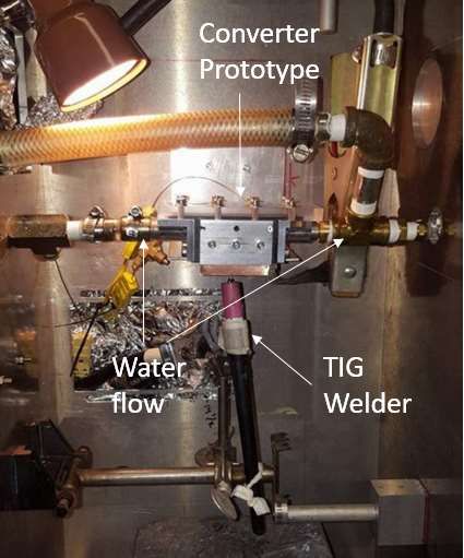
9th International Particle Accelerator Conference, IPAC18                                                       IOP Publishing
IOP Conf. Series: Journal of Physics: Conf. Series  1067 (2018)
                                               1234567890   ‘’“” 032023                   doi:10.1088/1742-6596/1067/3/032023

      THERMAL DESIGN OF A 100 KW ELECTRON TO
      GAMMA CON-VERTER AT TRIUMF

                         B G Cade1, L Egoriti1, A Gottberg1, D Priessl2
                         1
                             TRIUMF, V6T 2A3 Vancouver, Canada
                         2
                             University of Victoria, Dept. of Physics and Astronomy, V8P 5C2 Victoria, Canada

                         bcade@triumf.ca

                         Abstract. The electron target station of the TRIUMF-ARIEL Facility will employ an electron
                         "driver" beam to irradiate Isotope Separator On-Line (ISOL) targets for the production of
                         radioactive isotopes via photofission [1]. 35 MeV electrons will be converted to gamma
                         spectrum Bremsstrahlung photons via an electron to gamma (e-γ) converter located upstream
                         of the ISOL target. The e-γ concept uses a composite metal with two layers: One high-Z
                         material to stop and convert electrons to photons, and one low-Z material to provide structural
                         support, thermal dissipation, and maximal transparency to the produced gamma photons as
                         well as to provide attenuation of remaining primary electrons.. Several material combinations
                         and bonding processes are currently being evaluated and tested using TRIUMF's e-linac.
                         Water-cooling and thermal design are being optimized for 100 kW electron beam power
                         operation and have thus far been experimentally validated up to 10 kW driver beam power
                         equivalent. The latest test results and future prospects are summarized.

      1. Background
      Producing isotopes via photofission [1],[2] has the potential to improve the purity of ion beams
      available in neutron-rich regions of the chart of nuclides, which is desirable for several of the
      experiments at TRIUMF-ISAC [3]. Additionally, a photofission target station can be driven by an e-
      linac, allowing a second source of isotope production for TRIUMF’s ISAC facility independent of the
      primary 500 MeV proton cyclotron.
         The e-γ converter sits immediately upstream of the photofission target within a hermetic target
      vessel. The converter is a solid-state concept which consists of a high-Z material layer bonded to low-
      Z material layer . 35 MeV electrons strike the high-Z layer of the converter, producing gamma
      spectrum Bremsstrahlung photons that then irradiate the photofission target. Worldwide, there is little
      precedence in such systems. A similar radioisotope production mechanism is used at ALTO-IPNO [4],
      but at significantly lower electron beam power (500 W), allowing for direct irradiation of the target
      with electrons without prior conversion to X-rays. Similar converter concepts with lower electron
      energies and electron beam power were studied in [5]. The conceptual layout of the TRIUMF-ARIEL
      e-γ converter is shown in Figure 1.

      2. Thermal Design Concept
      The electron irradiation produces a very large heat load. At 100kW of beam power the converter sees
      6.0 × 10 W/m of heat flux on the High-Z surface. To dissipate this heat, the Low-Z layer is made
      of thermally conductive material (aluminum) machined into a fin array. Various fin geometries were

              Content from this work may be used under the terms of the Creative Commons Attribution 3.0 licence. Any further distribution
              of this work must maintain attribution to the author(s) and the title of the work, journal citation and DOI.
Published under licence by IOP Publishing Ltd                          1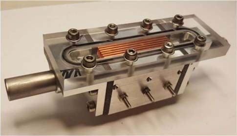
9th International Particle Accelerator Conference, IPAC18                                       IOP Publishing
IOP Conf. Series: Journal of Physics: Conf. Series  1067 (2018)
                                               1234567890   ‘’“” 032023   doi:10.1088/1742-6596/1067/3/032023

    investigated, however a simple vertical fin array was determined to be advantageous due to
    manufacturability and pressure drop requirements.

                          Figure 1. Layout of the converter and photofission target.

    2.1. Cooling Fins
    Cooling water approaches the converter perpendicularly to the beam axis, and flows over the fin arrays
    on both sides of the converter wedge.
      The fins are optimized to maintain the Low-Z material at the lowest possible temperature. ANSYS
    CFX CFD [6] software and ANSYS Design Explorer Response Surface Optimization is used to
    optimize the flow rate, fin height, fin thickness, and channel thickness to minimize temperature and
    pressure drop.
      Flow is delivered by a half-inch National Pipe Standard pipe to a diffuser shape that distributes the
    flow evenly across the converter fins. This diffuser is shown in cross-section in Figure 3 and the
    resultant flow distribution in Figure 2.

                      Figure 2. Cross-section through the horizontal plane along the beam
                      axis showing flow balance in water between all fins.

    2.2. Optimal Fin Geometry
    The selected optimized fin geometry is 4 mm tall fins, 1.2 mm thick, with 1.2 mm thick channels
    between them. At 100 kW of beam power and 50 liters per minute (L/min) of water flow the resultant
    performance is summarized in Table 1. An average effective convective heat transfer coefficient of
    58,000 W/m2K is achieved, within the range of water nucleate boiling.
      Fin efficiency is typically a desirable parameter to maximize in fin array designs, as a more efficient
    fin typically will remove more heat from the cooled body, however a low fin efficiency must be
    accepted to avoid film boiling of the water in the bottom of the fin channels.

                                                        2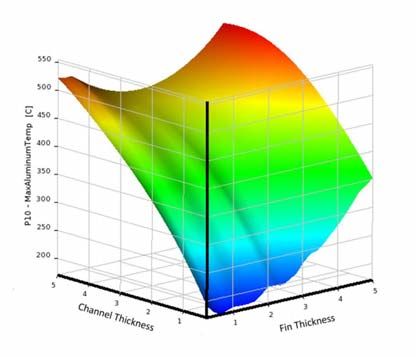
9th International Particle Accelerator Conference, IPAC18                                         IOP Publishing
IOP Conf. Series: Journal of Physics: Conf. Series  1067 (2018)
                                               1234567890   ‘’“” 032023     doi:10.1088/1742-6596/1067/3/032023

    Figure 3. Cross-section through the vertical              Figure 4. Response Surface of fin optimization
    plane along the beam axis of the converter                showing temperature as a function of fin
    weldment with diffuser shape designed to                  thickness and channel thickness.
    evenly distribute flow across all fins. Arrows
    indicate flow direction.

                                       Table 1. Optimal Fin Performance

                                                                   Value      Units

                           Effective Heat Transfer Coefficient    58,000    W/m K
                           Maximum Aluminum Temperature            350        ℃
                           Pressure Drop                             1       kPa
                           Fin Efficiency                           16        %

    2.3. ANSYS CFX Validation

    As the converter is operating within the range of possible nucleate boiling effects it is important to
    consider this in the CFD simulations. The RPI boiling model used for nucleate boiling simulation in
    ANSYS CFX is developed and validated for large surface areas such as in boilers and pressure vessels
    [7], however the very small areas present in the e-γ converter concept may introduce boiling model
    inaccuracies and therefore are validated via experiment.
      A test bench was built to replicate the power density of 10 kW electron beam power on a scaled
    down prototype converter, shown in Figure 5. A TIG welder is applied to a copper block which dif-
    fuses the heat before it reaches the aluminium converter prototype. Temperature measurements were
    taken in the body of the converter at three locations and several flow rates. This test bench is shown in
    Figure 6.

                                                          3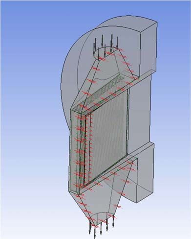
9th International Particle Accelerator Conference, IPAC18 IOP Publishing
IOP Conf. Series: Journal of Physics: Conf. Series 1067 (2018)
1234567890 ‘’“” 032023 doi:10.1088/1742-6596/1067/3/032023
Figure 5. Prototype converter in housing; converter fins Figure 6. Validation testing apparatus.
are copper surrounded by aluminum housing and a clear
polycarbonate lid. Graphite thermally isolates the
converter. Heat is applied to the bottom (not visible).
The test bench was recreated in ANSYS CFX (shown in Figure 7) and analysed with RPI boiling on
or off for each flow rate case conducted previously.
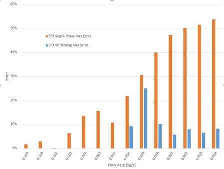
Temperature measurements were compared between the three thermocouple measurements on the
prototype and three point measurements in the ANSYS CFX model. The relative % difference between
the experimental temperature measurements and the CFX results is calculated as the flow rate is varied
and RPI boiling model is turned on or off. shown in Figure 8. CFX validation has shown that as long
as nucleate boiling is properly accounted for via the RPI model, this approach to thermal design of the
converter will have an average error less than 10%.
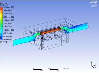
Figure 7. ANSYS CFX Converter Prototype Figure 8. Maximum % difference found between
showing flow velocity through the vertical CFX simulations and experimental validation of
mid plane. converter fins with RPI boiling model off and on.
4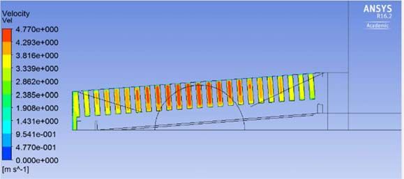
9th International Particle Accelerator Conference, IPAC18                                       IOP Publishing
IOP Conf. Series: Journal of Physics: Conf. Series  1067 (2018)
                                               1234567890   ‘’“” 032023   doi:10.1088/1742-6596/1067/3/032023

    2.4. Future Prospects
    The high flow rates deemed necessary for thermal design cause concern for the corrosion-erosion
    performance of the aluminium fins. Long term high-velocity flow tests are ongoing to examine the
    effect of sustained corrosion-erosion on the converter, which could lead to investigations of hardening
    or coating the fins.

    3. Conclusion
    Numerical thermal design, development, and benchtop validation tests of the TRIUMF-ARIEL
    electron-to-gamma converter have produced a feasible concept to withstand irradiation with 100 kW
    of 35 MeV electrons.

    4. Acknowledgements
    ARIEL is funded by the Canada Foundation for Innovation (CFI), the Provinces of AB, BC, MA, ON,
    QC, and TRIUMF. TRIUMF receives federal funding via a contribution agreement with the National
    Research Council of Canada. The authors acknowledge additional support from D. Karlen and P.
    Poffenberger (Department of Physics and Astronomy, University of Victoria).

    References
    [1] Dilling, J.,      Krücken, R. & Merminga,           L.   Hyperfine Interact, 2014,      225:   253,
              https://doi.org/10.1007/s10751-013-0906-6
    [2]    Y.T. Oganessian, S.N. Dmitriev, J. Kliman, O.A. Maslov, G.Y. Starodub, A.G. Belov, S.P.
              Tretiakova, “RIB production with photofission of uranium”, Nucl. Phys. A 701 1-4, 2002,
              87c–95c.
    [3]    A. Gottberg, “Target materials for exotic ISOL beams”, Nuclear Instruments and Methods in
              Physics Research Section B: Beam Interactions with Materials and Atoms, vol. 376, 2016,
              pp. 8-15, ISSN 0168-583X, https://doi.org/10.1016/j.nimb.2016.01.020
    [4]    Franchoo, S., Proc. Conf. Advances in Radioactive Isotope Science (ARIS2014) JPS Conf.
              Proc. 6, 020041 (2015).
    [5]    Gao, Q., Zha, H., Chen, H., & Shi, J., “Design and optimization of the target in electron linear
              accelerator”, in Proc. IPAC2013, Shanghai, China, ISBN 978-3-95450-122-9.
    [6]    ANSYS 18.2, ANSYS Inc. Southpointe, 2600 ANSYS Drive, Canonsburb, PA, 15317, USA.
    [7]    Rzehak, R., & Krepper, E., “CFD for Subcooled Flow Boiling: Parametric Variations”, in
              Science and Technology of Nuclear Installations, 2013, DOI: 10.1155/2013/687494

                                                        5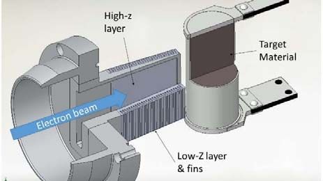
You can also read