2010 CAMARO FUEL PUMP VOLTAGE BOOSTER - Installation Instructions
←
→
Page content transcription
If your browser does not render page correctly, please read the page content below
2010 CAMARO FUEL PUMP VOLTAGE BOOSTER
   Installation Instructions

                                2010 CAMARO SS (LS3 & L99)
                                             P/N: 5A102-026

                                                                  ®

                                         ENGINEERING, LLC

                  1650 Pacific Avenue, Channel Islands, CA 93033-9901 • Phone 805 247-0226
               Fax: 805 247-0669 • www.vortechsuperchargers.com • M-F 8:00 AM - 4:30 PM (PST)

DP/N: 007124                                                                                    02/08/10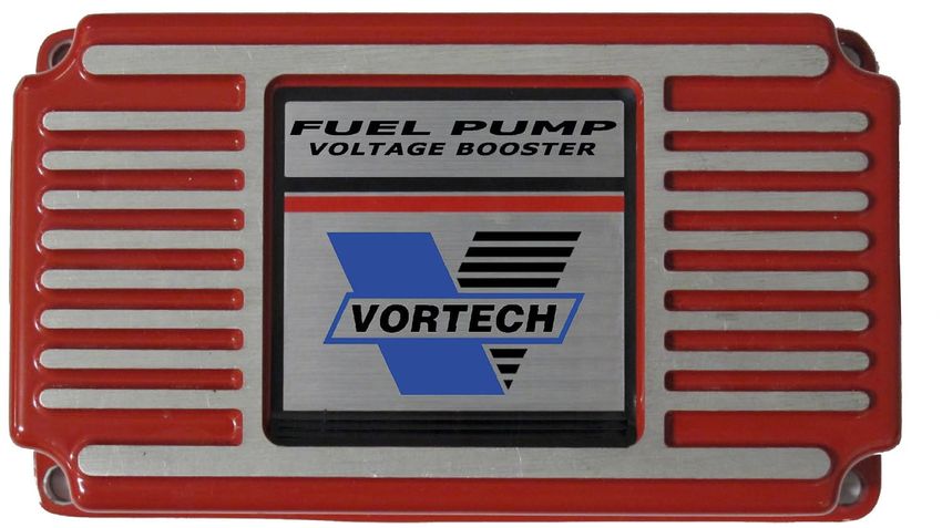
FOREWORD

                   This manual provides information on the installation, maintenance and service of the
                   Vortech supercharger kit expressly designed for this vehicle. All information, illustrations
                   and specifications contained herein are based on the latest product information available at
                   the time of this publication. Changes to the manual may be made at any time without
                   notice. Contact Vortech Engineering for any additional information regarding this kit and
                   any of these modifications at (805) 247-0226 8:00am-4:30pm PST.

                                            Take note of the following before proceeding:
                                            1.    Proper installation of this supercharger kit requires general automo-
                                            tive mechanic knowledge and experience. Please browse through each
                       STOP                 step of this instruction manual prior to beginning the installation to deter-
                                            mine if you should refer the job to a professional installer/technician.
                                            Please contact your dealer or Vortech Engineering for possible installers
                                            in your area.
                       2.       This product was designed for use on stock (un-modified, OEM)
                                vehicles. The PCM (computer), engine, transmission, drive axle
                                ratios and tire O.D. must be stock. If the vehicle or engine has been modi-
                                fied in any way, check with Vortech prior to installation and use of this product.
                       3.       Use only premium grade fuel with a minimum of 91 octane (R+M/2).
                       4.       Always listen for any sign of detonatlion (knocking/pinging) and discontinue hard
                                use (no boost) until the problem is resolved.
                       5.       Vortech is not responsible for any clutch, transmission, drive-line or engine dam-
                                age.
                                Exclusions from Vortech warranty coverage considerations
                                include, but not limited to:
                       1.       Neglect, abuse, lack of maintenance, abnormal operation or improper installation.
                       2.       Continued operation with an impaired vehicle or sub-system.
                       3.       The combined use of Vortech components with other modifications such as, but
                                not limited to, exhaust headers, aftermarket camshafts, nitrous oxide, third party
                                PCM programming or other such changes.

                                            ©2010 VORTECH ENGINEERING, LLC
       All rights reserved. No part of this publication may be reproduced, transmitted, transcribed, or translated into
           another language in any form, by any means without written permission of Vortech Engineering, LLC.

DP/N: 007124v1.0
© 2010 Vortech Engineering, LLC
All Rights Reserved, Intl. Copr. Secured.
08FEB2010 FPVB UPGRADE                                                      ii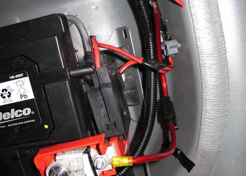
TABLE OF CONTENTS

FORWORD  . . . . . . . . . . . . . . . . . . . . . . . . . . . . . . . . . . . . . . . . . . . . . . . . . . . . . . . . . . . . . . . ii
TABLE OF CONTENTS . . . . . . . . . . . . . . . . . . . . . . . . . . . . . . . . . . . . . . . . . . . . . . . . . . . . iii
TOOL & SUPPLY REQUIREMENTS  . . . . . . . . . . . . . . . . . . . . . . . . . . . . . . . . . . . . . . . . iv
PARTS LIST  . . . . . . . . . . . . . . . . . . . . . . . . . . . . . . . . . . . . . . . . . . . . . . . . . . . . . . . . . . . . . v
1.      PREPARATION AND REMOVAL . . . . . . . . . . . . . . . . . . . . . . . . . . . . . . . . . . . . . . . . . . . 1
2.      FUEL PUMP VOLTAGE BOOSTER MOUNTING  . . . . . . . . . . . . . . . . . . . . . . . . . . . . . . 7
3.      FUEL PUMP VOLTAGE BOOSTER WIRING  . . . . . . . . . . . . . . . . . . . . . . . . . . . . . . . . . 8
4.      FINAL ASSEMBLY . . . . . . . . . . . . . . . . . . . . . . . . . . . . . . . . . . . . . . . . . . . . . . . . . . . . . . 12
5.      FINAL CHECK . . . . . . . . . . . . . . . . . . . . . . . . . . . . . . . . . . . . . . . . . . . . . . . . . . . . . . . . . 13

                                                                                                                                      DP/N: 007124v1.0
                                                                                                                       © 2010 Vortech Engineering, LLC
                                                                                                                All Rights Reserved, Intl. Copr. Secured.
                                                                         iii                                               08FEB2010 FPVB UPGRADE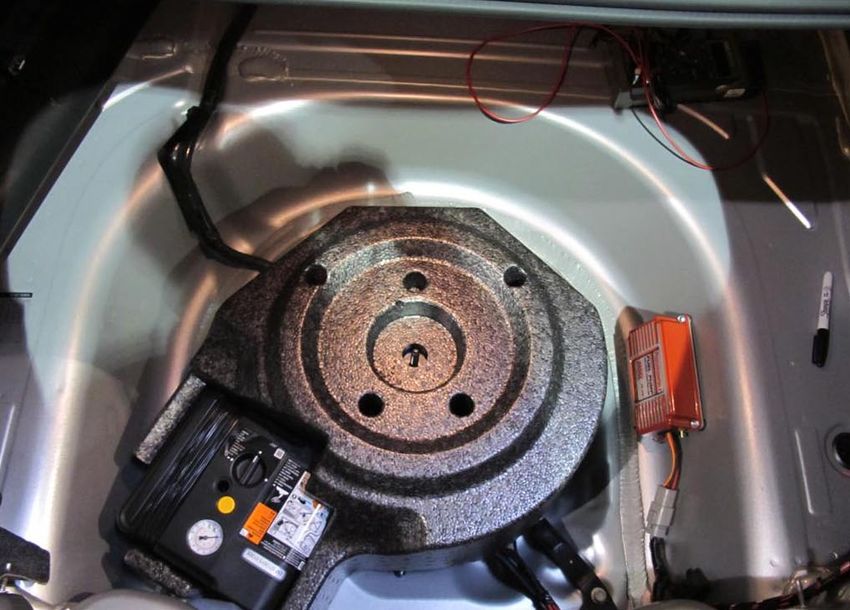
Vortech FUEL PUMP VOLTAGE BOOSTER
                                                 Installation Instructions
                                            2010 CHEVROLET CAMARO SS

                                         Before beginning this installation,
                                 please read through this entire instruction booklet

                      The Vortech 2010 Camaro Fuel Pump Voltage Booster (FPVB) upgrade was designed
                      specifically for use on 2010 Chevrolet Camaro SS vehicles equipped with a supercharg-
                      er to support applications with increased horsepower over the basic kit. As with any
                      power enhancing product, this unit is intended for use on healthy, well-maintained
                      engines. Vortech Engineering is not responsible for engine damage. Installation on new
                      vehicles will not harm or adversely affect the break-in period so long as factory break-in
                      procedures are followed.
                      For best performance and continued durability, please take a note of the following key
                      points:
                          1.        Use only premium grade fuel 91 octane or higher (R+M/2).
                          2.        Always listen for any sign of detonation (pinging) and discontinue hard use (no
                                    boost) until problem is resolved.

     TOOL & SUPPLY REQUIREMENTS:
             •     Open End Wrenches (5/16”, 10mm)
             •     3/8” Ratchet
             •     10mm, 13mm, and 5/16” Sockets
             •     Flat #2 Screwdriver
             •     Phillips #2 Screwdriver
             •     Utility Knife
             •     Heat Gun
             •     Soldering Iron/Gun
             •     Electrical Tape
             •     Wire Cutters, Strippers and Crimpers
             •     Drill Motor
             •     1/8”, Drill Bit
             •     Tape Measure

DP/N: 007124v1.0
© 2010 Vortech Engineering, LLC
All Rights Reserved, Intl. Copr. Secured.
08FEB2010 FPVB UPGRADE                                                  iv
                                                                         iv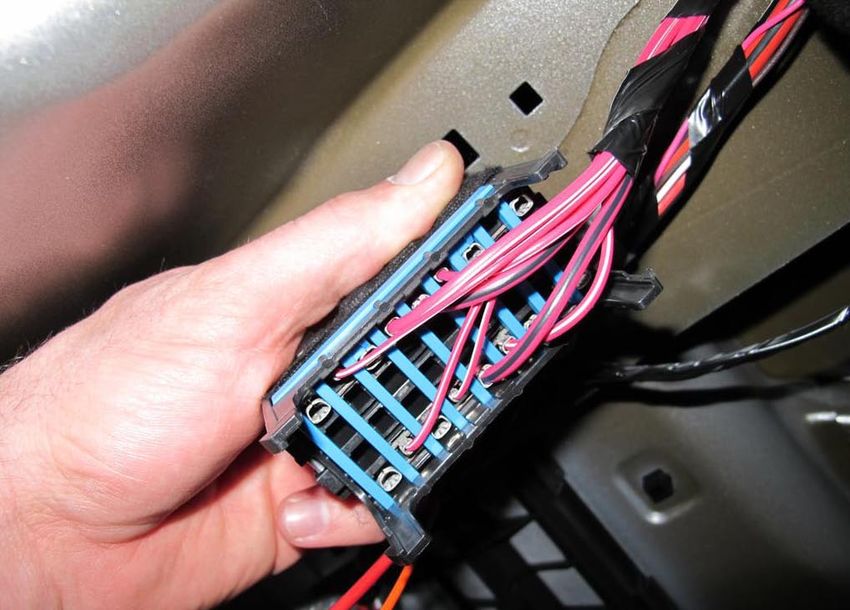
2010 CAMARO SS FUEL PUMP
VOLTAGE BOOSTER UPGRADE
2010 CHEVROLET CAMARO SS                                          Part No. 5A102-026

PARTS LIST
   IMPORTANT: Before beginning installation, verify that all parts are included in the kit.
              Report any shortages or damaged parts immediately.

PART NO.             DESCRIPTION              QTY
5a102-026	ASSY, VOLT BOOST 2010 CAMARO
  5A002-026  VOLTAGE BOOSTER, 2010 CAMARO        1
  5W001-011    16-14 GA RING TERM .26" HOLE      1
  5W001-032       1/4" PLASTIC WIRE LOOM      70 IN
  5W001-007      3/16" HEAT-SHRINK TUBING     0.4 FT
  7E010-049  #10X3/4 HEX HD SLF DRL SHT MTL      4
  7U100-044          TIE WRAP, 4" NYLON         10
  7U100-055         TIE WRAP, 7.5" NYLON        10
  5W001-037   12-10 GA BUTT CON, SHRNK TYPE      2
  5W001-078        FUSE, BLADE TYPE 40 A         1
  5W001-014         FUSE HOLDER 10 GA            1
  5W001-043    12-10GA x 1/4" RING TERMINAL      1
  007124    INSTR, 2010 CAMARO FPVB UPGRAD       1

                                                                                            DP/N: 007124v1.0
                                                                             © 2010 Vortech Engineering, LLC
                                                                      All Rights Reserved, Intl. Copr. Secured.
                                                       v                         08FEB2010 FPVB UPGRADE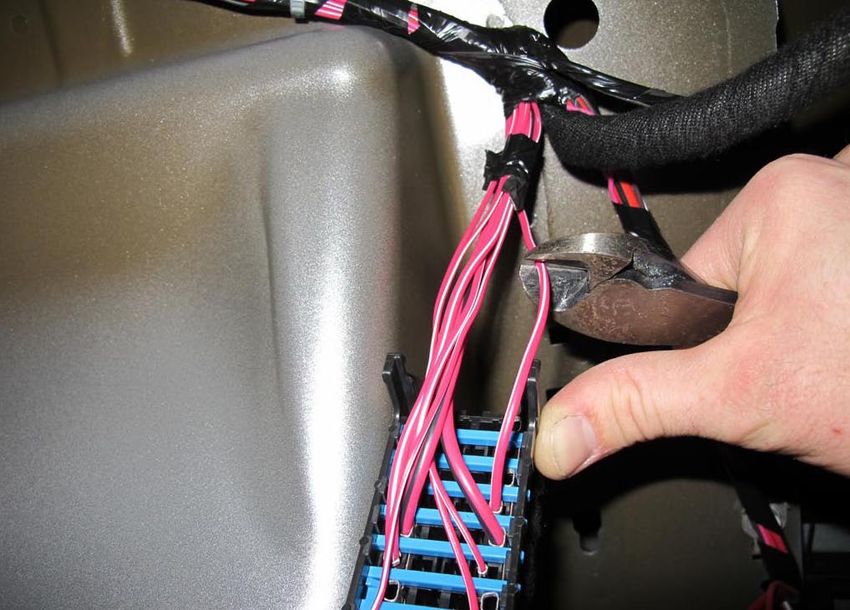
This page intentionally left blank

DP/N: 007124v1.0
© 2010 Vortech Engineering, LLC
All Rights Reserved, Intl. Copr. Secured.
08FEB2010 FPVB UPGRADE                                         vi
1.        PREPARATION AND REMOVAL
     A.   Open the trunk
     B.   Remove the carpet
     C.   Turn the center retainer counterclockwise to
          remove the trunk compartment cover

                                                             Fig. 1-a

                                                             Fig. 1-b

                                                             Fig. 1-c

                                                                                    DP/N: 007124v1.0
                                                                     © 2010 Vortech Engineering, LLC
                                                              All Rights Reserved, Intl. Copr. Secured.
                                                         1               08FEB2010 FPVB UPGRADE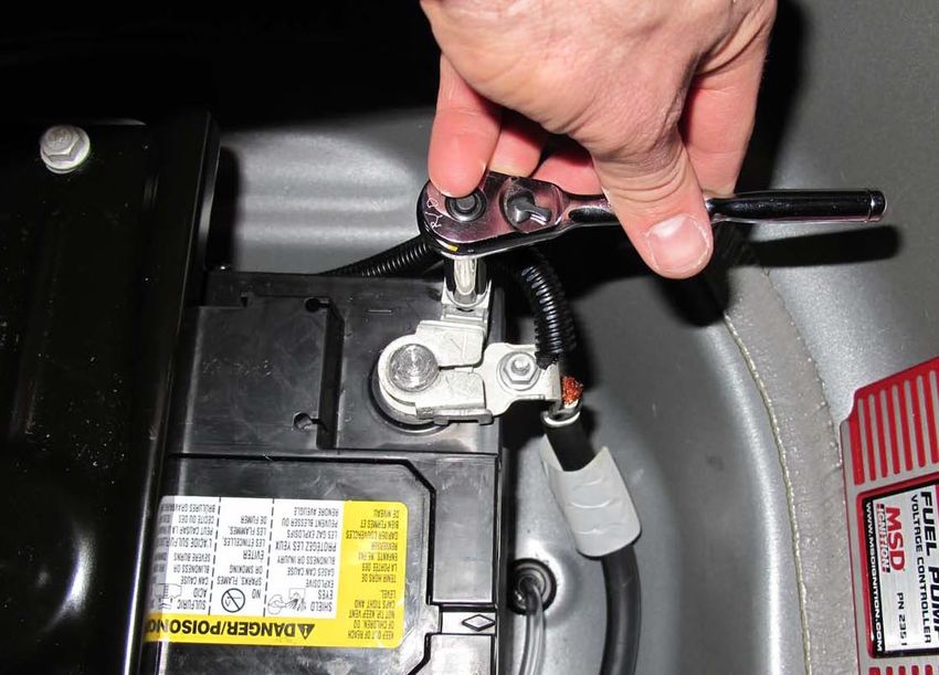
1.         PREPARATION AND REMOVAL, cont’d
          D.       Remove the tire sealant and compressor kit or
                   spare tire from trunk
          E.       Using a 10mm socket or wrench, remove the neg-
                   ative terminal from the battery.

                                                                       Fig. 1-d

                                                                       Fig. 1-e

                                                                       Fig. 1-f

DP/N: 007124v1.0
© 2010 Vortech Engineering, LLC
All Rights Reserved, Intl. Copr. Secured.
08FEB2010 FPVB UPGRADE                                             2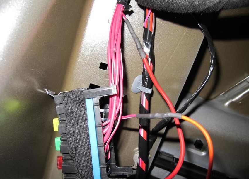
1.        PREPARATION AND REMOVAL, cont’d
     F.   Remove the six plastic nuts (three on each side)
          holding the rear plastic panel of the trunk
     G.   Remove the rear panel by first pulling up slightly
          and then out in order to release the two spring
          clips underneath.

                                                               THREE PER
                                                                  SIDE

                                                                           Fig. 1-g

                                                                           Fig. 1-h

                                                                                               PULL UP
                                                                                             SLIGHTLY TO
                                                                                              SEPARATE
                                                                                                HERE

                                                                           Fig. 1-i

                                                                                                  DP/N: 007124v1.0
                                                                                   © 2010 Vortech Engineering, LLC
                                                                            All Rights Reserved, Intl. Copr. Secured.
                                                           3                           08FEB2010 FPVB UPGRADE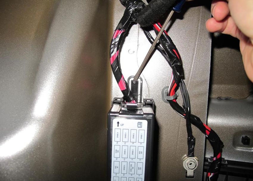
1.          PREPARATION AND REMOVAL, cont’d
          H.       Remove the two plastic fasteners holding the car-
                   pet lining to the right side of the trunk. Peel back
                   the carpet lining so that you can access the fuse
                   block mounted on the wall

                                                                           REMOVE
                                                                          FASTENERS

                                                                                Fig. 1-j

                                                                                Fig. 1-k

DP/N: 007124v1.0
© 2010 Vortech Engineering, LLC
All Rights Reserved, Intl. Copr. Secured.
08FEB2010 FPVB UPGRADE                                               4
1. PREPARATION AND REMOVAL, cont’d
I. Dismount the fuse block from the trunk wall by
unlatching the tab at the top with a screwdriver
and then sliding the entire terminal block up until it
can be pulled straight out.
Fig. 1-l
Fig. 1-m
Fig. 1-n
DP/N: 007124v1.0
© 2010 Vortech Engineering, LLC
All Rights Reserved, Intl. Copr. Secured.
5 08FEB2010 FPVB UPGRADE1. PREPARATION AND REMOVAL, cont’d
J. Remove and separate the rear cover from the
back of the fuse block by releasing the latches at
each corner.
Fig. 1-o
Fig. 1-p
Fig. 1-q
DP/N: 007124v1.0
© 2010 Vortech Engineering, LLC
All Rights Reserved, Intl. Copr. Secured.
08FEB2010 FPVB UPGRADE 62. FUEL PUMP VOLTAGE BOOSTER MOUNTING
A. Position the mounting box into the approximate
location shown and mark the four mounting cor-
ners for drilling
B. Drill the four mounting holes with a 1/8” drill
C. Mount the FPVB unit using the supplied #10 sheet
DRILL WITH
metal screws. 1/8" DRILL
Fig. 2-a
Fig. 2-b
DP/N: 007124v1.0
© 2010 Vortech Engineering, LLC
All Rights Reserved, Intl. Copr. Secured.
7 08FEB2010 FPVB UPGRADE3. FUEL PUMP VOLTAGE BOOSTER WIRING
A. Locate the red with white stripe wire, fourth row
down from the top on the right side when viewing
the fuse block from the back.
B. Cut the wire approximately two inches from the
back of the fuse block as shown.
C. Strip both ends of the cut wire.
D. Locate the wire harness supplied with the Fuel
Pump Booster (FPVB)
E. Temporarily plug the FPVB harness into the con-
nector on the FPVB unit. Route the orange signal
wire and red “PUMP +” wire along side the OEM RED/WHITE
WIRE TO CUT
wiring so that it meets up with the OEM fuse block
location. Cover the wires with the supplied split-
Fig. 3-a
loom and secure with zip ties. Unplug the FPVB
harness from the FPVB unit.
F. Trim the red and orange FPVB wires to the proper
length, as they will be soldered into the previously
cut red with white stripe OEM wires.
APPROX.
2 INCHES
Fig. 3-b
Fig. 3-c
DP/N: 007124v1.0
© 2010 Vortech Engineering, LLC
All Rights Reserved, Intl. Copr. Secured.
08FEB2010 FPVB UPGRADE 83. FPVB WIRING , cont’d
G. Cut two 1” pieces of supplied heat shrink sleeve
and slide one each over the red “PUMP+” and
orange wires.
H. Solder the orange wire to the red with white stripe
wire, previously cut, leading back to the fuse block
I. Solder the red “PUMP+” wire to the red with white
stripe wire, previously cut, leading into the cars
wiring harness.
J. Pull the heat shrink sleeve over the two soldered
connections and properly shrink with heat gun to
protect the connections.
K. Reattach the rear cover to the back of the fuse
block.
Fig. 3-d
Fig. 3-f Fig. 3-e
FUSE HOLDER RED “PUMP +”
W/ 40 A FUSE
SOLDER
CONNECTIONS
ORANGE
OEM WIRE
(RED/WHITE STRIPE)
BATTERY FPVB
SOLDER
FUSE
CONNECTION BLOCK
BLACK “BATT -”
RED “BATT +”
Fig. 3-g
DP/N: 007124v1.0
© 2010 Vortech Engineering, LLC
All Rights Reserved, Intl. Copr. Secured.
9 08FEB2010 FPVB UPGRADE3. FPVB WIRING , cont’d
L. Remount the fuse block to the trunk wall and
snap in place.
M. Reinstall the cover onto the fuse block.
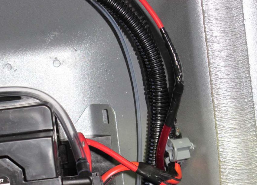
N. Using the remaining split loom and zip ties, route
the black "BATT-" and red “BATT+” wires from
the harness plug to each of the respective bat-
tery terminals. (Red to battery positive and Black
to battery negative/ground)
O. Trim and strip the black "BATT -" wire to length
and crimp on a blue supplied ring terminal.
P. Using a 10mm socket or wrench, attach the ring
terminal to the factory battery terminal as shown.
Fig. 3-h
NOTE: Do NOT reattach to battery at this time.
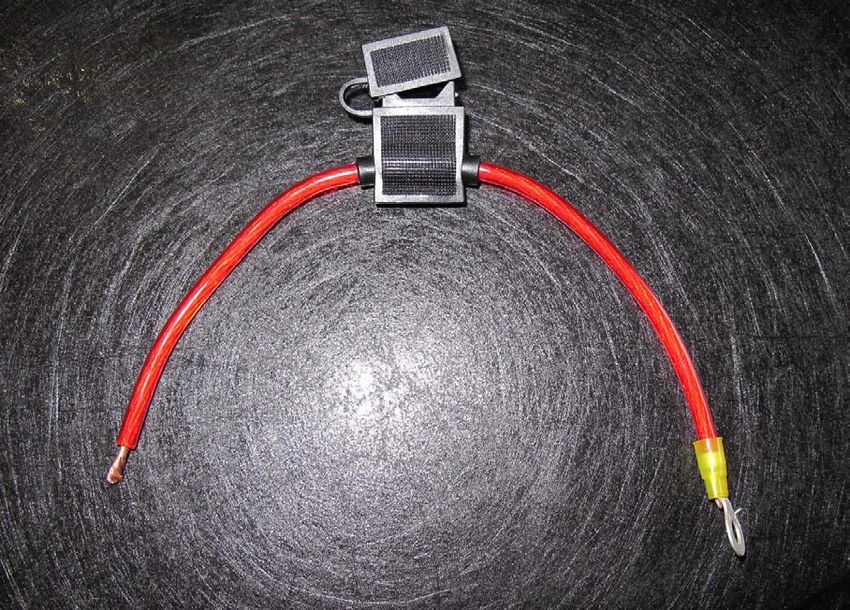
Q. Locate the supplied fuse holder. Cut and strip
both ends of the wire at the middle.
R. On one end of the fuse holder, crimp on the sup-
plied yellow ring terminal.
S. With fuse NOT installed in fuse holder, attach the
yellow ring terminal to the positive factory battery
terminal, using a 10mm socket or wrench.
ATTACH BLUE
RING TERMINAL
HERE
Fig. 3-i
ATTACH
YELLOW RING
TERMINAL HERE
Fig. 3-k Fig. 3-j
DP/N: 007124v1.0
© 2010 Vortech Engineering, LLC
All Rights Reserved, Intl. Copr. Secured.
08FEB2010 FPVB UPGRADE 103. FPVB WIRING , cont’d
T. Trim and strip the red "BATT +" wire to length to
mate up with the other end of the fuse holder.
U. Cut a 1" piece of the supplied heat shrink and SOLDER,
slide over the end of the red "BATT +" wire HEAT SHRINK,
AND TAPE
V. Solder the end of the red "BATT +" wire to the
fuse holder wire.
W. Pull the heat shrink sleeve over the soldered
connection and properly shrink with heat gun to
protect the connection. Tape with electrical tape
to ensure a sealed connection.
X. Cover wires with supplied split loom and secure
with zip ties.
Y. Trim positive battery terminal cover as necessary Fig. 3-l
for the lid to shut securely.
Z. Install 40A fuse into fuse holder and close fuse
holder cover.
Fig. 3-m
Fig. 3-o Fig. 3-n
DP/N: 007124v1.0
© 2010 Vortech Engineering, LLC
All Rights Reserved, Intl. Copr. Secured.
11 08FEB2010 FPVB UPGRADE4. FINAL ASSEMBLY
A. Connect the plug from the FPVB unit to the plug
of the installed harness.
B. Using a 10mm socket or wrench, reattach the
negative OEM terminal to the battery.
C. Replace the remaining car trim items in the
reverse order in which they were removed.
Fig. 4-a
Fig. 4-b
Fig. 4-c
DP/N: 007124v1.0
© 2010 Vortech Engineering, LLC
All Rights Reserved, Intl. Copr. Secured.
08FEB2010 FPVB UPGRADE 125. FINAL CHECK
WARNING: Do not attempt to operate the vehicle
until ALL components are installed and ALL
operations are completed including the final
check.
A. Confirm that all connections are properly insulated
and secure from creating any shorts. Make sure
all wires are properly secure with clamps or tie-
wraps.
B. Make sure all wires are routed away from hot,
moving or sharp objects.
C. Test drive the vehicle.
D. Always listen carefully for engine detonation.
Discontinue heavy throttle usage if detonation is
heard.
DP/N: 007124v1.0
© 2010 Vortech Engineering, LLC
All Rights Reserved, Intl. Copr. Secured.
13 08FEB2010 FPVB UPGRADE®
ENGINEERING, LLC
1650 Pacific Avenue, Channel Islands, CA 93033-9901 • Phone 805 247-0226
Fax: 805 247-0669 • www.vortechsuperchargers.com • M-F 8:00 AM - 4:30 PM (PST)
DP/N: 007124 02/08/10You can also read