M.B.T. Revision Tray
SURGICAL TECHNIQUE
←
→
Page content transcription
If your browser does not render page correctly, please read the page content below
M.B.T. Revision Tray SURGICAL TECHNIQUE
Contents

M.B.T. Revision Knee Surgery – Introduction           1

Surgical Technique                                    3

Intraoperative Evaluation                             5

Initial Preparation of the Tibia                      7

Preparation of the Metaphyseal Bone–Tapered Reamer    9

Proximal Tibial Resection–Tapered Reamer             10

Preparation of the Metaphyseal Bone–Broach           11

Final Preparation of the Tibia                       12

Assembling the Prosthesis                            13

Bone Cement                                          15

Trial Reduction                                      16

Appendix I: The Cemented Tibial Stem Extensions      18

Appendix II: Step Wedge Preparation                  21

Appendix III: Thick Tray Preparation                 24
M.B.T. Revision Knee Surgery
Introduction Preoperative Planning
In total knee arthroplasty, failure may result from Revision total knee arthroplasty begins with
wear, aseptic loosening, infection, osteolysis, thorough clinical and X-ray evaluation. Physical
ligamentous instability, arthrofibrosis or evaluation includes examination of soft tissues,
patellofemoral complications. In approaching previous skin incisions, range of motion, motor
revision procedures, the surgeon must consider strength, condition of all neurovascular structures,
the incision in a previously operated site, the ligamentous stability and the integrity of the
condition of the soft tissue, mobilization of the extensor mechanism.
extensor mechanism, extraction of the primary
prosthesis and the conservation of bone stock. Obtain biplanar radiographic and tangential views
Among the goals of revision arthroplasty are the of the patella and full-length standing bilateral
restoration of anatomical alignment and functional extremity views to assess alignment and bone stock,
stability, fixation of the revision implants and documentation of the joint line and evaluation of
accurate re-establishment of the joint line. Careful the present implant fixation. Stress views are
selection of the appropriate prosthesis is important. helpful in evaluating ligamentous instability. CAT
Ideally, the revision knee replacement system will and MRI scans may be of value in cases of massive
offer the options of adjunctive stem fixation, bone loss or substantial anatomic distortion from
methods to manage bone loss and various levels trauma and metabolic bone disorders. Templates are
of prosthetic constraint. used to establish replacement implant size and the
alignment of bone cuts, as well as plan for augments
or metaphyseal filling sleeves that might be needed
to manage bone loss and restore the joint line.
1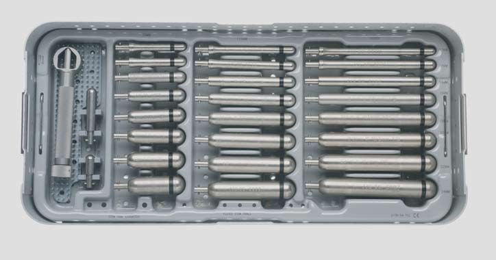
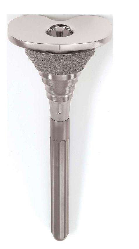
The M.B.T. Revision Knee System                             • 30, 60 and 90 mm Cemented Tibial
Is Comprised of the Following                                 Stem lengths in 13 mm diameter

Components:                                                 • Accepts rotating platform inserts from LCS®
                                                              Complete™, P.F.C.® Sigma™ RP, LCS Complete
• 8 sizes of tibial components available
                                                              Revision and Sigma TC3 RP inserts
• Five sizes of stepped metaphyseal filling and
                                                            • Accepts rotating platform hinged insert from
  loading sleeves
                                                              the Orthogenesis LPS™ (Limb Preservation
• Tibial Wedge Augmentation Components:                       System), which is compatible with the S-ROM®
  Step Wedge in 5, 10 and 15 mm thicknesses                   Noiles™ Rotating Hinge (NRH) femoral
                                                              component and LPS femoral component
• 75, 115 and 150 mm Fluted Tibial Stem lengths
  in 10 to 24 mm diameters in 2 mm increments

         Type 1                                     Type 2                                   Type 3
    T1 Tibia/F1 Femur                          T2 Tibia/F2 Femur                        T3 Tibia/F3 Femur

• Localized defect: cortical 		 • Cortical rim intact                               • Loss of entire metaphysis
  rim intact                    • Central or peripheral metaphysis loss               and cortex
• Near normal joint line        • Requires cement fill, cancellous bone graft, 		   • Requires structual bone
• Often requires small 		     augments or sleeves to restore joint line.              graft, hinged implant, sleeve
  amounts of bone graft                                                               or custom component
                                                                                    • Compromised ligaments

                                                                                                                2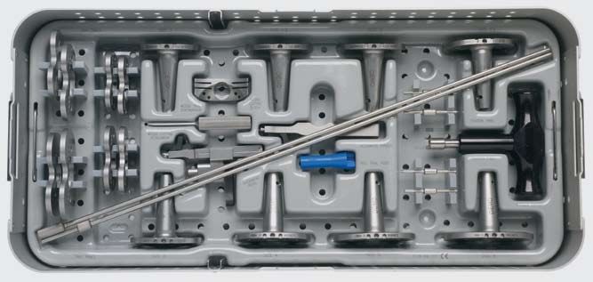
Surgical Technique

Initial Incision

Where possible, follow the scar from the primary
procedure. [Fig. 1] Where parallel incisions are
present, use the most lateral incision, as the blood
supply to the extensor surface is medially dominant.
Where a transverse patellectomy scar is present,
transect the incision at 90 degrees. Where there
are multiple incision scars or substantial cutaneous
damage (burn cases, skin grafting, etc.), consider
consulting a plastic surgeon prior to surgery to
design the incision, determine the efficacy of
preoperative soft tissue expansion and plan for
appropriate soft tissue coverage at closure.

                                                       Fig. 1

3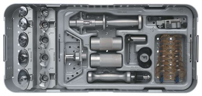
Capsular Incision

Extend the fascial incision from the proximal
margin of the rectus femoris to the distal margin
of the tibial tubercle following the medial border
of the patella. Maintain a 1⁄8 in. (3.2 mm) cuff for
reapproximation of the vastus medialis aponeurosis
at closure. [Fig. 2] Where mobilization of the exten-
sor mechanism and patella is problematic, extend
the skin and capsular incisions proximally.

                                                         Fig. 2

                                              Fig. 3

                                                        Sublux patella into lateral gutter. Occasionally, an
                                                        early lateral retinacular release is indicated to assist
                                                        patellar eversion. Where eversion difficulties persist,
                                                        a quadriceps snip, a proximal inverted quadriceps
                                                            incision (modified V-Y) or a tibial tubercle
                                                            osteotomy may be indicated. Perform the
                                                            appropriate ligamentous release based on
                                                        preoperative and intraoperative evaluation. Release
                                                        fibrous adhesions to re-establish the suprapatellar
                                                        pouch and medial and lateral gutters. To subluxate
                                                        or dislocate the tibia forward and into external
                                                        rotation, release the tissues attached to the proximal
                                                        medial tibia. [Fig. 3]

                                                        In many revision cases, the posterior cruciate
                                                        ligament will be absent or nonfunctional; excise
                                                        any residual portion.

                                                                                                              4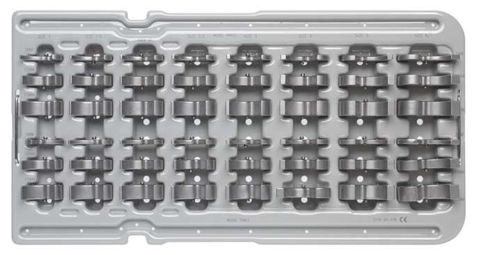
Intraoperative Evaluation
                                                                                                     Fig. 4
Establish two anatomic conditions to facilitate revision
arthroplasty: the level of the joint line and the disparity in the
flexion and extension gaps.

Joint Line Evaluation
An average knee in full extension will approximate the
true joint line by referencing several landmarks [Fig. 4]:
                                                                                                                A      B
(A) 12 to 16 mm distal to the femoral PCL attachment
(B) Approximately 3 cm distal to the medial epicondyle               C

    and 2.5 cm distal to the lateral epicondyle
(C) Distal to the inferior pole of the patella 		                    D
    (approximately one finger width)
(D) Level with the old meniscal scar, if available

Additional preoperative joint line assessment tools
include:
1. Review of original preoperative X-ray of the total knee
   arthroplasty (TKA)
2. Review of X-ray of contralateral knee if not implanted
   to determine correct size of femoral implant and
   subsequently the proper joint line in flexion

                                                             Extraction of Implants from the
                                    Fig. 5
                                                             Primary Procedure
                                                             Preserve as much bone as possible. Assemble a
                                                             selection of tools, including thin osteotomes, an
                                                             oscillating or microsagital saw, a high-speed burr
                                                             and various extraction devices.

                                                             Carefully disrupt the bone/cement or bone/prosthesis
                                                             interface before extraction is attempted. Disengage
                                                             and extract the implanted components as gently as
                                                             possible to avoid fracture and unnecessary sacrifice of
                                                             bone stock. To replace the entire prosthesis remove
                                                             the femoral component first, as this will enhance
                                                             access to the tibia. Clear all residual methyl
                                                             methacrylate with chisels or power tools. [Fig. 5]

5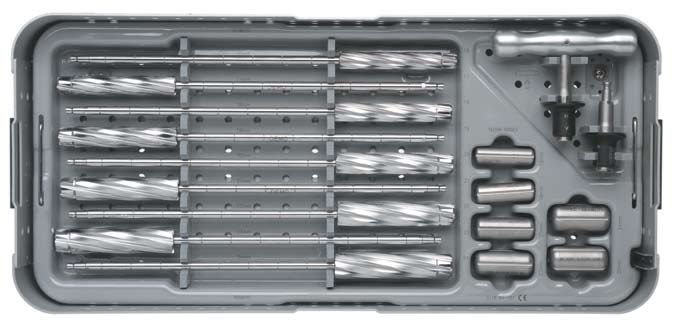
Joint Space Assessment                                      When the joint line is elevated, the preferred
                                                            correction is posterior and distal femoral
Evaluate the joint space with spacer blocks to              augmentation with a larger femoral component.
determine the flexion/extension gap relationship            The alternative—additional distal femoral resection
and the symmetry of both the flexion and                    and use of a thicker tibial insert to tighten the flexion
extension gaps [Figs. 6 and 7], and to indicate             gap—is not recommended as considerable bone
if prosthetic augmentation is needed to ensure              stock has been sacrificed in the primary procedure. It
postoperative balance.                                      is important to avoid additional resection of the dis-
                                                            tal femur, except where the joint line is not elevated
Size the tibia first, then size the femoral component       and minimal distal resection will increase the exten-
(selecting the same size femoral component). This           sion gap toward equivalency with the flexion gap.
can be adjusted to accommodate the following
situations:                                                 extension gap        >flexion gap:

flexion gap      >extension gap:                            To decrease the extension gap without affecting
                                                            flexion gap, augment the distal femur with bone
To decrease the flexion gap without affecting               graft or prosthetic augmentation.
extension gap, use a larger femoral component.
This is particularly important where an I.M. stem           Note: This will lower the joint line and lessen the
                       extension is indicated, as the       incidence of postoperative patella infera which is
                       stem extension will determine        usually desirable. The joint line is generally found to be
                        the anteroposterior positioning     elevated in revision cases. This will lessen the incidence
                          of the component and the          of postoperative patellar infera.
                            subsequent flexion gap.*

                                        *If a lateral X-ray of the
                                        preoperative knee is
                                        available, templating the
                                        appropriate size will be
                                        very helpful in choosing
                                        the appropriate femoral
                                        implant size.

                              Fig. 6                                                               Fig. 7

                                                                                                                     6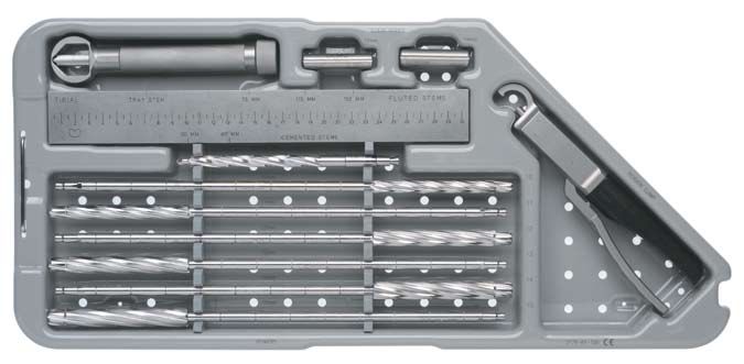
Initial Preparation of the Tibia

The Tibial Alignment System                            Place the knee in maximal flexion with the patella
                                                       laterally everted and the tibia distracted anteriorly and
When preoperative evaluation and X-rays indicate       stabilized. Release fibrosis around the tibial border
that fluted stem extensions, metaphyseal sleeves or    or excise as required to ensure complete visualization
wedges are required, it is recommended that the        of its periphery.
proximal tibia be prepared with reference to the
position of the I.M. Rod.                              Approximate the location of the medullary canal
                                                       with reference to preoperative anterior/posterior
Where a cemented tibial stem extension is indicated,   (A/P) and lateral X-rays and to the medial third
see Appendix I (page 18).                              of the tibial tubercle.

                                                       Introduce a 5⁄16 in. (9 mm) drill into the canal
                                                       to a depth of 2 to 4 cm. Avoid cortical contact.
                                                       [Figs. 8 and 9]

                     Fig. 8

                                                                             Fig. 9

7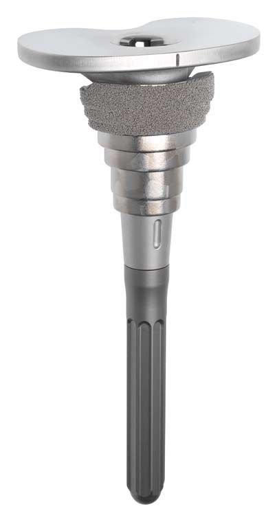
Reaming the Medullary Canal
          T-handle
                                Assemble the straight reamer to the T-handle. If
                                power reaming, it will be necessary to attach the
                                modified Hudson adaptor to the straight reamer.
                                The shaft of the reamer contains markings in 1 in.
                                (25.4 mm) increments. Fluted tibial stem lengths
                                are available in 75, 115 and 150 mm. Determine the
                                length and diameter of the prosthetic stem extension
                                with templates (cat. no. 2178-30-100) applied to
                                preoperative X-rays.
                     Straight
                     Reamer     Utilizing the reamer depth scale and the markings
                                on the straight reamer, ream to the pre-determined
                                depth so the pre-selected marking on the reamer
                                is positioned at the desired tibial resection level.
                                Sequentially open the canal with progressively
Fig. 10                         larger reamers until firm endosteal engagement is
                                established. [Fig. 10]

                                Note: Simple cortical contact should not be construed as
                                engagement.

                                The fixed relationship of the reamer to the cortices
                                ensures the secure fit of the appropriate reamer
                                and, subsequently, the corresponding fluted stem.
                                It is equally important to not overream osteopenic
                                bone.

                                The size of the final reamer indicates the diameter
                                of the implant stem. The fluted tibial stems are
                                available in even sizes (10 through 24 mm). Perform
                                final reaming with an even-sized reamer.

                                Refer to page 18 for cemented stem preparation.

                                                                                       8
Preparation of the Metaphyseal Bone – Tapered Reamer
For Diaphyseal Engaging Stem and
Metaphyseal Filling Sleeve
Tapered Reamer
Attach the appropriately sized stem trial to the end
of the reamer.
Note: Assembly of the stem trial may be aided by the
pre-attachment of the T-handle.
Tibial Resection
Taper ream to the planned proximal tibial resection Plane
level. [Fig. 11]
Note: Use the “cemented” taper reamer when requiring a
cement mantle or when utilizing a sleeve. Use the press-
fit tapered reamer when line-to-line fit is desired and a
sleeve will not be utilized.
Note: To avoid stem trial disengagement, do not reverse
ream. Fig. 11
At this point, intraoperatively determine if a
metaphyseal sleeve will be used.
Note: Metaphyseal sleeves are ideal to provide filling
of Engh type II or III defects in revision TKA. The steps
also provide progressive loading of the bone with porous
coating, which enhances fixation.
If a metaphyseal sleeve is selected, see page 12 in
order to broach the metaphyseal bone.
If a metaphyseal sleeve will not be used, see
page 10 to prepare for the proximal tibial resection.
9Proximal Tibial Resection – Tapered Reamer
Attach the 2 degree tibial cutting block to the I.M.
tibial referencing device. Attach the I.M. tibial
referencing device to the shaft of the tapered Lateral
reamer. Position the I.M. tibial referencing device Set Screw
with the pre-attached 2 degree cutting block onto
the shaft and allow it to descend to the proximal
tibial surface. Since considerable bone stock may
have been sacrificed in the primary total knee
arthroplasty (TKA), minimize the amount resected:
no more than 1-2 mm from the most prominent
condyle, managing residual defects of the
contralateral condyle with either prosthetic
augment or bone graft.
Resection is based on tibial deficiency and the level
of the joint line. Compensate deficiencies with
Fig. 12
sleeves, wedges and/or bone grafts. Advance the
cutting block to the anterior tibial cortex and lock
into position by tightening the knurled knob on the
outrigger. Preliminary rotational alignment is based
on the medial third of the tibial tubercle. Secure the
alignment device to the reamer shaft with the
lateral setscrew. [Fig. 12]
Pin the tibial cutting block so a minimal resection
is made from the proximal tibia. Utilize the stylus
when necessary. [Fig. 12]
Note: If a metaphyseal sleeve is to be used, tibial
resection using the 2 degree tibial cutting device is
unnecessary as the tibial resection will be performed
using the tibial sleeve broach. (see page 11, Fig. 15)
Note: There is a slotted and non-slotted end to the
Fig. 13
stylus. The difference between the two is 5 mm.
Remove the I.M. device while leaving the 2 degree
cutting block in place. Remove the tapered reamer
and resect the proximal tibia. [Fig. 13] (Maximum
saw blade thickness 1.5 mm)
Note: At this point determine whether a step wedge recommended that the step wedge be prepared after
is necessary on either the medial or lateral side to rotational position of both the femoral and tibial
augment a defect, or both sides in order to restore the components have been determined. For step wedge
joint line. If a wedge is necessary on one side, it is preparation see Appendix II (page 21).
10Preparation of the Metaphyseal Bone – Broach
Optional For Sleeve Utilization
Only
Note: The M.B.T. revision tibial tray will accept either a
tibial metaphyseal sleeve or a tibial step wedge if using
sleeve sizes 37, 45, 53 and 61 mm, but not both. Fig. 14
Attach the M.B.T. Revision Broach handle to the
smallest broach and then attach the appropriately
sized stem trial. The broaches are asymmetrical. Tibial
Resection
Plane
Position the “ANT” engraving on the broach
anteriorly.
Insert the broach into, then out of, the tibia until the
top surface of the broach is at the desired proximal
tibial resection level. Check for rotational stability.
If the broach is unstable or the defect is unfilled,
repeat with consecutively larger broaches until the
desired fit is achieved. [Fig. 14] Remove the broach
handle, leaving the last broach in place. Any defects
remaining can be filled with allograft or autologous
bone placed in intimate contact with the sleeve.
When utilizing a sleeve, resect the tibia
off the top of the broach. [Fig. 15]
Resect the proximal tibia utilizing
the top of the broach as a guide.
The top of the broach has a 2°
slope built in. The proximal cut should
be parallel to the top of the broach.
Fig. 15
Slide the tibial view plate which best covers the
proximal tibial over the broach post. Note the view
plate size, as it will dictate the size of the tibial base
plate that will be used. The tibial view plate
is transparent to help visualize tibial coverage.
[Fig. 16] The template matches the implant to aid
in orienting the tibial sleeve to the tibial base during
assembly.
Fig. 16
11Final Preparation of the Tibia
Place the knee in full extension and determine canal. Assess proximal tibial coverage and rotation
appropriate rotation of the tibial tray. [Fig. 17] of tibial component. Impact the appropriate keel
punch (utilize the cemented keel punch if a cement
Mark the appropriate rotation with electro- mantle is desired or the press-fit keel punch if line-
cautery on the anterior tibial cortex at the to-line contact is desired). [Fig. 18] The base plate
center and sides of the alignment handle. should be positioned to provide the best coverage
of the tibial condylar surface.
Position the tibial tray trial with stem extension,
and sleeve trial if applicable (sleeve trial allows Disconnect the universal handle, leaving the keel
20 degrees of rotation) into the prepared tibial punch in place for trial reduction. [Fig. 19]
Fig. 17
Fig. 18 Fig. 19
12Assembling the Prosthesis
Tibial Sleeve Assembly Wedge Assembly
Note: It is imperative to assemble the sleeve prior to Note: To aid wedge assembly, attach
stem attachment. wedge prior to stem attachment.
Note: Sleeves and step wedges can only be used together A
if using a 29 mm sleeve. Assemble
B the designated wedge to the
tray
C and secure using the
Remove trial component in one piece (use as guide appropriate
D screw. Carefully
for assembly of implants). tighten
E with the large T-handle
torque
F driver until an audible
Place the M.B.T. revision tray on a firm, stable, click
G is discerned, ensuring
padded surface. Set the tibial sleeve in an aH full and permanent
orientation that matches the prepared canal. interlock.
I [Fig. 22]
Matching the orientation of the tray/sleeve trial is J
helpful in determining appropriate rotation of the K
final tibial tray/sleeve implant. [Fig. 20] The sleeve L
can rotate 20 degrees internally or externally. M
N
Fig. 22
Using the sleeve impactor and a mallet, impact the
O
sleeve onto the M.B.T. revision tray. Deliver several P
strikes to engage the two components. [Fig. 21]
SQtem Component Assembly
R
Attach
S the tibial stem extension to the prosthetic
tray using the two appropriate wrenches to ensure
T
full
U engagement. [Fig. 23]
V
W
X
Y
Z
T
Fig. 23
Fig. 20 Fig. 21
13Fig. 24
Implanting the Tibial Component
Thoroughly cleanse the site with pulsatile lavage.
Where the prepared tibial surface is eburnated,
perforate with small drill holes to facilitate
penetration of methyl methacrylate. [Fig. 24] Pack
residual small cavitory bone defects with cancellous
autograft, if available, or allograft. Apply methyl
methacrylate cement to the proximal tibial surface
or directly to the underside of the tibial tray
Fig. 26
component.
Note: Refer to Table 1 on page 15 to note
appropriate set time for DePuy’s bone cement.
When a fluted stem or a fluted stem with a
metaphyseal filling sleeve is used, ensure the
medullary canal remains free of cement. Clear all
extruded cement with a curette. [Figs. 25 and 26]
Fig. 25
14Bone Cement
Table 1: Comparison of Phases—Overall Set Time at 65˚F
DePuy 1 6.5 minutes work 11.0 overall
SmartSet™ HV 8.0 minutes work 12.5 overall
HV
MV
Endurance™ 8.0 minutes work 14.0 overall
DePuy 3 5.5 minutes work 11.5 overall
Minutes: 5 10 15
Mix Pick-Up Work Time Final Set
15Trial Reduction
When femoral rotation is known, place the revision Note: With constrained femoral and tibial components
stem extension into the cone of the M.B.T. revision in trial reduction, it may be appropriate to cement the
implant. Seat the appropriate trial insert in the trial tibial tray implant and the femoral implant using the
post/tray. [Fig. 27] The trial femoral component insert trial. This will allow visibility of final rotation.
remains in place. Fully extend the knee to maintain
pressure as the cement polymerizes. [Fig. 28] After
cement polymerization, cement the femoral
component.
Revision Trial Post
Fig. 27
Fig. 28
16The Tibial Insert
Perform reduction. Where indicated, substitute an
appropriate replacement trial insert.
Subsequently remove the trial insert and trial post.
Introduce the permanent insert into the implanted
tibial tray. Due to the cone length, it is important
to adequately deliver the tibia forward in order to
place the insert in the tray. [Fig. 29]
Closure
At closure, put the knee through a range of motion
from full extension to flexion to confirm patellar
tracking and the integrity of capsular closure, with
specific attention to extensor mechanism balance.
Fig. 29
17The Cemented Tibial Stem Extensions
I
Cemented Stem Reamer
nd i x
Align the tibial tray and secure with
two fixation pins inserted through the
holes designated. [Fig. 30]
A pp e
Seat the M.B.T. revision drill bushing
onto the tibia trial. Place in the
posterior holes.
Place the cemented drill bushing into
the M.B.T. revision drill bushing. Fig. 30
[Fig. 31]
Use the “cemented” reamer to ream to
the predetermined selected depths for
tray only or the tray with a 30 or 60 mm
cemented stem.
Remove the reamer and “cemented”
bushing, leaving the tray trial and
M.B.T. revision drill bushing in place.
[Fig. 32]
Cemented Drill
Bushing
Note: Only a 13 mm diameter cemented
stem should be used in conjunction with M.B.T. Revision
Drill Bushing
the M.B.T. revision tray to avoid a step
off at the stem/tray junction.
Fig. 31
Fig. 32
18Modified
Tapered Reamer Hudson
Adapter
Assemble the revision reamer adapter
onto the cemented tapered reamer.
Next, attach the modified Hudson
adapter to the tapered reamer, if
power reaming.
Attach the appropriately sized
cemented stem trial (13 x 30 mm or Revision
Reamer
13 x 60 mm) to the tapered reamer if Adapter
utilizing a cemented stem extension.
[Fig. 33]
Ream until the revision reamer adapter
is flush with the M.B.T. revision drill
bushing. [Fig. 34]
Note: To avoid stem trial disengagement,
do not reverse ream.
Fig. 33
Fig. 34
19Tibial Keel Preparation
Place the knee in full extension and
determine appropriate rotation of the
tibial tray.
Mark the appropriate rotation with
electrocautery on the anterior tibial cortex
at the center and sides of the alignment
handle.
Assemble the appropriate stem trial to the
M.B.T. revision tray trial and seat in the
prepared bone bed.
Impact the cemented keel punch if a cement
mantle is desired or the press-fit keel punch
if line-to-line contact is desired. [Fig. 35]
Disconnect the universal handle leaving
the keel punch in place for trial reduction
(if appropriate).
It is recommended that a cement restrictor
be placed at the appropriate level prior to
cementing the component. Use a cement gun
to fill the canal with methyl methacrylate.
Fig. 35
20II
Step Wedge Preparation
Step Wedge Augmentation
nd i x
Resection for supplementary tibial augmentation
may be based on the established position of the
trial tray. Remove the femoral trial to provide
A pp e
greater access. Confirm rotational alignment of
the tibial tray stem trial.
Secure the tray with two
fixation pins. Attach the
tray trial wedge cutting
attachment with the step wedge cutting
guide to the trial tray. Slide the block forward
to the anterior proximal tibia and secure in
place with two Steinmann pins through the
holes marked with . [Fig. 36]
Fig. 36
Unlock the block and slide the assembly out of the
block. Disconnect the handle from the trial tray.
Position the step wedge cutting block on the pins
so the appropriate cutting surface (5, 10 or 15 mm
step) is at the deficient
condyle. [Fig. 37]
Fig. 37
21Trim the tibia accordingly with an oscillating saw
so the cut does not extend beyond the central riser.
Remove the block and pins. [Fig. 38]
Step Wedge
Cutting Block
Fig. 38
Fig. 39
Assemble the trial wedge to the appropriate tibial
tray trial and introduce into the prepared site.
Perform minimal correction with a bone file where
indicated to ensure maximal contact. [Fig. 39]
22Confirm positioning, alignment and security of the
tray assembly. If there is old cement or sclerotic
bone, relieve this first through the trial tray with a
saw blade or burr prior to punching. Position the
M.B.T. revision tibial keel punch at the tray and
cancellous bone interface and impact into the
keel configuration. Leave the punch in place and
perform a final trial reduction if necessary. [Fig. 40]
Note: Utilize the “cemented” keel punch when a cement
mantle is desired.
Alternative Step Wedge
Preparation
This is a “free-hand” resection. Assemble the wedge
trial and stem trial to the tibial tray trial. Position
the device slightly proximal to the planned resection
level. Make a conservative “free-hand” wedge
resection and then check cuts with the trials. [Fig. 41]
Fig. 41
Fig. 40
23III
Thick Tray Preparation
After impacting the cement or press-fit keel punch,
n d i x
remove the keel punch. Insert the M.B.T. thick tray
trial adapter (15 or 25 mm) onto the tibial tray trial.
[Figs. 42 and 43]
Note: The tibial tray trial must be used with the thick tray
A pp e
adapters as the two pieces equal the appropriate
sizing—15 or 25 mm.
Perform the final trial reductions utilizing the same
technique as the standard M.B.T. revision tray.
Implant assembly and implantation is also the same
as with the standard M.B.T. revision tray (see
Assembling the Prosthesis, on page 13, for more
information). If utilizing a wedge, refer to the step
wedge preparation in Appendix II.
Note: A tibial wedge can be used with all thick tray sizes,
except for size 2. Sleeves may be used with all thick trays.
Fig. 42
Fig. 43
24Implant Listing M.B.T. Revision Tray Cat. No. Size (mm) A/P M/L Stem Length Tray Thickness 1294-35-110 1 39.0 59.2 61.8 4.8 1294-35-115 1.5 40.7 61.8 61.8 4.8 1294-35-120 2 42.6 64.6 61.8 4.8 1294-35-125 2.5 44.2 67.1 61.8 4.8 1294-35-130 3 45.8 69.6 61.8 4.8 1294-35-140 4 49.3 74.9 61.8 4.8 1294-35-150 5 53.1 80.6 61.8 4.8 1294-35-160 6 57.2 86.8 61.8 4.8 1294-35-215 2+15 42.6 64.6 61.8 15 1294-35-225 2+25 42.6 64.6 61.8 25 1294-35-315 3+15 45.8 69.6 61.8 15 1294-35-325 3+25 45.8 69.6 61.8 25 1294-35-415 4+15 49.3 74.9 61.8 15 1294-35-425 4+25 49.3 74.9 61.8 25 M.B.T. Revision Sleeve Cat. No. Size (mm) A/P M/L Height 1294-54-000 29 26 29 40 1294-54-140 (Cemented) 29 26 29 40 1294-54-100 37 27 37 40 1294-54-110 45 27 45 40 1294-54-120 53 31 53 40 1294-54-130 61 34 61 40 25
M.B.T. Revision Augments
Cat. No.          Size (mm)             Cat. No.             Size (mm)
1294-56-110         1- 5                1294-56-130            3-5
1294-56-111         1-10                1294-56-131            3-10
1294-56-112         1-15                1294-56-132            3-15
1294-56-115         1.5-5               1294-56-135            4-5
1294-56-116         1.5-10              1294-56-136            4-10
1294-56-117         1.5-15              1294-56-137            4-15
1294-56-120         2-5                 1294-56-140            5-5
1294-56-121         2-10                1294-56-141            5-10
1294-56-122         2-15                1294-56-142            5-15
1294-56-125         2.5-5               1294-56-145            6-5
1294-56-126         2.5-10              1294-56-146            6-10
1294-56-127         2.5-15              1294-56-147            6-15

Express Care Kits - Implants
Kit No.       Kit Name
386A          M.B.T. Revision Sleeves
385A          M.B.T. Revision Trays Size 2-5
387A          M.B.T. Revision Stepped Wedges Size 2-5, 5, 10, 15 mm

Express Care Kits - Instruments
Kit No.       Kit Name
MBR100B       M.B.T. Revision Straight Reamers
MBR101B       M.B.T. Revision Prep Instruments
MBR102B       M.B.T./LCS Complete Femoral Revision Stem Trials
MBR103B       M.B.T. Revision Wedge Trials and Instruments

                                                                         26
Orthogenesis
Orthogenesis
LPS X-Small S-ROM S-ROM
LPS
Femur and Small Medium
XX-Small
S-ROM Femur Femur
Femur
X-Small Femur
Tray No. M/L 56.6 66.7 66.7 71.2
M.B.T.
Revision Tray
Size 1 1294-35-110 59.2
M.B.T.
Revision Tray
Size 1.5 1294-35-115 61.8
M.B.T.
Revision Tray
Size 2 1294-35-120 64.6
M.B.T.
Revision Tray
Size 2.5 1294-35-125 67.1
M.B.T.
Revision Tray
Size 3 1294-35-130 69.6
M.B.T.
Revision Tray
Size 4 1294-35-140 74.9
M.B.T.
Revision Tray
Size 5 1294-35-150 80.6
M.B.T.
Revision Tray
Size 6 1294-35-160 86.8
Orthogenesis LPS inserts must match S-ROM or Orthogenesis LPS femurs size-to-size. For example, xx
small femur = xx small polyethylene; small femur = small polyethylene etc.
M.B.T. Revision Trays LCS Complete Revision Tibial Inserts (RPS and VVC)
Sizes Small Small+ Medium Standard Standard+ Large Large+
Size 1 (1294-35-110)
Size 1.5 (1294-35-115)
Size 2 (1294-35-120)
Size 2.5 (1294-35-125)
Size 3 (1294-35-130)
Size 4 (1294-35-140)
Size 5 (1294-35-150)
Size 6 (1294-35-160)
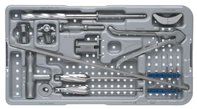
27M.B.T. Revision Prep Sterilization
Top Insert Cat. No. 2178-64-100
A
B
D
C F G
E
H
I
J
L
K M
N
Description Size Cat. No.
A Cemented Stem Reamer 13 mm 2178-63-185
B 2-Degree Cutting Block 2178-40-086
C Reamer Adapter 2178-63-128
D Tibial Punch Press-fit 2178-63-118
E Tibial Punch Cemented 2178-63-120
F Pin Holder .125 in. 2490-94-000
G SP2 Pin Puller 96-6515
H Drill Bushing 2178-63-100
I SP2 I.M. Rod 400 mm 96-6120
J I.M. Rod Handle 99-2011
K Cemented Bushing 13 mm 2178-63-196
L Tapered Press-fit Reamer 2178-63-104
M Tapered Cemented Reamer 2178-63-106
N Steinmann Pins 86-9117
28M.B.T. Revision Prep Sterilization
Base and Bottom Insert Cat. No. 2178-64-100
A F
B K L
G
C N
H
M L
D I Q
O
E J
P
R
Description Size Cat. No.
A 2-Degree Broach 29 mm 2178-63-109
B 2-Degree Broach 37 mm 2178-63-111
C 2-Degree Broach 45 mm 2178-63-113
D 2-Degree Broach 53 mm 2178-63-115
E 2-Degree Broach 61 mm 2178-63-117
F Sleeve Trial 29 mm 2294-54-000
G Sleeve Trial 37 mm 2294-54-100
H Sleeve Trial 45 mm 2294-54-110
I Sleeve Trial 53 mm 2294-54-120
J Sleeve Trial 61 mm 2294-54-130
K M.B.T. Revision Tibial Broach Handle 96-6521
L I.M. Tibial Alignment Device 96-6315
M Tibial Stylus 2178-40-045
N Sleeve Impactor 2178-63-124
O Femoral Sleeve/Stem Impactor 2178-63-126
P Universal Handle 96-6520
Q Tray Impactor 96-5383
R View Plates Size Cat. No.
1 2178-65-110
1.5 2178-65-115
2 2178-65-120
2.5 2178-65-125
3 2178-65-130
4 2178-65-140
5 2178-65-150
6 2178-65-160
29Revision Reamers Sterilization Tray
Top Insert Cat. No. 2178-64-105
B C
A
D E
F
G
Description Size Cat. No.
A Press-fit Rod Wrench 86-5189
B Sleeve Guide 12 mm 2178-63-187
C Sleeve Guide 14 mm 2178-63-188
D Reamer Depth Scale 2178-63-102
E Revision Femoral/Tibial/Sleeve Clamp 2178-63-134
F I.M. Initiator Drill Tibial 9 mm 2189-03-000
G M.B.T. Revision Reamers Size Cat. No.
10 mm 2178-63-170
11 mm 2178-63-171
12 mm 2178-63-172
13 mm 2178-63-173
14 mm 2178-63-174
15 mm 2178-63-175
30Revision Reamers Sterilization Tray
Base and Bottom Insert Cat. No. 2178-64-105
A B
C
D
E
H
F
G I
Description Size Cat. No.
A M.B.T. Revision Reamers 16 mm 2178-63-176
17 mm 2178-63-177
18 mm 2178-63-178
19 mm 2178-63-179
20 mm 2178-63-180
21 mm 2178-63-181
22 mm 2178-63-182
23 mm 2178-63-183
24 mm 2178-63-184
B Reamer T-handle 2178-63-137
C Hudson Adapter 2178-63-136
D I.M. Rod Sleeve Guide 16 mm 2178-63-189
E I.M. Rod Sleeve Guide 18 mm 2178-63-190
F I.M. Rod Sleeve Guide 20 mm 2178-63-191
G I.M. Rod Sleeve Guide 22 mm 2178-63-192
H I.M. Rod Sleeve Guide 24 mm 2178-63-193
I I.M. Rod Sleeve Guide 26 mm 2178-63-194
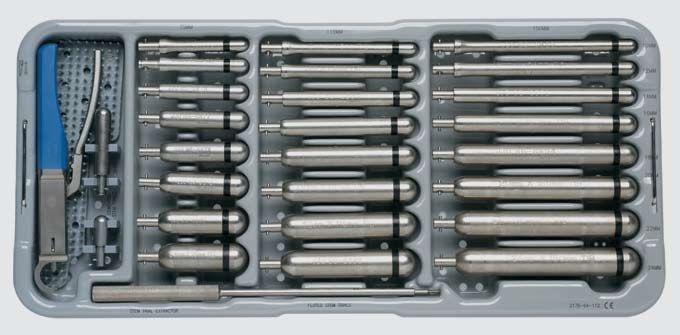
31Revision Stem Trials & Instruments Sterilization Tray
Top Insert Cat. No. 2178-64-110
E F G
A
B
C
D
Description Size Cat. No. Description Size Cat. No.
A Revision Femoral/Tibial/Sleeve Clamp 2178-63-134 F Fluted Tibial Rod Trials 10 x 115 86-6882
B Tibial Cemented Stem Trial 13 x 60 2-3 86-6502 12 x 115 86-6883
C Tibial Cemented Stem Trial 13 x 30 1.5-3 86-6501 14 x 115 86-6884
D Stem Trial Extractor 86-5226 16 x 115 86-6885
E Fluted Tibial Rod Trials Size Cat. No. 18 x 115 86-6886
10 x 75 86-6874 20 x 115 86-6887
12 x 75 86-6875 22 x 115 86-6888
14 x 75 86-6876 24 x 115 86-6889
16 x 75 86-6877 G Fluted Tibial Rod Trials 10 x 150 86-6890
18 x 75 86-6878 12 x 150 86-6891
20 x 75 86-6878 14 x 150 86-6892
22 x 75 86-6880 16 x 150 86-6893
24 x 75 86-6881 18 x 150 86-6894
20 x 150 86-6895
22 x 150 86-6896
24 x 150 86-6897
32Revision Stem Trials & Instruments Sterilization Tray
Base and Bottom Insert Cat. No. 2178-64-110
D E F
A B
C
Description Size Cat. No. Description Size Cat. No.
A Press-fit Rod Wrench 86-5189 E Fluted Tibial Rod Trials 10 x 115 86-6882
B Tibial Cemented Stem Trial 13 x 60 2-3 86-6502 12 x 115 86-6883
C Tibial Cemented Stem Trial 13 x 30 1.5-3 86-6501 14 x 115 86-6884
D Fluted Tibial Rod Trials Size Cat. No. 16 x 115 86-6885
10 x 75 86-6874 18 x 115 86-6886
12 x 75 86-6875 20 x 115 86-6887
14 x 75 86-6876 22 x 115 86-6888
16 x 75 86-6877 24 x 115 86-6889
18 x 75 86-6878 F Fluted Tibial Rod Trials 10 x 150 86-6890
20 x 75 86-6878 12 x 150 86-6891
22 x 75 86-6880 14 x 150 86-6892
24 x 75 86-6881 16 x 150 86-6893
18 x 150 86-6894
20 x 150 86-6895
22 x 150 86-6896
24 x 150 86-6897
33M.B.T. Revision Tray Trials
& Wedge Instruments Sterilization Tray
Top Insert Cat. No. 2178-64-115
A
B
C
A
B
C
Description Size Cat. No. Description Size Cat. No.
A M.B.T. Step Wedge Trials 5 mm C M.B.T. Step Wedge Trials 15 mm
1 2294-56-110 1 2294-56-112
1.5 2294-56-115 1.5 2294-56-117
2 2294-56-120 2 2294-56-122
2.5 2294-56-125 2.5 2294-56-127
3 2294-56-130 3 2294-56-132
4 2294-56-135 4 2294-56-137
5 2294-56-140 5 2294-56-142
6/7 2294-56-145 6/7 2294-56-147
B M.B.T. Step Wedge Trials 10 mm
1 2294-56-111
1.5 2294-56-116
2 2294-56-121
2.5 2294-56-126
3 2294-56-131
4 2294-56-136
5 2294-56-141
6/7 2294-56-146
34M.B.T. Revision Tray Trials
& Wedge Instruments Sterilization Tray
Base and Bottom Insert Cat. No. 2178-64-115
B B B B
G
C
F
A
D
I
E
H
J
B B B B
Description Size Cat. No. Description Size Cat. No.
A M.B.T. Tibial Trials C Cut Block 2178-63-122
1 2294-36-110 D Screw Driver 86-0277
1.5 2294-36-115 E Wedge Cut Attachment 2178-63-130
2 2294-36-120 F Alignment Handle 96-6330
2.5 2294-36-125 G Alignment Rods 99-1016
3 2294-36-130 H Trial Post 2178-63-132
4 2294-36-140 I Torque Driver 86-0284
5 2294-36-150 J Fixation Pins 2178-30-123
6 2294-36-160
B Tray Trials with Stem Size Cat. No.
1 2294-35-111
1.5 2294-35-115
2 2294-35-120
2.5 2294-35-125
3 2294-35-130
4 2294-35-140
5 2294-35-150
6 2294-35-160
35LCS® Complete™ – P.F.C.® Sigma™ RP Mobile Bearing Total Knee System
Important
This Essential Product Information sheet does not include all of the information necessary for selection and use of a device. Please see full labeling for all necessary information.
Indications
Cemented Use:
The LCS® Complete™ – P.F.C.® Sigma™ RP Mobile Bearing Total Knee System is indicated for cemented use in cases of osteoarthritis and rheumatoid arthritis. The RPF insert and femoral
component are indicated where a higher than normal degree of postoperative flexion is required. The rotating platform prosthesis and modular revision components are indicated for revision
of failed knee prostheses.
Uncemented Use:
The porous coated Keeled and Non Keeled M.B.T.™ (Mobile Bearing Tibial) Tray configurations of the LCS Total Knee System are indicated for noncemented use in skeletally mature individuals
undergoing primary surgery for reconstructing knees damaged as a result of noninflammatory degenerative joint disease (NIDJD) or either of its composite diagnoses of osteoarthritis and
post-traumatic arthritis pathologies. The Rotating Platform device configuration is indicated for use in knees whose anterior and posterior cruciate ligaments are absent or are in such condition as to
justify their sacrifice. The P.F.C. Sigma RP Curved bearings when used with the P.F.C. Sigma Cruciate Retaining Femoral Component can be used in posterior cruciate ligament retaining procedures.
Contraindications
The use of the LCS Complete – P.F.C. Sigma RP Mobile Bearing Total Knee System is contraindicated in:
• the presence of osteomyelitis, pyrogenic infection or other overt infection of the knee joint;
• patients with any active infection at sites such as the genitourinary tract, pulmonary system, skin or any other site. Should a patient have any infection prior to implantation, the foci of the infection
must be treated prior to, during and after implantation;
• patients with loss of musculature or neuromuscular compromise leading to loss of function in the involved limb or in whom the requirements for its use would affect recommended rehabilitation
procedures;
• patients with severe osteoporosis or other metabolic bone diseases of the knee.
• patients with any of the following conditions:
• lesions of the supporting bone structures (e.g. aneurysmal or simple bone cysts, giant cell tumor or any malignant tumor);
• systemic and metabolic disorders leading to progressive deterioration of solid bone support;
• the presence of severe instability secondary to advanced loss of osteochondral structure or the absence of collateral ligament integrity, fixed deformities greater than 60° of flexion, 45° of genu
varus or valgus,
• known drug or alcohol addiction;
• skeletally immature individuals and the presence of allergic reaction to implant metals or polyethylene are also contraindications for the noncemented, porous coated, M.B.T. and LCS Complete
– P.F.C. Sigma RP Mobile Bearing device configurations, and for the cemented use of all device configurations of the LCS Complete – P.F.C. Sigma RP Mobile Bearing Total Knee System.
Contraindications for use without Cement
Noncemented use of the Porous Coated Keeled or Non-Keeled M.B.T. Tray device configurations is contraindicated in patients with sufficient loss in quantity or quality of bone stock (as determined on X-ray)
such that successful noncemented fixation is unlikely. Additional contraindications may become apparent at the time of surgery. These include:
• vascular deficiency at the bone site;
• inadequate bone stock to assure both a firm press fit and close apposition of the cut bone surfaces to the prosthesis;
• the inability to make bone cuts so as to assure both correct component position and intimate apposition of bone and prosthetic surfaces;
• inadequate bone quality (e.g. severe osteoporosis) and lack of stability of the implanted components.
In the presence of any of the above conditions the components should be fixed with cement.
Warnings and Precautions
Components labeled for “Cemented Use Only” are to be implanted only with bone cement. The following conditions tend to adversely affect knee replacement implants: excessive patient weight, high levels
of patient activity, likelihood of falls, poor bone stock, metabolic disorders, disabilities of other joints. The P.F.C. stem extensions can only be used with M.B.T. revision trays and LCS Complete Revision and
Modular femoral components.
Adverse Events
The following are the most frequent adverse events after knee arthroplasty: change in position of the components, loosening, bending, cracking, fracture, deformation or wear of one or more of the
components, infection, tissue reaction to implant materials or wear debris; pain, dislocation, subluxation, flexion contracture, decreased range of motion, lengthening or shortening of leg caused by
improper positioning, looseness or wear of components; fractures of the femur or tibia.
For more information about DePuy products, visit our web site at www.kneereplacement.com.
3.5M0506 Printed in USA.
0612-49-500 (Rev. 1) © 2006 DePuy Orthopaedics, Inc. All rights reserved.You can also read