SPARK PLUGS Discovering DENSO Technology - DENSO Europe B.V.
←
→
Page content transcription
If your browser does not render page correctly, please read the page content below

SPARK PLUGS

                                              SPARK PLUGS Discovering DENSO Technology
                                                                                         Discovering DENSO Technology

DENSO Europe B.V.
Hogeweyselaan 165, 1382 JL Weesp
The Netherlands

Tel: +31 294 493 493 I Fax: +31 294 417 122
marketing@denso.nl

www.denso-am.eu
DENSO HIGHLIGHTS

DENSO Aftermarket Europe is part of DENSO                              Contents
Corporation, one of the world’s top three
manufacturers of advanced automotive technology,                       1.    INTRODUCTION TO SPARK PLUGS......................................................................................................... 2
                                                                             1.1. Spark plugs: a critical part of the combustion process...................................................................................... 2

systems and components.                                                      1.2. Operating requirements for modern spark plugs................................................................................................ 3
                                                                             1.3. Different spark plugs for different engines.......................................................................................................... 4

                                                                       2.    4-STROKE ENGINE OPERATION AND COMBUSTION PROCESS............................................................ 6
                                                                             2.1. The 4-stroke cycle: intake, compression, ignition, exhaust................................................................................ 6
Founded in 1949, DENSO became a pioneer of quality
                                                                       3.    COIL IGNITION SYSTEM OPERATION....................................................................................................... 8
products for the automotive industry, supplying a large                      3.1.    The tasks of an ignition system............................................................................................................................ 8
range of original equipment to every major vehicle                           3.2.    The introduction of coil ignition............................................................................................................................ 8
                                                                             3.3.    Ignition coils: transforming a low voltage into a high voltage............................................................................. 9
manufacturer in the world. In fact, you’ll find original                     3.4.    Coil charge-up time and dwell period.................................................................................................................11
DENSO parts in nine out of ten cars on the road.                             3.5.    Ignition timing: providing the spark at the correct time......................................................................................12

                                                                       4.    MECHANICAL AND ELECTRONIC IGNITION SYSTEMS..........................................................................16
We are also proud to bring that unique expertise to the independent          4.1. Basic mechanical ignition system.......................................................................................................................16
aftermarket. Our technologically advanced product ranges are                 4.2. Early type electronic ignition systems............................................................................................................... 20
                                                                             4.3. Modern electronic ignition systems................................................................................................................... 21
specifically selected for distributor and end-user customers and
feature the same specifications as those parts used for the original   5.    THE COMBUSTION PROCESS IN DETAIL...............................................................................................24
equipment manufacturers (OEMs).
                                                                             5.1.    The combustion of fuel and oxygen................................................................................................................... 24
                                                                             5.2.    Achieving good combustion.............................................................................................................................. 26
                                                                             5.3.    Causes and problems of poor combustion....................................................................................................... 27
Spark plugs are one of DENSO’s main specialisms. Our continual               5.4.    Pollutants and harmful emissions created during combustion......................................................................... 29
research and development work has led to many of the sector’s                5.5.    Reducing emissions and improving fuel economy............................................................................................ 30
most important innovations, including U-groove technology,
the world’s smallest iridium tip and the first protruding ground       6.    SPARK PLUGS........................................................................................................................................ 32
electrodes. As a major sponsor and technical partner of Toyota               6.1.    The key to combustion....................................................................................................................................... 32
Gazoo WEC, Volvo Cyan WTCC, Toyota WRC, Subaru WRT and                       6.2.    Performance requirements................................................................................................................................ 32
other motorsport teams, we also know all about high performance              6.3.    Spark plug structure........................................................................................................................................... 33
and use that experience to inform our iridium and racing ranges.             6.4.    Electric spark and required spark voltage......................................................................................................... 35
                                                                             6.5.    Operating conditions affecting spark plug voltage........................................................................................... 36
                                                                             6.6.    Heat-range.......................................................................................................................................................... 39
With a spark plug to suit every application and motoring need,               6.7.    Flame quenching affecting flame generation and flame growth .......................................................................41
you can rely on DENSO.
                                                                       7.    DENSO TECHNOLOGIES: IMPROVING SPARK PLUG PERFORMANCE................................................ 42
                                                                             7.1.    DENSO development.......................................................................................................................................... 42
                                                                             7.2.    Electrode materials............................................................................................................................................. 43
                                                                             7.3.    Centre materials................................................................................................................................................. 44
                                                                             7.4.    Ground electrode................................................................................................................................................ 45
                                                                             7.5.    Other technologies used on DENSO Spark Plugs..............................................................................................47
                                                                             7.6.    Future trends...................................................................................................................................................... 48

                                                                       8.    DENSO RANGE....................................................................................................................................... 50
                                                                             8.1.    Direct Fit............................................................................................................................................................. 50
                                                                             8.2.    Twin Tip............................................................................................................................................................... 52
                                                                             8.3.    Iridium Power...................................................................................................................................................... 53
                                                                             8.4.    Iridium Racing..................................................................................................................................................... 54

                                                                       9.    UPGRADE YOUR SPARK PLUGS........................................................................................................... 56
                                                                             9.1.    Why upgrade your spark plug?.......................................................................................................................... 56
                                                                             9.2.    Power output...................................................................................................................................................... 57
                                                                             9.3.    Fuel economy and emissions............................................................................................................................. 58
                                                                             9.4.    Smooth idling, misfires and starting.................................................................................................................. 59
                                                                             9.5.    LPG and CNG converted cars........................................................................................................................... 60
                                                                             9.6.    Tuning and racing............................................................................................................................................... 61

                                                                       10.   FAQ, INSTALLATION AND TROUBLE SHOOTING................................................................................... 62
                                                                             10.1. FAQ..................................................................................................................................................................... 62
                                                                             10.2. Correct installation of spark plugs..................................................................................................................... 64
Author                                                                       10.3. Trouble shooting................................................................................................................................................. 65
Wouter Knol – DENSO Aftermarket Application Engineer
Co-authors
Peter Coombes – Technical writer
Gilbert Couvert – DENSO Aftermarket Product Manager
1. INTRODUCTION
1.1. Spark Plugs: a critical part of the combustion process 2
1.2. Operating requirements for modern spark plugs 3
1.3. Different spark plugs for different engines 4
TO SPARK PLUGS
1.1 Spark plugs: a critical part of the combustion process 1.2. Operating requirements for modern spark plugs
Internal combustion engines: creating heat to produce power The spark plug is the critical component for the combustion Temperature
Internal combustion engines produce power by harnessing the process The spark plug Although the spark plug electrodes can initially be exposed
energy that is produced when the air in the cylinders is heated At exactly the right time, the ignition system delivers a short burst operates with to temperatures as high as 10,000°C during the very brief period
by the combustion of fuel. The heat causes the air to rapidly of high voltage to the spark plug, which creates the spark across voltages as high as when the spark occurs, during the more prolonged combustion
expand, which forces the piston to move along the cylinders a small gap at the tip of the spark plug. At the centre or kernel 40,000 volts or more process the spark plug housing and electrodes are exposed to
and then turn the crankshaft (Fig 1.1). of the spark (Fig 1.2), the temperature can briefly reach or even temperatures in the area of 3,000°C. But there are also rapid
exceed 10,000°C, which provides sufficient heat to ignite a small changes in temperatures, such as when a fresh charge of air
portion of the mixture that is adjacent to the spark plug tip. The spark plug enters the cylinder during the intake stroke, which has an
The spark plug housing and immediate cooling effect on the spark plug that has just been
A spark produced by the housing and electrodes electrodes are exposed to the high combustion temperatures.
spark plug ignites the air / can be exposed to exposed to rapid
fuel mixture to start the temperatures as high temperature changes As well as the possibility of the high temperatures causing
combustion process as 3,000°C during during the 4-stroke damage to the electrodes and the spark plug housing, there
combustion engine cycle is also the possibility that part of the spark plug could remain
so hot that it causes pre-ignition, which is when a hot spot on
The combustion of the air / Spark temperature the spark plug has already ignited the air / fuel mixture before
fuel mixture creates the heat at the electrodes The spark plug housing the spark occurs. This early or advanced ignition of the air / fuel
that causes the air to expand can reach as high and electrodes are mixture creates premature combustion, which causes the
and force the piston down the as 10,000°C exposed to pressures pressure rise and expansion of gasses to occur too soon.
cylinder to turn the crankshaft of 50-bar or more The premature expansion and associated pressure rise will then
during combustion try to force the piston down the cylinder before the piston has
reached the top of the compression stroke (see section 5.3).
Fig 1.3 The spark plug must operate in a very hostile environment
Reliability and durability
Irrespective of engine design, the region within the cylinder where
Fig 1.1 Ignition, combustion and power combustion takes place provides a very hostile environment.
During operating conditions, The spark plug must provide a high temperature spark to ignite
the temperature of the spark the air / fuel mixture; and the spark plug must be able to continue
The combustion process is therefore one of the most important can reach 10,000°C to provide a spark for many thousands of kilometres and many
parts of the whole engine operating cycle; if combustion is millions of combustion cycles.
not efficient the engine will not produce the required power. Fig 1.2 Spark temperature
Additionally, inefficient combustion will create high levels of Voltage and spark
pollutants and result in excessive fuel consumption. The primary task of the spark plug is to make use of high voltages
This initial combustion then produces a hot flame that spreads to produce a very rapid hot intense spark. The voltages are typically
To achieve efficient combustion, the air in the cylinder must be to the rest of the mixture thus creating combustion in all of the in the range of 10 thousand to 40 thousand volts (10kV to 40kV),
mixed with a small quantity of fuel in an exact ratio. The mixture compressed air / fuel mixture in the combustion chamber. but the trend is now towards voltages of 45kV and higher. The
is then compressed within the cylinder by the movement of the spark plug construction must therefore include good insulation
piston, which squeezes the mixture into a small space, referred It is the heat produced by the combustion process that then between the different spark plug components to ensure that the
to as the combustion chamber (see chapter 2). causes the compressed gasses in the cylinder to expand and high voltage does not escape or short out to other components.
push the piston along the cylinder; but it is the spark plug that
The compressing of the air and fuel mixture does in fact create heat is the critical component in creating the initial high temperature
but that is insufficient to ignite the mixture, therefore an additional that starts the whole combustion process.
source of heat is required to initiate combustion. The additional
heat is provided by creating a spark (a hot electric arc) using a
spark plug that is strategically located in the combustion chamber.
The air in the atmosphere (and therefore in the cylinder) is made up of
approximately 78% nitrogen and approximately 21% oxygen along with
small percentages of argon, carbon dioxide and some other gasses.
The fuel (petrol /gasoline) is made up of hydrogen and carbon. During
the combustion or burning process, which releases the energy stored
in the fuel, many of the gasses and elements in the air and fuel chemically
react to form different gasses. Therefore, when we refer to the expansion
of the air in the cylinder, it is in fact an expansion of a mix of gasses.
2 3
1. INTRODUCTION TO SPARK PLUGS AND COMBUSTION
Pressure The many different engine designs would in theory demand
High pressures of typically around 50-bar or more can be created The gaskets and insulator protect many different spark plugs with specific requirements and
during combustion, although these pressures can be much higher 5 many of the spark plug components specifications; however, by using advanced design features
on some high-performance engines. from exposure to high temperatures, DENSO is able to produce a relatively small range of spark plugs
pressures and voltages that can satisfy the requirements for many different engine types.
There must therefore be a good pressure seal between the Advanced, higher specification spark plugs can replace many
spark plug casing and the engine. But the construction of the spark plugs of lower specifications.
spark plug must also include internal sealing to prevent hot and 3
high pressure gasses passing between the different spark plug One advanced DENSO design feature, is the use of iridium, which
components (Fig 1.4). Apart from loss of pressure, if any gasses allows DENSO Iridium Spark Plugs to be produced with ultra-thin
are able to pass through the spark plug assembly, this would 4 6 (0.4 mm diameter) centre electrodes (Fig 1.5).
damage the spark plug components. Patented 0.4 mm
1 diameter iridium The iridium electrodes enable smaller plug gaps and lower voltages
7
Contaminants and fouling centre electrode to be used compared to using less advanced spark plug designs.
The combustion process produces many different contaminants As well as having higher strength and low electrical resistance
including burnt fuel and oil deposits that can build up on the spark 2 8 compared with more traditional electrode materials, iridium is able
plug and affect performance. So although the spark plug must to withstand higher temperatures and is therefore more durable.
not become too hot, it must retain sufficient heat to burn off the 4
contaminants and prevent fouling of the spark plug (see section 6.6). Fig 1.5 DENSO Iridium Spark Plug The use of iridium electrodes as well as other spark plug design features
are covered in detail in chapters 6, 7 and 8.
Conclusion
The important features of spark plug design are therefore the 9
ability to withstand high temperatures and temperature changes, 10
along with the ability to withstand high pressures; but at the same
time the spark plug must operate with high voltages to produce a
hot spark every few thousandths of a second for the whole of the DENSO HIGHLIGHT
spark plug’s service life.
1 Housing 6 Centre shaft (stem)
To prevent the damaging effects of high temperatures, the spark A DENSO Spark Plug for every engine
plug must be able to dissipate or transfer heat away from the spark 2 Gasket 7 Resistor
plug and through the engine casing. But importantly, if too much 3 Insulator 8 Electrode with copper
Unique spark plugs for OEMs
heat is passed away or dissipated from the spark plug, this can
then reduce the temperature of the spark and cause poor ignition 4 Ring gasket (2x) 9 Centre electrode
and combustion. Additionally, if too much heat is dissipated, the
When developing an engine, OEMs choose the spark plug based on their requirements. However,
5 Terminal 10 Ground electrode
spark plug might not be able to burn off the contaminants. with specific requirements for that specific engine, OEMs have different needs than the aftermarket.
Fig 1.4 DENSO Iridium Spark Plug
For the OEM, the benefits of a unique spark plug include: The DENSO alternative option
> A spark plug that performs at least to the minimum To help reduce this number, DENSO offers an alternative
requirements solution: by supplying an aftermarket spark plug that has higher
DENSO HIGHLIGHT > A spark plug that performs with an acceptable replacement performance than the original, DENSO can replace multiple
interval different spark plug types that often have only minor differences.
> A unique spark plug is usually the result of reaching minimum For example, the ‘DENSO Twin Tip’ range of high performance
The use of precious metals and special materials High quality performance and durability requirements at the lowest cost. spark plugs only requires 35 part numbers to cover 90% of the car
ceramic insulators parc. To achieve this, high performance spark plugs with unique
A unique spark plug comes at additional development cost, small diameter and wear resistant electrodes have been developed.
Materials used in DENSO Spark Plugs (such as the high quality but the quantities produced are often large enough to compensate
special ceramic insulators and the precious metals used in the for this extra cost. Conclusion
The Twin Tip range is developed from IAM perspective and
iridium and platinum alloys for electrodes) can withstand the very In the Independent Aftermarket (IAM), some spark plug features advanced technology that covers specifications of many
high temperatures in the engine and combustion chamber making Iridium and manufacturers gladly use these benefits to market their own spark plug types. It equals and often outperforms the OEM spark
platinum alloys unique spark plugs as the original plug. For example, DENSO plugs and enables the IAM to consolidate the spark plug range.
DENSO Spark Plugs one of the most durable in the market. also produces spark plugs that are exactly the same specification
for electrodes
as the original spark plug.
However, to offer a complete range that fits every car, 400+ spark
plugs would be needed.
1.3. Different spark plugs for different engines
Different designs of engine inevitably require different sizes of There are many other design features of spark plugs that can
spark plug that can vary in overall dimensions. The trend for narrow be influenced by specific operating conditions in different Nickel Spark Plug Platinum Spark Plug Iridium Spark Plug SIP Spark Plug Nickel TT Spark Plug Iridium TT Spark Plug
spark plugs for motorcycle applications began many years ago; engine designs. Temperatures and pressures within the different
but modern downsized car engines are now also fitted with these combustion chamber designs as well as the use of higher
narrow spark plugs that still have to withstand the same hostile voltages have an effect on the design of a spark plug. With the
operating conditions. continued focus on reducing emissions, spark plug design is
constantly evolving to suit the more stringent requirements that
are being imposed on each new generation of engines.
4 5
2. 4
-STROKE ENGINE OPERATION
2.1. The 4-stroke cycle: intake, compression, ignition, exhaust 6
AND COMBUSTION PROCESS
2.1. The 4-stroke cycle: intake, compression, ignition, exhaust
Developed by N. Otto in 1876, the 4-stroke engine, also known as (3) Ignition stroke (combustion or power stroke)
the Otto engine or the Spark Ignited (SI) engine, is based on the During the 3rd stroke (Fig 2.3), the combustion of the air / fuel
cycle of 4 processes, which are the intake, compression, ignition mixture creates the heat that causes the air to expand and force
and exhaust strokes. Intake valve the piston down the cylinder, which is effectively producing the The spark has The combustion of
opens allowing power to turn the crankshaft. Unlike in diesel engines which have ignited the air / fuel the air / fuel mixture
(1) Intake stroke air to enter the a much higher compression ratio, the compression stroke does mixture to start the creates the heat
During the 1st stroke, the piston moves down the cylinder (Fig 2.1), cylinder through The piston moves heat up the air / fuel mixture, but not enough to ignite. Therefore combustion process that causes the air
which creates a pressure that is lower than atmospheric pressure; the intake down the cylinder a spark plug is used to create a hot spark that provides the required to expand, which
and because the inlet valve is open, the air outside the cylinder manifold creating a lower heat to initiate the combustion process. then forces the
(which is at atmospheric pressure) will flow towards the lower pressure in the
piston to move
pressure in the cylinder. In effect, the movement of the piston cylinder In theory, the spark should be created at the exact time that the down the cylinder
creates a suction (or difference in pressure) that pulls in the air. piston reaches the top of the cylinder (Top Dead Centre or TDC)
when the piston is just about to move down the cylinder again.
When turbochargers or superchargers are fitted, the air is But because the mixture can take a few thousandths of a second
compressed, which forces even more air through the intake to ignite and completely combust (and then create the high
manifold into the cylinder. pressure in the cylinder), it is necessary to start the combustion
process slightly early or in advance of when the heat and expansion
For most engines already in use, the required small quantity of fuel will be are actually required. The spark plug will therefore usually provide
mixed with the air by injecting the fuel into the intake manifold during or Fig 2.1 Intake stroke the spark to initiate combustion whilst the piston is still approaching Fig 2.3 Ignition / power stroke
sometimes just before the intake stroke. However, some modern engines TDC at the end of the compression stroke (see section 4.3).
are fitted with direct fuel injection where the fuel is injected directly into the
cylinder during the intake stroke or (during some engine operating conditions) This advanced timing for the spark and the start of combustion
the fuel can be injected at the early stages of the compression stroke. Intake valve Exhaust valve then allows the remainder of the combustion process to progressively Exhaust
closed closed but rapidly take place and provide the heat to expand the gasses valve opens
(2) Compression stroke in the cylinder.
During the 2nd stroke (Fig 2.2), the intake valve is closed thus
sealing the cylinder and preventing any air or pressure escaping. Although we generally refer to this stroke as the ignition stroke,
The piston rises in the cylinder, which compresses the air and it can also be regarded as the combustion stroke or the power
fuel mixture to approximately 1/10th of its original volume (the Piston moving stroke because it is during this stroke when the air / fuel mixture
amount of compression depends on engine design). The pressure up the cylinder to combusts and produces the force that pushes the cylinder down
in the cylinder will in theory therefore be approximately 10 times compress the air and powers the engine. The piston rises
atmospheric pressure (10 bar) or even more under certain conditions fuel mixture into and forces the
if the engine is turbocharged or supercharged. the combustion (4) Exhaust stroke burnt gasses to
chamber During the 4th stroke (Fig 2.4), the exhaust valve is open and flow out of the
the continuing rotation of the crankshaft moves the piston up cylinder to the
the cylinder, which forces the burnt gasses to flow out of the exhaust system
cylinder into the exhaust system.
Following this 4th stroke, the exhaust valve closes and the
Fig 2.2 Compression stroke whole 4-stroke cycle can start again with the intake valve Fig 2.4 Exhaust stroke
opening and a fresh charge of air and fuel enters the cylinder
on a new intake stroke.
Alternative combustion engines
Most automobile engines operate using the 4-stroke cycle,
but some engines operate using a 2-stroke cycle or rotary type
Wankel principle. Although there are operating differences,
they all rely on compressing an air / fuel mixture, igniting it using
a spark plug and using the increased pressure to produce
rotational power.
6 7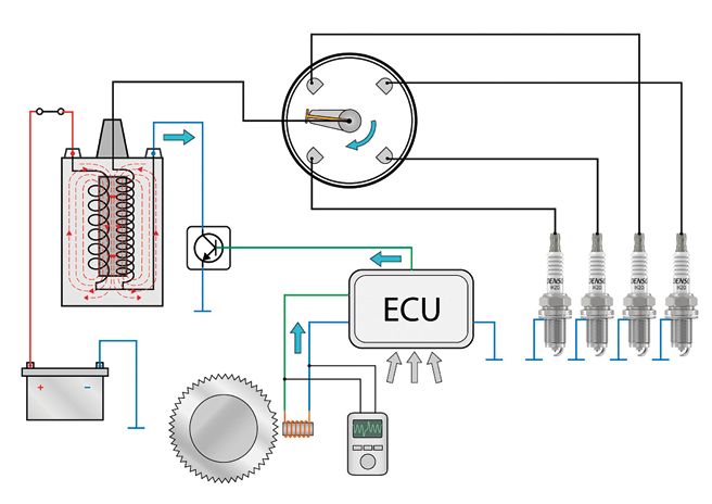
3. COIL IGNITION SYSTEM OPERATION
3.1. The tasks of an ignition system 8
3.2. The introduction of coil ignition 8
3.3. Ignition coils: transforming a low voltage into a high voltage 9
3.4. Coil charge-up time and dwell period 11
3.5. Ignition timing: providing the spark at the correct time 12
3.1. The tasks of an ignition system 3.3. Ignition coils: transforming a low voltage into a high voltage
Reliability, long maintenance intervals, helping to reduce emissions Two primary tasks
Ignition systems have evolved throughout the years from rather Ignitions systems must perform two primary tasks:
basic mechanical systems to the high-tech electronic systems one
can find in modern cars. Although modern engines operate with (1) Produce the high voltage for a spark
higher combustion temperatures and pressures, leaner air / fuel (2) At exactly the right time. Magnetic field
mixtures and higher engine speeds, the improvements in ignition created by
system design are constantly increasing reliability, fuel economy, the flow of an
maintenance intervals and engine performance. However, modern electric current
ignition systems must also accommodate the increased demand
for cleaner emissions.
Closed switch
Switch is open, allowing current
no current flows to flow through
through the coil the circuit
Power supply providing
3.2. The introduction of coil ignition an electric current
Fig 3.2 Using an electric current to create a magnetic field
With very few exceptions, ignition systems for modern The Kettering system (Fig 3.1) used a single ignition coil to provide
petrol /gasoline car and motorcycle engines operate using the high voltage that was then distributed to the spark plugs for all
ignition coils to create the high voltage that is required to produce of the cylinders. The high voltage from the ignition coil was passed To be able to produce the required high voltages, ignition coils
a spark at the spark plug. Since the 1970’s, ignition systems have to a rotor arm that effectively pointed the high voltage to a series of make use of the relationships that exist between electricity
changed considerably due to the use of electronics, but even electrical contacts located in the distributor assembly (one contact and magnetism.
modern coil ignition systems are clearly an evolution of the original for each cylinder). These contacts were then connected by spark
coil ignition systems that were introduced more than 100 years ago. plug wires to the spark plugs in a sequence that made it possible Using an electric current to create a magnetic field Permanent magnet S
to distribute the high voltage to the spark plugs in the correct When an electric current flows through an electrical conductor such moving so that the
The invention of the coil based ignition system is credited cylinder firing order. as a coil of wire, it creates a magnetic field around the coil (Fig 3.2). magnetic field moves
to the American inventor Charles Kettering who developed The magnetic field (or more precisely magnetic flux) is effectively across the coil of wire N
a coil ignition system that was originally fitted to Cadillac vehicles The Kettering ignition system progressively became almost the a store of energy that can then be converted back into electricity.
around 1910/1911. The use of an efficient coil ignition system only type of ignition system used for mass produced petrol /gasoline
was made possible because of the use of a battery that also cars until electronically switched and controlled ignition systems When the electric current is initially switched on, the current flow
provided electrical power to a starter motor (which was in fact started to replace mechanical ignition systems during the 1970’s progressively but rapidly increases to its maximum value. At the The change of
also developed by Kettering for the Cadillac). The battery, and 1980’s. (See section 4.1). same time, the magnetic field or flux will also progressively grow the magnetic
a generator and a more complete vehicle electrical system to its maximum strength and will become stable when the electric field across the
provided a relatively stable electrical supply to the ignition coil. current is stable. When the electric current is then switched off, coil induces an
the magnetic field will collapse back in towards the coil of wire. electric current
There are two main factors that affect the strength of the
magnetic field:
Distributor
(1) Increasing the current being applied to the coil of wire
Fig 3.3 Using the change or movement of a magnetic field
will increase the strength of the magnetic field. to include an electric current into a coil of wire
(2) Increasing the number of windings in the coil will increase
Ignition switch the strength of the magnetic field. There are two main factors that affect how much voltage
is induced into the coil:
Using a changing magnetic field to induce an electric current
If a coil of wire is exposed to a magnetic field and the magnetic field (1) The faster the change (or speed of movement) of the
Battery Spark plug then changes (or moves), it creates an electric current in the coil magnetic field and the greater the change in the strength
of wire. This process is known as ‘inductance’. of the magnetic field, the greater the induced voltage.
Ignition coil Contact breaker One simple example of changing a magnetic field around a coil of (2) T
he greater the number of windings in the coil, the greater
wire is to move a permanent magnet across the coil. The movement the induced voltage.
Fig 3.1 The main components of a Kettering ignition system or change in the magnetic field or magnetic flux then induces an
electric current into the coil wire (Fig 3.3).
8 9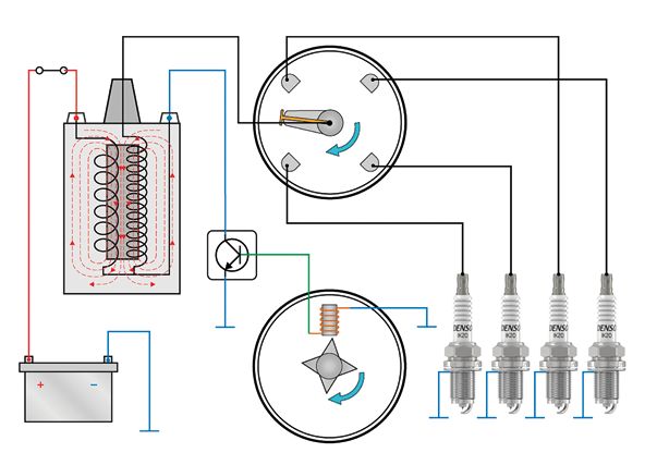
3. COIL IGNITION SYSTEM OPERATION
Using a changing or collapsing magnetic field to induce For ignition coils (and many types of electrical transformers), 3.4. Coil charge-up time and dwell period
an electric current the secondary winding is made with more windings than the primary
When a magnetic field has been created by applying an electric winding. When the magnetic field collapses, it will therefore induce
current to a coil of wire, any change in the electric current a higher voltage into the secondary winding compared to the voltage Time to build or charge-up the magnetic field operated contact breaker switch actually created a dwell time
(increase or decrease in current flow) then creates the same induced into the primary winding (Fig 3.6). When an electric current is applied to the primary winding of that reduced as the engine speed increased. Therefore at higher
change in the magnetic field. If the electric current is switched an ignition coil, it will take a short period of time for the current engine speeds, the reducing dwell time prevented the magnetic
off, the magnetic field will rapidly change; it will in fact collapse. The primary winding of an ignition coil can typically contain 150 flow to reach its maximum current (amperage). But because the field from building up to full strength.
The collapsing magnetic field will then induce an electric current to 300 turns of wire; but the secondary winding can typically contain strength of the magnetic field (or magnetic flux) created around
into the coil (Fig 3.4). 15,000 to 30,000 turns of wire, which is around 100 times greater the winding is directly proportional to the current flow, it will also The problem of short dwell times for mechanical ignition systems
than the primary winding. take the same amount of time for the magnetic field to reach its is explained in chapter 4.
maximum strength. When the current flow and magnetic field are
at their maximum, the magnetic field will then remain stable. Changing voltages affecting coil charge-up and dwell time
As with any electrical circuit, the current flow will change with
The time taken to build the magnetic field to maximum strength any changes in voltage. If the voltage supplied by the vehicle’s
is often referred to as the ‘charge-up’ time for the ignition coil. electrical system to the primary winding were to increase, this will
then increase the current flow through the primary winding. An
(1) If the electric current is not applied to the primary winding increase in current flow will then reduce the required charge-up
for long enough, the magnetic field will not reach its time for the magnetic field. However a decrease in voltage and
maximum strength. current flow will then increase the required charge-up time for the
magnetic field to reach full strength.
Primary Secondary (2) If the current is applied for too long, it could cause overheating
winding winding of the electrical circuits and the primary winding. Minor changes in voltage in the vehicle electrical system occur
regularly during normal driving; but a significant drop in voltage
The required charge-up times vary with different types of ignition coils but can occur during engine starting when the battery voltage can
If an electric current that is used to create a magnetic field is then are typically in the range of 4 milliseconds for older type ignition coils down reduce significantly. The low voltage will then significantly increase
switched off, the magnetic field collapses, which induces another to approximately 1.5 milliseconds for many modern types of coils. the required coil charge-up time; but with modern electronically
electric current into the coil of wire. controlled ignition systems, the dwell time is altered to compensate
The period when the ignition system applies an electric current for any increases or decreases in voltage.
to the ignition coil primary winding is often referred to as the
Fig 3.4 A collapsing magnetic field inducing an electric current
‘dwell period’ or ‘dwell time’. With modern ignition systems, Fig 3.7 shows the typical dwell time (in milliseconds) that would
into a coil of wire
the dwell period is controlled electronically so that there should be required at different battery voltages and engine speeds for
always be sufficient time to fully charge the coil. But for older type a modern ignition system.
In the same way that increasing the speed of movement of a mechanical ignition systems, the limitations of the mechanically
magnetic field across a coil of wire will increase the voltage induced
into the coil, if a collapsing magnetic field can be made to collapse
more rapidly, this will induce a higher voltage. Additionally, a higher
voltage can also be induced into the coil if the number of windings
in the coil is increased.
Mutual inductance and transformer action
If two coils of wire are placed adjacent to or around each other and The secondary winding in an ignition coil has more windings than
an electric current is used to create a magnetic field around one the primary winding. When the magnetic field collapses, the voltage
coil (which we can call the primary winding), the magnetic field will induced in the secondary will be greater than in the voltage induced
also surround the second coil (or secondary winding). When the in primary winding.
electric current is switched off and the magnetic field then changes
or collapses, it will induce a voltage into both the primary and the Fig 3.6 Voltage transformation in an ignition coil 16
secondary windings, which is known as ‘mutual inductance’ (Fig 3.5).
14
The magnetic field will initially be created by applying approximately
12-volts from the vehicle’s electrical system to the ignition coil 12
The magnetic field in primary winding. When a spark is required at a spark plug, the
the primary winding also ignition system will switch off the current flow to the primary
time (ms)
10
winding so that the current flow abruptly stops, which will cause
Dwell time (ms)
surrounds the adjacent
secondary winding. the magnetic field to collapse. The collapsing magnetic field will 8
7000
Collapsing the field then induce a voltage into the primary winding in the region of 200
Dwell
6000
induces electric currents Secondary volts; but the voltage induced into the secondary winding will be 6
Engine speed (RPM)
Engine speed (RPM)
5000
in both windings. winding approximately 100 times greater at around 20,000 volts.
4000
4
By using the effects of mutual inductance and by using a secondary 3520
winding that has 100 times more windings than the primary winding, 2 3000
Primary it is therefore possible to transform the original 12-volt supply into 2000
winding a very high voltage of approximately 20,000 volts. This process of 0 800
changing the low voltage into a high voltage can be referred to as 6 8 10 12 13 14 16 19
the ‘transformer action’.
Battery voltage
Battery voltage ( V ) (V)
In an ignition coil, the primary and secondary windings are wrapped
around an iron core, which helps to concentrate and enhance the strength
Fig 3.5. Mutual induction in adjacent coils of wire of the magnetic field and flux thus making the ignition coil more efficient. Fig 3.7 Dwell time provided by a modern ignition system depends on battery voltage and engine speed
10 11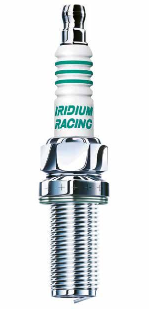
3. COIL IGNITION SYSTEM OPERATION
3.5. Ignition timing: providing the spark at the correct time Advancing ignition timing with increases in engine speed
If the engine speed is then increased from 1,500 RPM to 3,000 In theory, ignition timing would be advanced in direct proportion to the
RPM (Fig 3.10), assuming that the delay period remains constant increase in engine speed throughout the full engine speed range. But
The term ‘ignition timing’ is used to indicate when the spark is Allowing time for ignition lag, combustion and pressure rise at 2 milliseconds, the crankshaft will now rotate through a total of because engine and combustion efficiencies change with the changes in
produced at the spark plug. Ignition timing is usually quoted as The engine generally releases the maximum power when the 36° in 2 milliseconds (compared to 18° at 1,500 RPM). Therefore, engine speed, the amount of ignition timing advance generally reaches
the angle of crankshaft rotation before the piston reaches Top maximum pressure in the cylinder occurs at approximately 10° to achieve maximum cylinder pressure at 10° after TDC, the ignition a peak at around 3,000 to 4,000 RPM for most modern mass produced
Dead Centre (TDC) on the compression stroke. As an example, after TDC (when the piston has just started to move down the timing must now be advanced to 26° before TDC (compared to car engines.
the illustration in Fig 3.8 shows the position of the crankshaft and cylinder). However, the ignition timing must be set in advance 8° at 1,500 RPM).
piston if the ignition timing occurs at 20° before TDC. of when the maximum pressure is required because there are
delays between when the spark is provided and when maximum
cylinder pressure occurs.
The initial delay is due to ‘ignition lag’, which is a very brief period
between the spark occurring and the start of combustion of the Without combustion
air / fuel mixture. But it then takes time for the flame created at
initial combustion to spread or propagate throughout the rest of 1,500 RPM
the mixture, which will then combust and produce the heat to
expand the gasses. 3,000 RPM Maximum cylinder pressure
occurring approximately 10°
These delays between when the spark occurs and when maximum after Top Dead Centre
cylinder pressure is achieved can take in the region of 2 milliseconds.
The spark should be therefore provided approximately 2 milliseconds
before the maximum pressure is required.
The exact time between when the spark is provided and when maximum
cylinder pressure occurs varies depending engine operating conditions
and engine design. Combustion efficiency is generally better at mid-range
engine speeds, which reduces the total delay period, but changes in engine
load and air / fuel ratios as well as the use of exhaust gas recirculation also
affect the delay periods.
2 milliseconds
Fig 3.9 shows an example where maximum cylinder pressure is at 3,000 RPM
reached at 10° after TDC; but because of the delays for ignition
lag and flame propagation, the spark is provided 2 milliseconds 2 milliseconds
20° in advance. The crankshaft is rotating at 1,500 RPM, so the at 1,500 RPM
crankshaft will rotate through 18° during the 2 millisecond period.
Fig 3.8 Ignition timing occurring at 20° before Top Dead Centre The ignition timing (spark) is therefore set at 8° before TDC.
(TDC)
-60 -50 -40 -30 -20 -10 TDC 10 20 30 40 50 60
% of fuel burnt
Maximum cylinder pressure Fig 3.10 Ignition timing advance at 1,500 and 3,000 RPM
occurring approximately 10°
after Top Dead Centre
DENSO Highlight
DENSO Spark Plugs: reducing the to ensure that ignition timing and combustion
inconsistencies of ignition lag do not occur too early.
Pressure DENSO Spark Plug technologies include the use
The delay time for the ignition lag period can be
without of fine-electrode spark plugs (patented 0.4 mm
combustion inconsistent and can vary from one combustion
diameter) that help to reduce the inconsistencies
cycle to the next. These inconsistencies will then
2 milliseconds of ignition lag; and this then allows engine
shorten or lengthen the whole combustion process,
manufacturers to build in smaller safety margins
which will advance or retard the exact time that the
for the ignition timing so that the ignition timing
maximum cylinder pressure occurs.
can be closer to the optimum setting, which
Engine manufacturers must therefore provide a improves combustion and engine efficiency.
-60 -50 -40 -30 -20 -10 TDC 10 20 30 40 50 60
safety margin for the ignition timing calculations
Fig 3.9 Setting ignition timing approximately 2 milliseconds before maximum cylinder pressure is required
12 13
3. COIL IGNITION SYSTEM OPERATION

  Ignition timing dependent on engine load                                   Combustion knock sensing
  Although the optimal ignition timing is initially dependent                Many modern engines are also equipped with an additional sensor
  on engine speed, the timing is also changed with changes                   known as a ‘knock sensor’ or other knock sensing equipment.
  in engine load.                                                            Minor changes can occur in the engine operation conditions that
                                                                             are not immediately detectable using the other sensors; but if the
 When an engine is operating at light load conditions, which will            knock sensor detects any momentary or prolonged combustion
 usually mean that the throttle is only partially open, there will be        knock, it passes this information to the engine management ECU.
 a reduced mass of air entering the cylinder; therefore cylinder             The ECU can then slightly retard the ignition timing until the knock
 pressures will be lower than for full load conditions. Additionally,        is no longer present.
 for older type engines and also on some modern engines, to help
 with economy and emissions, the air / fuel ratio can be leaner (less        For those engines that were not equipped with all of the modern
 petrol / gasoline mixed with the air). The lower cylinder pressures         type sensors, the ignition computer was programmed with a
 and lean mixtures take longer to combust, which therefore requires          pre-defined ignition map that might only embrace engine speed
 the ignition timing to be advanced further to allow more time for           and load. However, to ensure that the ignition timing did not
 combustion and to ensure that the maximum cylinder pressure still           become over-advanced or retarded during critical operating
 occurs at around 10° after TDC.                                             conditions a safety margin would be included in the pre-defined
                                                                             timing map that might for example very slightly retard the ignition
 During light load conditions, the EGR system (exhaust gas recirculation     timing to prevent combustion knock.
 system) can divert significant amounts of inert exhaust gas into the
 cylinder to help reduce combustion temperatures and harmful emissions.      Effects of advanced or retarded timing
 The use of EGR (see section 5.5) slows down the combustion process,         For most engines and operating conditions, the ignition timing will                                                                                      If the spark occurs too late (retarded ignition timing), the pressure
 which will again require an advance in the ignition timing.                 occur in a range of just a few degrees before TDC at low engine            If the spark occurs too soon (advanced ignition timing) the cylinder          rise will also occur too late. The piston could have already moved
                                                                             speeds to around 30° or more before TDC at higher engine speeds.           pressure will increase too early whilst the piston is still rising on         down the cylinder on the next stroke; and the pressure rise caused
 Other operating conditions affecting ignition timing                        However, with older engines that were generally less efficient and         the compression stroke. The early increase in cylinder pressure can           by combustion will therefore have a much reduced effect on pushing
 For older vehicles equipped with mechanical type ignition systems           had less efficient combustion chamber designs, the timing could            create engine knock.                                                          the piston down the cylinder.
 (see section 4.1), optimal timing was usually dependent on just             often occur as much as 45° before TDC.
 engine speed and load. However, modern electronically controlled                                                                                       Fig 3.11 Advanced ignition timing                                             Fig 3.12 Retarded ignition timing
 ignition systems (that usually form part of engine management               For some engine designs and with some operating conditions (that were
 systems) alter the ignition timing depending on many engine                 usually emissions related), the ignition timing could be just after TDC.
 operating conditions that include: engine speed, engine load,
 coolant temperature, air temperature, air / fuel ratio, throttle opening,   (1) Optimal ignition timing. Optimal ignition timing is essential
 fuel quality and EGR rate.                                                       for efficient combustion, which will then lead to good engine                   Without combustion
                                                                                  performance, economy and cleaner emissions.
     The different operating conditions are detected by various                                                                                                   Retarded timing            Engine knock
     sensors that pass the operating information via electronic              (2) A
                                                                                  dvanced or early ignition timing. Ignite the air / fuel mixture                                           or detonation
     signals to the engine management computer. The computer                     too early and the cylinder pressure and temperature will                         Optimal timing
     then monitors the signals and provides the optimized ignition               increase too soon. The pressure and temperature can become
     timing based on the information provided by the sensors.                    too high and create engine knock, especially if a significant                    Advanced timing
                                                                                 part of the pressure rise occurs whilst the piston is still moving
                                                                                 up the cylinder on the compression stroke (Fig 3.11).                            Too advanced

                                                                             (3) Retarded or late ignition timing. Ignite too late and the
                                                                                  pressure rise caused by combustion will occur too late.
                                                                                  The piston will have already moved down the cylinder
                                                                                  further than during normal operation, therefore the force
                                                                                 of the pressure rise pushing the piston down the cylinder
                                                                                 will be reduced and less power will be developed (Fig 3.12).

                                                                             Fig 3.13 shows a comparison of the effects of advanced, retarded
                                                                             and optimal ignition timing.

                                                                                                                                                            -60          -50        -40        -30        -20         -10       TDC       10          20         30          40         50         60

                                                                                                                                                        Fig 3.13 Comparison of advanced, retarded and optimal ignition timing

14                                                                                                                                                                                                                                                                                                            15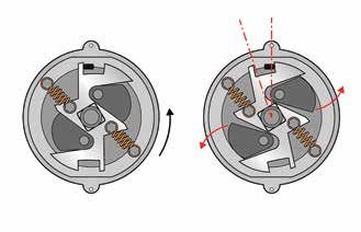
4. M
ECHANICAL AND ELECTRONIC
4.1. Basic mechanical ignition system 16
4.2. Early type electronic ignition systems 20
4.3. Modern electronic ignition systems 21
IGNITION SYSTEMS
4.1. Basic mechanical ignition system A spring that forms part of the contact breaker assembly holds the Capacitor / condenser in the primary circuit
switch in the closed position, which allows the electric current to When the contact breaker switch opens, the collapsing magnetic
flow through the coil primary winding. The current flow then creates field can induce an electric current with a voltage of approximately
Mechanical switching of the primary circuit First phase of operation: coil charge-up / dwell period a magnetic field around the primary and the secondary windings. 150 to 200 volts into the primary winding. This current will try to
Fig 4.1 shows the main components of a mechanical ignition system, Fig 4.2 shows the first phase of operation for the mechanically jump across the open contact breaker switch and create an electric
which is based on the principles of the Kettering ignition system. operated system. For convenience, Fig 4.2 shows the ignition coil secondary winding located arc that would quickly erode away the contact faces of the switch.
adjacent to the primary winding, but in fact, coils the primary and secondary But this induced current would also have the effect of maintaining
The battery provides a 12-volt power supply to the ignition The battery provides a 12-volt power supply to the ignition coil windings are both wrapped around the iron core. the magnetic field around the primary and secondary windings thus
coil via the ignition switch. The power supply passes through via the ignition switch. The power supply passes through the coil preventing the magnetic field from rapidly collapsing, which would
the coil primary winding and through to ground via a ‘contact primary winding and through to ground via a ‘contact breaker’ switch. Second phase of operation: discharge of high voltage prevent the high voltage being induced into the secondary winding.
breaker’ switch. A series of cam-lobes (one for each cylinder) are attached to a rotor
shaft located within the distributor body (Fig 4.3). The rotor shaft A capacitor is therefore connected to the primary circuit so that
is connected to the camshaft, rotating at half the engine speed. the induced voltage is effectively absorbed into and stored within
The rotating cam-lobes force the contact breaker switch to open the capacitor. When the contact breaker switch then closes again
Distributor at the appropriate time, which immediately breaks the current flow (to once again allow current to flow through the primary winding),
through the coil primary winding. The magnetic field will then very the capacitor can then discharge the stored electrical energy
rapidly collapse across both the primary and secondary windings, back into the primary circuit, which helps to create the next
which induces a high voltage into the secondary winding. magnetic field.
Ignition switch The high voltage then passes through an insulated wire to the
rotor arm located inside the distributor cap. Because the rotor arm
is also rotating on the rotor shaft, it can direct the high voltage
in sequence to the four contacts in the distributor cap. The high
Battery Spark plug voltage then passes to the spark plugs via insulated wires.
Ignition coil Contact breaker
Fig 4.1 Mechanical ignition system main components
2. T
he magnetic field is collapsing 3. H
igh voltage delivered by the 4. The rotor arm has rotated so that the high
Magnetic field created around the Rotor arm: distributes the high voltage to the and inducing the high voltage ignition coil secondary winding voltage is directed to cylinder -1 spark plug
primary and secondary windings, appropriate spark plug in the firing sequence into secondary winding
and around the iron core
Ignition switch (in the on position)
Ignition coil
primary winding
Contact breaker switch held
in closed position by a spring
Iron core 1. A
cam-lobe on the rotor
has opened the contact
breaker switch
Ignition coil
Battery secondary winding Rotator shaft with 4 cam-lobes. Each cam-lobe opens
Capacitor the contact breaker switch for each of the 4 cylinders Battery
Fig 4.2 Basic mechanical ignition system operation. Phase-1 dwell period creating the magnetic field Fig 4.3 Basic mechanical ignition system operation. Phase-2 discharge of high voltage to create the spark
16 174. MECHANICAL AND ELECTRONIC IGNITION SYSTEMS
Ignition timing advance / retard mechanisms Limitations of mechanical timing systems
It is explained in chapter 3 that the ignition timing must change The accuracy of the ignition timing on mechanical ignition 60° dwell angle 40° dwell angle
with changes in engine speed and load. systems is limited to the capabilities of the hardware. Fine-tuning, (contact breaker switch closed) (contact breaker switch closed)
adjustments and component replacements were often required
For mechanical ignition systems, advancing the timing with as part of a routine maintenance schedule. As an example of the
increases in engine speed was achieved using pivoted weights limitations, Fig 4.6 shows a typical engine speed related timing
and springs (Fig 4.4). The weights are mounted on a plate that advance graph for a mechanical ignition system compared to
is attached to the rotor shaft assembly; therefore the weights the ideal timing requirement.
and plate rotate with the shaft. As the engine speed increases,
the effects of centrifugal force push the weights outwards against
the tension of small springs. The movement of the weights
then advances the rotation of the cam-lobes on the rotor shaft,
which causes the opening of the contact breaker switch to also
advance thus advancing the ignition timing. Ideal ignition timing
Degrees
of
Pivoted timing 90° between 60° between
weights advance cam-lobes cam-lobes
Timing provided by centrifugal
advance mechanism
Fig 4.7 Dwell angle shown as 60° of distributor shaft rotation Fig 4.8 Dwell angle shown as 40° of distributor shaft rotation
for a 6-cylinder engine
Idle speed Maximum Maximum
torque engine
speed speed When the engine is then rotating at 5,000 RPM, the same 60° of Different solutions were used on the mechanical ignition
distributor shaft rotation will only take 4 milliseconds, which is systems to overcome the problem of reducing dwell time.
Fig 4.6 Limitations of centrifugal advance mechanism exactly the right amount of time to charge the coil with a maximum One solution was to use a more powerful ignition coil. Another
Return spring strength magnetic field. But if the engine were to rotate any faster, extreme solution that was used for high revving engines with
there would be insufficient time to fully charge the ignition coil, 8 or 12 cylinders was to fit two separate distributors each with
Fig 4.4 Speed related mechanical timing advance mechanism Due to the use of progressive return springs (Fig 4.4), the timing which would result in reduced energy in the magnetic field and their own ignition coil. The engines therefore effectively had two
advance provided by the centrifugal system increases in two linear reduced voltage being delivered to the spark plugs. separate ignition systems that delivered the high voltage to the
steps. However the ideal timing advance changes in a non-linear spark plugs for half of the engine’s cylinders.
A second mechanism is then used to alter the ignition timing with progression. To ensure that the timing is never over advanced, the The problem of a reducing dwell time when the engine speed
the changes in engine load (Fig 4.5). The contact breaker switch centrifugal timing must be set so that the ignition timing is always increases will be more significant for engines with more cylinders.
is mounted on a base plate that can rotate slightly clockwise or slightly retarded from the ideal value. For example, on a 6 cylinder engine, there will be 6 cam-lobes,
anti-clockwise. The base plate is then connected to a diaphragm with only 60° between each lobe (Fig 4.8) and only 40° for the
capsule that receives intake manifold pressure via a tube. Dwell period / dwell angle dwell angle. The result will be that at an engine speed of 5,000
On a mechanical ignition system the dwell period starts when the RPM, the 40° of dwell angle will only last for 2.6 milliseconds.
When the intake manifold pressure changes with the changes rotating cam-lobes allow the contact breaker switch to close so If the coil requires 4 milliseconds to fully charge, so the dwell
in engine load, the diaphragm moves and causes the base plate that current then flows through the coil primary winding. The dwell time will be much too short, which will result in a lower voltage
and contact breaker switch to rotate slightly. The rotation of period then stops when one of the cam-lobes forces the contact and may lead to misfires.
the baseplate and switch then alters the ignition timing with the breaker switch to open again, which switches off the current flow
changes in engine load. to the primary winding. The dwell period can therefore be specified
as the angle of rotation of the cam-lobes whilst the contact breaker
switch is in the closed position. DENSO HIGHLIGHT
Spring Contact breaker Fig 4.7 shows 4 cam-lobes (for a 4 cylinder engine), which means
switch base plate there will be 90° between the same points of adjacent cam-lobes. The mechanical system helps us understand the development
The shape of the cam-lobes in the example allows the contact
breaker switch to remain closed for 60° of rotation. Therefore, there of the current digital ignition systems.
is a dwell angle of 60 distributor degrees when the contact breaker
Di
switch is closed and current flows through the coil primary winding.
rec
The one critical part of the ignition system that has never been replaced,
tion
If, as an example, a crankshaft is rotating at 1,000 RPM, and probably never will, is the spark plug.
on c a m
the distributor rotor (which rotates at half engine speed) will
rotate at 500 RPM. At this speed, it will take 20 milliseconds It is critical that the spark plug provides high performance and precisely timed
mo
for the distributor shaft to rotate through the 60° of dwell angle,
ignition. DENSO understands high quality is required to meet these demands
ti
on
but because the ignition coil only requires approximately 4
milliseconds of charge-up time, there is more than sufficient from engine manufacturers. To achieve this, DENSO combines the best and
Connection to intake dwell time for the magnetic field to build up in the coil.
proven quality systems with years of experience.
manifold pressure
Fig 4.5 Engine load related mechanical timing advance
18 19You can also read