Experimental Investigation of Stability and Structure of Vertical LPG Inverse Diffusion Flames Issuing from an Elliptic Burner
←
→
Page content transcription
If your browser does not render page correctly, please read the page content below
Adel Mohamed Hussien / Engineering Research Journal 171 (September 2021) M33- M50

 Experimental Investigation of Stability and Structure of
 Vertical LPG Inverse Diffusion Flames Issuing from an
 Elliptic Burner
 A. A. Mahgoub*, A. M. Hussien and K. A. Emara

Department of Mechanical Power Engineering, Faculty of Engineering at El-Mataria,
 Helwan University, Massaken El-Helmia, P.O. 11718, Cairo, Egypt.

 *Corresponding author: Ahmed_mahgoub93@m-eng.helwan.edu.eg

Abstract
The present paper experimentally examines the influence of the progressive
variations of the central air jet velocity in a concentric circular-elliptical inverse
diffusion flame (IDF) on the visual and thermal structure and stability of the
developed flames. All experiments are conducted at a fixed fuel flow rate (liquefied
petroleum gas) throughput that emerges from the annular elliptic passage having an
aspect ratio of 2:1. The visual images are aided via a digital camera and
shadowgraphs, while the thermal structure (axial and radial temperature profiles) is
acquired using a bare fine wire (125 µm) thermocouple; rendering radiation loss
insignificant. The visual images and shadowgraphs clearly indicate the existence of
four regimes: (i) an annular partially premixed region at the burner rim, (ii) an inner
central premixed blue flame, (iii) an outer luminous yellowish post combustion zone
and (iv) the flame tip buoyant zone. The progressive increases of the central average
air velocity ( ̅ = 7.4 m/s up to 31.3 m/s) result in shortening the visible flame length
and narrowing the flame width. These are coupled with changing the flame
appearance from a yellowish diffusion flame with a sooty core regime to an intense
central premixed flame surrounded by a soot ring to blue flames exhibiting intense
central radiation regime associated with soot oxidation. At extremely high air velocity
> 21 m/s, locals flame extinction and re-ignition occurs at the boundaries of the ellipse
minor axis and further increase of ̅ causes complete extinction of the main flame.
These findings are very much supported by the mean gas temperature measurements
that indicate steep temperature rise associated with the formation of a central
premixed combustion within the flame core which is followed by the diffusion mode
of combustion. A plateau of the axial temperature profiles is observed in the transition
zone between the two regions whereby the rise in temperature due to soot oxidation
is balanced by the radiation loss.
Keywords: Inverse diffusion flame, Elliptic burner, Liquefied petroleum gas, Flame
structure, Flame stability
 M33
Adel Mohamed Hussien / Engineering Research Journal 171 (September 2021) M33- M50

Nomenclature
Lf Visible flame length measured from burner exit to flame tip [mm]
 ̅ Averaged velocity of the central air jet [m/s]
 ̅ Averaged velocity of the fuel jet [m/s]
y Height vertical distance measured from burner exit [mm]

1 Introduction
Diffusion (non-premixed) flame represents one of the most common flame
configurations in the combustion systems. The inverse diffusion flame (IDF) is a distinct
sort of diffusion flames, which varies from the ordinary diffusion flame in the relative
position of air and fuel jets. In the IDF, a central air jet is surrounded by an outside fuel
jet, and the fuel is entrained inward by the high-velocity jet of air and merges with the
air to form a partially premixed flame. Otherwise, it could burn mainly in the diffusion
mode. The normal diffusion flame has a broad flammability limit. While the premixed
flame has the characteristics of low formation of soot. Inverse diffusion flame exhibits
the characteristics of both premixed and non-premixed (diffusion) flames, hence, can
exploit the advantages of both flames in term of stability limit improvement, lower
pollutants, and operating safety. The IDF is cleaner than normal diffusion flame and is
improbable to the lift off and flash back phenomena when compared to a premixed
flame. Consequently, the feasibility of utilizing IDFs in domestic and industrial heating
applications is of interest, [1–5].
The flame stability investigation is a key issue in any combustion research. The study
of flame stability is essential to understand the operating range of the combustor. The
flame stability of a laminar inverse diffusion flame was investigated in a previous study.
It identified six different types of flames at a wide range of fuel and air velocities with
a double concentric tube, Ref.[6]. Other studies reported the flame stability limits of
turbulent IDFs for different burner configurations and different fuels, [3], [7]–[10]. The
turbulent flame stability limits of a recessed and back step Co-axial burners was
examined and it was observed that the back step burner flame has a lower flame stability
limit than the coaxial IDF, [8]. An experimental study investigated the flame structure
of a methane IDF and its dependence on central air and coaxial fuel velocities using OH-
Planer laser–induced fluorescence (OH-PLIF) technique. Its OH measurements
indicated local extinction occurrence, especially at the higher air-fuel velocity ratio, [9].
Another study introduced the stability limits and near blowout characteristics of
unrecessed and recessed compressed natural gas (CNG) inverse jet flames by varying
air jet velocity at a constant fuel jet velocity. The results revealed that unrecessed flames
have higher flame stability as compared to the recessed flames for the same fuel jet
velocity, [10].
Numerous previous studies have already been performed to understand IDFs
characteristics. The length of laminar IDF proportionally increases with the air flow rate,
[11],[12]. The diameter of the nozzle and the flow rate of air and fuel also affect the
structure, thermal characteristics, and flame length of IDF, [13]. The air-fuel ratio also
has effects on the flame appearance and centerline temperature distribution,[14]. The

 M34
Adel Mohamed Hussien / Engineering Research Journal 171 (September 2021) M33- M50

effect of various air/fuel velocity ratio at a fixed fuel flow rate on the flame structure
was studied to realize the role of mixing and entrainment in IDF, [9],[15]. The effect of
burner configuration influences the thermal structure of the IDFs because of the mixing
quality between fuel and air, [5]. Also, the diameter of the airport influences the
characteristics the heat transfer of IDFs, [16]. The effects of Reynolds number and
equivalence ratios on centerline temperature, flame shape and CO emissions are also
reported, [17]. The characteristics of the swirl-stabilized IDF including heat transfer,
flame appearance, and emissions are reported in, [1], [2], [18]. Other studies investigated
the characteristics of the IDF experimentally as well as numerically, they investigated
the flame appearance, centerline temperature distribution, and the flame length, [19],
[20].
Some previous studies investigated the effect of burner tubes’ shapes either circular or
elliptical. The effects of elliptic and circle burner geometries on stability and global
emission characteristics of premixed and partially premixed flames were reported in
[21],[22]. They found that the elliptical burner geometry reduced the blowout stability.
The premixed flames of elliptic burners characterize lower liftoff velocity, shorter, and
lower heat radiation to the surrounding as compared to circular burner flames. Also, they
produce higher peak in-flame temperatures and produced less peak NO as compared to
circular burner, [23].
The concentric elliptic burners have also undergone several investigations with co- and
cross-flow streams. The effect of elliptic burner orientation with respect to co-flow pipe
on the stability limits and global emissions of diffusion flames were reported in [24]. It
was found that elliptic burner diffusion flames when properly employed in elliptic co-
flow could reduce certain pollutants. Jet diffusion flames of another concentric elliptic
burner with co- and cross-flow streams were examined in [25]. Shadow graphic imaging
using ultraviolet laser was performed on non-premixed flame issuing from concentric
elliptic burner, [26].
The demand for utilizing sustainable fuel sources in power generation and thermal
processes has increased with the concern of the limited resources of petroleum-based
fuels and greenhouse gases emissions. Liquefied petroleum gas (LPG) is considered in
many research as one of the major future energy resources due to its wide availability
[27], [28]. LPG characterizes clean, relatively low cost and abundant energy source,
which drives the research to study its combustion characteristics to improve the prime
movers efficiencies with reducing the NO x emissions, [28].
From the previous literature overview, it is found that the effect of elliptical burner shape
on IDF characteristics was not well covered. So, the current study discusses the stability
limits and structure of IDFs issuing from a concentric circular-elliptic burner. The effect
of varying the central air velocity with constant fuel velocity on flame characteristics
will be discussed. The study includes visual and shadowgraph imaging and inflame
temperature measurements to investigate the flame structure. The flame images at
different operating conditions are compared and analyzed. The analyses are focused on
providing the associated variations in visible flame length, and shadowgraph imaging to
show the details of different flame zones. The changes of axial and radial flame
temperature inside the flame regimes are measured and analyzed for selected cases.

 M35
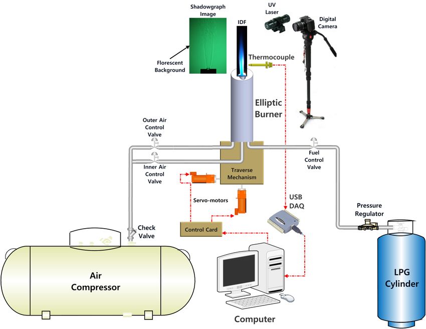
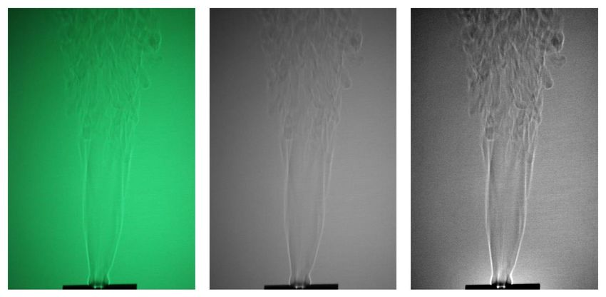
Adel Mohamed Hussien / Engineering Research Journal 171 (September 2021) M33- M50

2 Experimental Setup, Facilities, and Program
Figure (1) depicts the schematic diagram of the experimental setup, which contains the
following:
2.1 Burner test-rig
The elliptic vertical burner shown in Figure (2) comprises of three concentric coaxial
vertical tubes of stainless steel having a length of 300mm each. The central round tube
has an inner diameter of 8mm. The inner elliptic tube has major and minor axes of 30mm
and 15mm, respectively (Aspect ratio 2:1). The outer elliptic tube has major and minor
axes of 70mm and 35mm, respectively (Aspect ratio 2:1). Fuel (LPG) exits through the
inner elliptic tube and the air (central air) exits through the central round tube. The outer
air of the outer elliptic tube is turned off in the current study. The assembly of the burner
can be traversed in the horizontal and vertical directions. The movements are
implemented by linear DC motors to scan the flame radially and axially. The movements
are controlled by a software (LabVIEW) with a resolution of up to ± 0.05 mm. The test
rig is housed inside a rectangle room having side glass walls to further prevent the effects
of any natural drafts. The present experimental program for the whole investigated cases
is summarized in Table (1).The fuel flow rate is adjusted at a fixed value of 0.4 l/min
and the total flow rate of the central air is varied from 40 to 54 l/min. The fuel used is
liquefied petroleum gas (LPG) composed of 70% Butane C4H10 and 30% Propane C3H8,
[28]. The fuel flow rate is electronically controlled by an ON/OFF solenoid valve
through Lab VIEW program and measured by a calibrated ball rotameter having a full
scale of 4 l/min. The air is supplied from air compressor. The air pressure from the
compressor is regulated by pressure regulator. The central airflow rate is controlled by
a needle valve and measured by orifice meter with a U-tube manometer.
2.2 Measuring systems
2.2.1 Flame visualization system
A digital camera having a high resolution of 30.3 Megapixels is employed to obtain
accurate, highly resolved, and colorful visual images of the flames under different
operating conditions. These images allow obtaining both the visual flame length as well
as identifying the different flame regimes.
2.2.2 Shadowgraph imaging system
The shadowgraph imaging of the investigated flames is obtained to differentiate between
the flame zones. A low power 20-mW compact continuous wave (CW) 405 nm laser
diode is used to backlight in order to generate a large flow field shadowgraph on a distant
florescent screen. The florescent screen is made of a standard fluorescent sticker that
appears pale under the illumination of burner flames but glows under ultraviolet and
blue laser radiation (300-420 nm). A digital camera is used to image the flame shadows.
The acquired images undergo processing sequence (a to c) to improve their quality and
to clear their details, see Figure (3). Mathematica 12.1 software was used to process and
analyze the acquired images.

 M36
Adel Mohamed Hussien / Engineering Research Journal 171 (September 2021) M33- M50

 Figure (1) Schematic diagram of the experiment set-up.

 Figure (2) Elliptic burner details.
 M37
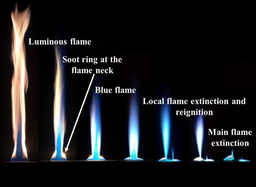
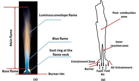
Adel Mohamed Hussien / Engineering Research Journal 171 (September 2021) M33- M50

Table (1) Experimental program.
 Measurements
 Run ̅ [m/s] ̅ [m/s] Visual Shadowgraph In-Flame
 Imaging Imaging Temperature
 A 0.026 13.26 √ √ Axial
 B 0.026 14.42 √ √ Axial
 C 0.026 15.58 √ √ Axial & Radial
 D 0.026 16.74 √ √ Axial
 E 0.026 17.90 √ √ Axial

 (a) (b) (c)
 Figure (3) Image processing sequence for shadowgraph imaging, (a) raw image, (b)
 gray-scale image, and (c) sharpen image.
2.2.3 In-flame temperature measurement
Mean in-flame temperature was obtained by a 125μm platinum/platinum 10% Rhodium
(type-S) wire thermocouple. The signal of the thermocouple is digitized by the usage of
the Omega USB reader and its interface software by connecting to the PC. Radiation
corrections were performed as in, [29], assuming a thermocouple emissivity of 0.2. The
radiation corrections never exceed 30°C, giving further support to the previous findings
that radiation loss could be ignored for fine wire thermocouples,[30].

3 Results and Discussion
3.1 IDF structure
All IDFs comprise base and main flames (dual structure) as depicted in Figure (4-a).
The base flame is two crescent-shaped lower parts of the IDF between the flame neck
and the burner exit, also known as the entrainment zone, where the fuel is entrained
towards the central air jet, as depicted in Figure (4-b). At the flame base, a portion of
the fuel burns in diffusion mode, and the other portion is entrained into the central air
jet to burn premixed mode. The base flame is serving as a pilot flame, which heats the
incoming reactants to stabilize the main flame. The main flame is the upper part of the
IDF ensuing from the neck of the flame and contains the post- combustion zone and the
inner reaction zone (blue zone), as depicted in Figure (4-b). The base and main flames
are separated by a flame neck region with a yellow soot ring surrounds the flame neck
[3]. The IDFs have unique flame characteristics including a base flame that is absent in

 M38
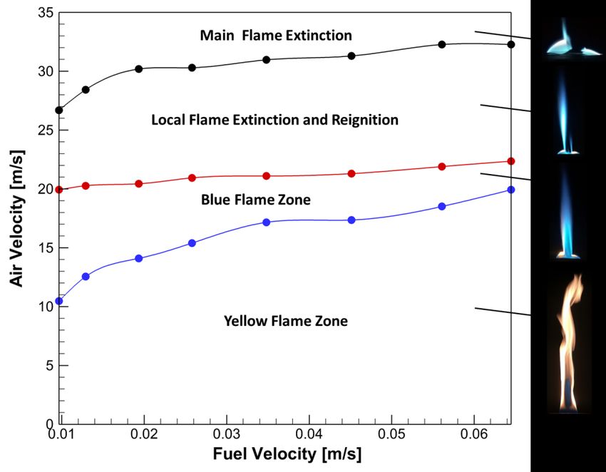
Adel Mohamed Hussien / Engineering Research Journal 171 (September 2021) M33- M50

NDF configurations. Moreover, the central airflow rate is in the turbulent regime and
the fuel flow rate is in the laminar regime, [3], [20].

 Figure (4) (a) Image of IDF appearance and (b) Schematic structure of IDF flame
3.2 Flame stability
The flame stability of IDFs is an essential parameter used to determine the range of
operating conditions that can sustain a stable flame. A flame is considered stable if it
was free of main flame local extinctions and it worth mention that there is no total flame
blow-off for the current burner configuration. The flame stability in the current study of
the LPG IDFs for the elliptic burner is investigated by varying the airflow rate at a fixed
fuel flow rate. The following sections include analysis of the appearance and stability
characteristics of LPG IDFs of the elliptic burner over a wide limit of operating
conditions.
3.2.1 Flame appearance
As depicted in Figure (5), the effect of the central air jet velocity at constant fuel flow
velocity of 0.026m/s on the visual flame appearance is examined. It is important to
obtain a change in the overall equivalence ratio with maintaining a fixed thermal input.
At the lower central air jet velocity ( ̅ =7.4m/s), the flame has a similar appearance to a
pure normal diffusion flame. The fuel burns with the air entrained from its surroundings,
and the flame is highly luminous due to the soot incandescence. For a certain range of
air velocity ( ̅ =11.7-17.9 m/s), an IDF is established inside an ordinary diffusion flame.
Similar flames were observed and reported in previous studies, [4], [13]. The IDF with
lower blue zone enveloped by a luminous zone is observed in Figure (5b) for a central
air velocity ( ̅ =11.7 m/s). The blue flame with a soot ring at the neck of the flame is
observed in Figure (5b-d) for a central air velocity range ( ̅ =18.6-17.6 m/s), and the
main flame becomes non-luminous because of improvement of partial premixing
between air and fuel caused by air momentum increasing. Also, the soot ring decreases
with increasing the air velocity due to combustion enhancement.
With increasing the air jet velocity ( ̅ =21.9-26.4 m/s), the main flame faces local
extinctions and re-ignitions (flame tearing) as observed in Figure (5e-f). This is caused
by an increasing in the strain rate. The strain rate parameter is determined by ( ̅ – ̅ )

 M39
Adel Mohamed Hussien / Engineering Research Journal 171 (September 2021) M33- M50

/D, where D is the diameter of central air pipe. With increasing the air velocity ( ̅ >31.3
m/s), higher strain rate occurs at the air and fuel streams interface, which can cause the
intense interaction of the vortical structure in the shear layer with the main flame, [7].
This leads to the disappear of the re-ignition phenomenon, which leads to main flame
extinction as observed in Figure (5g).

 ̅ at a constant fuel
 Figure (5) The flame appearance with increasing air velocity
 ̅
 velocity = 0.026 m/s.
3.2.2 Flame stability characteristics
The flame stability mapping was implemented by varying air velocity with constant fuel
velocity as depicted in Figure (6). The flame stability regions comprise of yellow flame,
blue flame, local flame extinction and re-ignition, and main flame extinction. For the
current burner configuration, the operating conditions at very low air velocity led to
normal diffusion flames. The IDF with lower blue zone enveloped by luminous zone
appears at the upper region of the yellow flame zone. The blue flame zone lies above
the yellow flame zone up to the air velocity value of 22m/s. Because of the enhanced
mixing among fuel and air, the flames become momentum dominated instead of
diffusion dominated that makes the flames blue.
The almost-constant air velocity value of 22m/s forms a strain rate limit for the stable
blue flames in conjunction with the fuel properties (i.e., burning velocity). With air
velocity higher than 22m/s, the local extinction and re-ignition zone begins. With
increasing air velocity, the interaction of the main flame with shear layer vortices can
result in the greater flame stretch which can perform to main flame extinction. The main
flame extinguishes from the neck of the flame while the base flame remains attached to
the burner edge. The main flame extinction zone occurs for air velocity higher than
32m/s. The main flame extinction limit increases slowly up to a constant fuel velocity
of 0.056 m/s. It is important to observe that the main flame extinction limit keeps almost
unchanged for the fuel velocity range of 0.056-0.064 m/s. The main flame extinction
occurs because of high strain rates at the interface of the base and main flames
accompanied by high rates of heat dissipation due to the high core momentum, [7].
Moreover, the equivalence ratio of the mixture at the main flame decreases significantly
with an increase in the strain rate due to ambient air entrainment,[7]. It is remarkable to
note that the flame lift-off phenomenon is absent because the base flame stabilizes and
 M40
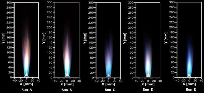
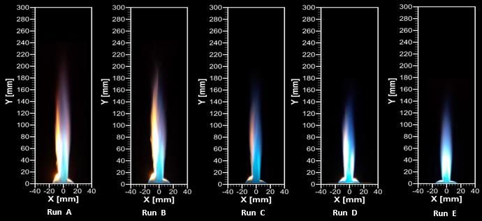
Adel Mohamed Hussien / Engineering Research Journal 171 (September 2021) M33- M50

anchors the main flame to the rim of the burner. This is due to the base flame is stabilized
with the surrounding air like a normal diffusion flame.

 Figure (6) Flame stability map for the current burner configuration.
3.3 Varying central air velocity at constant thermal input
3.3.1 Flame appearances
The appearance of the flames helps in understanding the physical processes involved in
the IDF combustion. The IDF's appearance relies on the burner configuration, the air
velocity jet, and the fuel velocity. The IDF images with increasing air jet velocity,
 ̅ =13.26 to 17.9 m/s at fixed fuel velocity ̅ =0.026 m/s for major and minor axes are
shown in Figure (7) and Figure (8). The enhanced mixing between air and fuel jets with
increasing the air velocity is evident of an absent luminous zone. Moreover, the flame
is observed to become thinner with air velocity increase. Due to the fuel is introduced
through an elliptical tube around the circular air jet, a non-homogenous fuel distribution
through the entraining air jet is existing. This leads to reshaping the flame on both major
and minor axes of the elliptic fuel tube.
For Runs A and B, the blue zone enclosed by a luminous zone of the IDF was previously
mentioned by Wu and Essenhigh, [6]. The formation of the luminous zone is due to the
low air jet momentum, which reduces the effectiveness of fuel-air mixing. The increase
in the velocity of the central air jet reduces the flame luminosity in the upper portion of
IDF as observed in (Run C). The reduced flame luminosity with an increase in air jet
velocity is an indication of reduced soot formation. It is evident that the soot ring at the
top of the flame base in IDF refers to soot formation, which is attributed to the non-
premixed combustion of the fuel. With increasing the air velocity, both the luminous
zone and the soot ring decrease (Run D and E). The higher entrainment of the annular
fuel jet by the central air jet enhances the air-fuel mixing that imparts a partially
premixed structure to the IDF. It can be noted that with increasing the central air jet

 M41
Adel Mohamed Hussien / Engineering Research Journal 171 (September 2021) M33- M50

velocity, the length of the IDF is reduced, as shown in Figure (7) and Figure (8). It
should be noted that for a fixed fuel jet velocity, the IDF main flame becomes locally
lean with an increase in air jet velocity. Also, the main flame entrains more air from the
ambient, that can create its local equivalence ratio further leaner.
In a pure normal diffusion flame, the fuel is burned with an entrained air from the
surrounding; thus, the flame is yellow. In IDFs, the central air jet drags the fuel jet. The
degree of fuel entrainment by the air jet determines the degree to that the fuel is burned
in the premixed mode or diffusion mode. Change in the color of the IDF is an indication
of the effect of the entrainment of the fuel jet. It can be observed that the increasing air
velocity jet enhances the entrainment of the fuel jet, which, performs to more fuel burnt
in the premixed mode, [2]. The same influences of air jet velocity on color and flame
length have been reported in, [2],[5]. Finally, at higher air jet velocity, stronger
entrainment and turbulence aid mixing among fuel and air, so that the flame becomes
more intense and shorter.
3.3.2 Visible flame length
In addition to the flame appearance, the visible length of the flame is a significant feature
of the IDFs. The visible flame length is an important parameter to describe IDFs, which
aid in estimating the range of mixing in air/fuel jets and it is an indication for the
residence time. It is a significant to relate the visible flame length with dominant
parameters such as exit tube diameters and air/fuel jet velocities, which will be helpful
in designing practical combustion processes. The visible flame length is defined as the
summation of the base flame and main flame lengths.
In the present study, the visible flame length of LPG IDFs is investigated by varying the
central air jet velocities at a constant fuel jet velocity, ̅ = 0.026m/s as shown in Figure
(9). It can be found that there is a decrease in visible flame lengths (blue curve) with the
increase of central air jet velocity for a constant fuel jet velocity, [2], [13], [14]. The
flame length, Lf, is affected by the relative velocity between air and fuel jets ( ̅ - ̅ ).
The increasing in the relative velocity between fuel and air jets causes an increase in the
shear between them. The shear increases the turbulence intensity which enhances the
air-fuel mixing resulting in a shorter flame. Also, the length of the base flame (red curve)
decreases almost linearly and changes very little with the increase in the central air jet
velocity. This is because the central air entrains more fuel and ambient air, [31].
3.3.3 Shadowgraph imaging
Shadowgraph imaging is an ultra-simple method to generate a large flow field
shadowgraph and show the details of different flame zones. The shadowgraph images
evident flame zones that do not appear in the normal flame visual imaging. Figure (10)
and Figure (11) compare the shadowgraph images of the IDFs with varying the air
velocity at a constant fuel velocity for the major and minor axes. With increasing the air
velocity, the air entrainment increases as shown in Figure (10), where the outer flow
shield moves inward to the inner flow jet. Also, more excessive interaction of the
vortical structure in the shear layer with the inner jet, see Figure (11). Increasing the air
velocity led to increasing corrugation in the flames. This is an indication that the flame
length decreases with increasing the air velocity.

 M42
Adel Mohamed Hussien / Engineering Research Journal 171 (September 2021) M33- M50

 ̅ at a constant fuel velocity,
Figure (7) IDF images with varying central air velocities,
 ̅
 = 0.026 m/s for major axis.

 ̅ at a constant fuel velocity,
Figure (8) IDF images with varying central air velocities,
 ̅ = 0.026 m/s for minor axis.

Figure (9) Visible Flame length variations with different air velocity at a constant fuel
 ̅ =0.026 m/s.
 velocity of
 M43
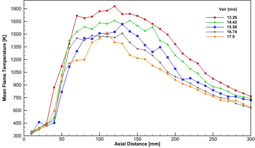
Adel Mohamed Hussien / Engineering Research Journal 171 (September 2021) M33- M50

 Inner flow
 jet
Outer flow
 shield

Figure (10) Shadowgraph images of IDFs with varying central air velocity at a constant
 ̅ = 0.026 m/s for major axis.
 fuel velocity,

 Vortical
 structure
 interaction

Figure (11) Shadowgraph images of IDFs with varying central air velocity at a constant
 ̅ = 0.026 m/s for minor axis.
 fuel velocity,
3.3.4 Axial and radial temperature measurement
In order to understand the thermal structure of the IDFs, temperature profiles including
the axial and radial temperature distributions and the temperature contour are introduced
in the next sub-sections.
3.3.4.1 Centerline Temperature Distribution (Axial Temperature)
The mean centerline temperatures of the LPG IDFs versus the axial distance y for
varying air velocities with a constant fuel velocity are shown in Figure (12). Generally,
the value of the peak means centerline temperature decreases with increasing the air
velocity. This is because the air velocity increasing causes cooling down the flame core
(central region) while the heat input remains constant, [32].
For all flames, the mean centerline temperature gradually increases in the vicinity of the
base flame up to the value of axial distance an almost (y=40mm) from the burner rim.
Then, the temperature increases by a very steep climb up to the blue zone (inner reaction
cone). The temperature has almost close values (the peak) due to the color of central
region evens out, [13]. The peak centerline temperature is reasonably coincident with
the blue zone, [2]. However, the temperature gradually decreases as the axial distance
ascends into the post combustion zone due to the heat release in the main flame is
transported by convection. This is due to the entrained cold ambient air dilutes and cools
down the combustion products.

 M44
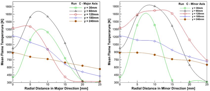
Adel Mohamed Hussien / Engineering Research Journal 171 (September 2021) M33- M50

The maximum temperature position within the blue zone (inner reaction cone) exhibits
position shifting while increasing the air velocity due to blue zone length variations, as
shown in Figure (12). With increasing the air velocity from 13.26 to 14.42 m/s, the peak
temperature position moves downstream the inner reaction zone. This is due to the inner
reaction zone is reconstructed and grows up during the conversion from the normal
diffusion flame to establish the IDF. While increasing the air velocity up to 17.9 m/s, the
peak temperature position gradually moved upstream the reaction zone. This is attributed
to the enhanced mixing between fuel and air, which leads to retract the inner reaction
zone. This is an indication to a shorter flame as discussed earlier. For the air velocity of
17.9 m/s, the peak value slightly increases due to the flame slender.

 Figure (12) Centerline temperature distribution with different air velocity at constant
 ̅ =0.026 m/s.
 fuel velocity of
3.3.4.2 Radial Temperature

Figure (13) shows radial profiles of temperature distribution for major and minor axes
at different axial distance (y=30, 60, 120, 180 and 240mm) at ̅ = 15.58m/s and
 ̅ =0.026m/s. The temperature profile at y=30 and 60mm, the temperature is low at the
flame centerline and increases sharply in the radial direction to the peak and then falls
rapidly. However, the temperature profile at y=120 mm poses the same trend but with
smoother variation. It is seen that the radial temperature profiles have peak values at the
radial positions from 5 to 10mm from the center-line. The rapid rise in the temperature
is attributed to the preheating of the air-fuel mixture form the reaction (combustion)
zone. After rising the mixture temperature to the reaction limit, the combustion occurs
forming the reaction zone with the highest temperature. Due to the high entrainment of
the ambient cold air, the temperature falls rapidly towards the outside of the flame in the
radial direction. The centerline temperature has the highest value in the radial profiles

 M45
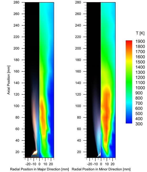
Adel Mohamed Hussien / Engineering Research Journal 171 (September 2021) M33- M50

for y=180 and 240mm. This is attributed to the cold ambient air entrained into the flame
that cools down the hot combustion products, [33].
Although the distributions of the radial temperature for the major and minor axes follow
the same trend as shown in Figure (13), there is a difference between them. For the entire
range of axial distance, the highest temperature on a minor axis is higher than that on
the major axis. This is attributed to non-homogenous fuel distribution through the
entraining air jet because the fuel is introduced through an elliptical tube around the
circular air jet. Also, at y=120mm, the temperature profile on minor axis is wider than
the profile on the major axis, that is because the flame in the minor plane (parallel to the
minor axis) is V-shape.

 (a) (b)
 Figure (13) Radial temperature distribution at different axial distance, y, for
 ̅ =15.58m/s and
 ̅ =0.026m/s; (a) Major direction (b) Minor direction.

The temperature contours for the major and minor axes under the same ̅ and ̅ , are
shown in Figure (14). The temperature distribution can be divided into four specific
regions, namely: the base flame zone, mixing zone, main reaction zone, and post-
combustion zone, [1],[33]. The base flame (entrainment zone) has relatively low
temperatures due to the low-temperature fresh reactants. The base flame comprises a
cool core which is located in the potential core region of the air jet. In the mixing zone,
the flame temperature steadily increases from the flame neck due to the chemical
reaction, while the temperature at the core of the flame is still cold due to the presence
of the air jet at the flame axis. The main reaction zone (inner reaction cone) is typically
associated with the maximum flame temperature. This is due to the completion of the
air/fuel mixing process and the release of more heat. The post-combustion zone is
associated with the decrease in the temperature due to the entrainment of ambient air
that cools down the hot combustion products, as well as the lower liberated heat. It can
be observed that the temperature contours are dense in the closeness of main reaction
zone.

 M46
Adel Mohamed Hussien / Engineering Research Journal 171 (September 2021) M33- M50

 ̅ = 15.58m/s and
Figure (14) Temperature contours of the IDF at ̅ =0.026m/s for both
 major and minor directions.

4 Conclusions
An experimental study is performed to investigate the stability limits and flame structure
of IDFs issuing from a concentric circular/elliptic burner. The stability limits of IDFs in
the present study is implemented by varying central air velocity at a constant fuel
velocity. The influences of varying central air velocity with constant fuel velocity on
flame appearance, shadowgraph imaging, flame length, and flame temperature
distribution were examined. The major conclusion of this study may be summarized as
follows:
 (1) The IDF structure comprise base and main flames. The base flame exhibits a pilot
 flame, which stabilizes the main flame. The base and main flames are separated
 by flame neck region with a soot ring around the flame neck. The appearance of
 IDFs characterizes dual structure (a bluish reaction zone confined in a diffusion
 combustion zone).

 (2) The flame stability comprises four stages, yellow flame, blue flame, local flame
 extinction and re-ignition, and main flame extinction zones. It was found that the
 blue flame zone lies above the yellow flame zone up to the air velocity value of
 22m/s. Also, the air velocity of 22m/s in conjunction with the fuel properties
 forms a strain rate limit for the stable blue flames.
 M47
Adel Mohamed Hussien / Engineering Research Journal 171 (September 2021) M33- M50

 (3) The main flame faces local extinction and re-ignition (flame tearing) at higher air
 velocity greater than 22m/s. The main flame extinction zone occurs for air
 velocity higher than 32m/s. furthermore, at a high air jet velocity, the main flame
 extinguishes from the flame neck resulting the base flame to remain attached to
 the burner rim preventing flame lift-off.

 (4) The visual analysis showed that with increasing the air velocity, the luminous
 zone, soot ring at the top of the base flame decreases and the flame becomes
 thinner. Also, the flame length decreases because of the improved fuel
 entrainment. Shadowgraph imaging of the flames show increased corrugation in
 the flames due to shorter flame with higher air velocity.

 (5) The peak mean centerline temperature decreases by up to 17.5% with increasing
 the air velocity. Moreover, the highest radial temperature on the minor axis is
 higher than that on the major axis due to the non-homogenous fuel distribution
 (elliptical fuel tube).

5 References
[1] V. Patel and R. Shah, 2019, “Effect of swirl and number of swirler vanes on
 combustion characteristics of methane inverse diffusion flame”, J. Mech. Sci.
 Technol., vol. 33, no. 4, pp. 1947–1958, doi: 10.1007/s12206-019-0345-7.
[2] V. Patel and R. Shah, 2018, “Experimental investigation on flame appearance and
 emission characteristics of LPG inverse diffusion flame with swirl”, Appl. Therm.
 Eng., vol. 137, pp.377–385,doi: 10.1016/j.applthermaleng.2018.03.105.
[3] V. Hariharan and D. P. Mishra, 2020, “Static flame stability of circumferentially
 arranged fuel port inverse jet non-premixed flame burner”, Combust. Sci.
 Technol., vol. 192, no. 8, pp. 1493–1519, , doi: 10.1080/00102202.2019.1611567.
[4] A. M. Elbaz and W. L. Roberts, 2016, “Experimental study of the inverse diffusion
 flame using high repetition rate OH/acetone PLIF and PIV”,Fuel, vol. 165, pp.
 447–461, doi: 10.1016/j.fuel.2015.10.096.
[5] L. K. Sze, C. S. Cheung, and C. W. Leung, 2006, “Appearance, temperature, and
 NOx emission of two inverse diffusion flames with different port design”,
 Combust. Flame, vol. 144, no. 1–2, pp. 237–248, doi: 10.1016/j.combustflame.
 2005.07.008.
[6] W. KT and E. RH, 1984, “Mapping and structure of inverse diffusion flames of
 methane”, in Proceeding of the proceedings of the 20th International symposium
 on combustion, the combustion institute, pp. 1925–32.
[7] S. Mahesh and D. P. Mishra, 2008, “Flame stability and emission characteristics
 of turbulent LPG IDF in a backstep burner”, Fuel, vol. 87, no. 12, pp. 2614–2619,
 doi: 10.1016/j.fuel.2008.02.001.
[8] S. Mahesh and D. P. Mishra, 2011, “Study of the turbulent inverse diffusion flame
 in recessed backstep and coaxial burners”, Combust. Explos. Shock Waves, vol.
 47, no. 3, pp. 274–279, doi: 10.1134/S0010508211030038.

 M48
Adel Mohamed Hussien / Engineering Research Journal 171 (September 2021) M33- M50

[9] A. M. Elbaz and W. L. Roberts, 2014, “Flame structure of methane inverse
 diffusion flame”, Exp. Therm. Fluid Sci., vol. 56, pp. 23–32, doi:
 10.1016/j.expthermflusci.2013.11.011.
[10] S. Mahesh and D. P. Mishra, 2015, “Flame stability limits and near blowout
 characteristics of CNG inverse jet flame”, Fuel, vol. 153, no. February, pp. 267–
 275, doi: 10.1016/j.fuel.2015.02.074.
[11] M. A. Mikofski, T. C. Williams, C. R. Shaddix, and L. G. Blevins, 2004 “Effect
 of varied air flow on flame structure of laminar inverse diffusion flame”,Combust.
 Inst., pp. 04S – 7.
[12] M. A. Mikofski, T. C. Williams, C. R. Shaddix, and L. G. Blevins, 2006, “Flame
 height measurement of laminar inverse diffusion flames”, Combust. Flame, vol.
 146, no. 1–2, pp. 63–72, doi: 10.1016/j.combustflame.2006.04.006.
[13] A. Sobiesiak and J. C. Wenzell, 2005, “Characteristics and structure of inverse
 flames of natural gas” ,Proc. Combust. Inst., vol. 30, no. 1, pp. 743–749, doi:
 10.1016/j.proci.2004.08.173.
[14] S. Mahesh and D. P. Mishra, 2010, “Flame structure of LPG-air Inverse Diffusion
 Flame in a backstep burner”, Fuel, vol. 89, no. 8, pp. 2145–2148, doi:
 10.1016/j.fuel.2010.01.030.
[15] A. M. Elbaz and W. L. Roberts, 2014, “Experimental characterization of methane
 inverse diffusion flame”, Combust. Sci. Technol., vol. 186, no. 9, pp. 1249–1272,
 doi: 10.1080/00102202.2014.920835.
[16] L. L. Dong, C. S. Cheung, and C. W. Leung, 2007, “Heat transfer characteristics
 of an impinging inverse diffusion flame jet – Part I: Free flame structure”, Int. J.
 HeatMassTransf.,vol.50,no.25–26,pp.5108–5123,Dec,doi:
 10.1016/j.ijheatmasstransfer.2007.07.018.
[17] h. S. Zhen, c. W. Leung, and c. S. Cheung, 2010, “thermal and emission
 characteristics of a turbulent swirling inverse diffusion flame”, int. J. Heat mass
 transf.,vol.53,no.5–6,pp.902–909, doi: 10.1016/j.ijheatmasstransfer.2009.11.034.
[18] H. S. Zhen, C. W. Leung, and C. S. Cheung, 2011, “A comparison of the thermal,
 emission and heat transfer characteristics of swirl-stabilized premixed and
 inverse diffusion flames”, Energy Convers. Manag., vol. 52, no. 2, pp. 1263–1271,
 doi: 10.1016/j.enconman.2010.09.023.
[19] B. Stelzner, F. Hunger, S. Voss, J. Keller, C. Hasse, and D. Trimis, 2013,
 “Experimental and numerical study of rich inverse diffusion flame structure”
 ,Proc.Combust.Inst.,vol.34,no.1,pp.1045–1055,doi: 10.1016/j.proci.2012.06.153.
[20] V. Patel and R. Shah,2017, “Experimental and Numerical Investigation of LPG
 Fuelled Inverse Diffusion Flame in a Coaxial Burner”, Adv. Thermofluid Res.,
 vol. 3, no. 1, pp. 16–29.
[21] B. D. Baird and S. R. Gollahalli, 2003,“ Effect of aspect ratio on stability and
 global emission characteristics of pre-mixed elliptical burner flames”, 1st Int.
 Energy Convers. Eng. Conf. IECEC, pp. 1–6,doi: 10.2514/6.2003-5948.

 M49
Adel Mohamed Hussien / Engineering Research Journal 171 (September 2021) M33- M50

[22] B. D. Baird and S. R. Gollahalli, 2006, “Effects of temperature and hydroxyl
 radical concentration distributions on emissions of partially premixed flames
 from elliptical burners”, Proc. ASME Turbo Expo, vol. 1, pp. 51–56, doi:
 10.1115/GT2006-90065.
[23] P. Hariharan, C. Periasamy, and S. R. Gollahalli, 2007, “Effect of elliptic burner
 geometry and air equivalence ratio on the nitric oxide emissions from turbulent
 hydrogen flames”, Int. J. Hydrogen Energy, vol. 32, no. 8, pp. 1095–1102, doi:
 10.1016/j.ijhydene.2006.07.009.
[24] S. K. S. Chinthamony, C. Periasamy, and S. R. Gollahalli, 2007, “Stability and
 global emission characteristics of elliptic burner diffusion flames in an elliptic
 co-flow”, Collect. Tech. Pap. - 45th AIAA Aerosp. Sci. Meet., vol. 11, no.
 January, pp. 7200–7209, doi: 10.2514/6.2007-599.
[25] O. A. Kashkousha, M. M. Kamal, A. M. Abdulaziz, and M. A. Nosier, 2012,
 “Concentric elliptical jet diffusion flames with co- and cross-flows”, Exp. Therm.
 Fluid Sci., vol. 41, pp. 177–187, doi: 10.1016/j.expthermflusci.2012.03.033.
[26] A. M. R. Attia, H. S. Ayoub, and B. Ghazolin, 2018, “In-Situ Soot visualization
 using Low power 405nm laser shadowgraphy for premixed and non-premixed
 flames”, Phys. AUC, vol. 28, pp. 12–16.
[27] H. E. Saleh, 2008, “Effect of variation in LPG composition on emissions and
 performance in a dual fuel diesel engine”, Fuel, vol. 87, no. 13–14, pp. 3031–
 3039, doi: 10.1016/j.fuel.2008.04.007.
[28] A. M. Elbaz, H. A. Moneib, K. M. Shebil, and W. L. Roberts, 2019, “Low NOX -
 LPG staged combustion double swirl flames”, Renew. Energy, vol. 138, no. X,
 pp. 303–315, doi: 10.1016/j.renene.2019.01.070.
[29] Y. A. Cengel, “Heat Transference a Practical Approach,” MacGraw-Hill, vol. 4,
 no. 9, p. 874, 2004.
[30] F. C. Lockwood and H. A. Moneib, 1982,“Fluctuating temperature measurements
 in turbulent jet diffusion flame”, Combust. Flame, vol. 47, no. C, pp. 291–314,
 doi: 10.1016/0010-2180(82)90108-0.
[31] L. L. Dong, C. S. Cheung, and C. W. Leung, 2011, “Combustion optimization of
 a port-array inverse diffusion flame jet”, Energy, vol. 36, no. 5, pp. 2834–2846,
 doi: 10.1016/j.energy.2011.02.025.
[32] V. Hariharan and D. P. Mishra, 2020,“Experimental Characterization of
 Circumferentially Arranged Fuel Port Inverse Jet Diffusion Flame
 Burner”,Combust.Sci.Technol.,vol.192,no.12,pp.2306–2325,doi:
 10.1080/00102202.2019.1643847.
[33] H. S. Zhen, C. S. Cheung, C. W. Leung, and H. B. Li, 2013, “Thermal and heat
 transfer behaviors of an inverse diffusion flame with induced swirl”, Fuel, vol.
 103, pp. 212–219, doi: 10.1016/j.fuel.2012.05.026.

 M50
You can also read