DuraCode Series OPERATION MANUAL - DURACODE 200 SERIES TOUCHSCREEN Continuous Inkjet Printer - Inkjet, Inc.
←
→
Page content transcription
If your browser does not render page correctly, please read the page content below
DuraCode Series
DURACODE 200 SERIES TOUCHSCREEN
      Continuous Inkjet Printer

  OPERATION MANUAL

      www.inkjetinc.com | 1-800-280-3245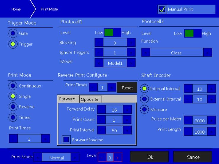
Compliance Information
This equipment has been tested and found to comply with the limits for a Class A digital device,
pursuant to part 15 of the FCC Rules. These limits are designed to provide reasonable protection
against harmful interference when the equipment is operated in a commercial environment. This
equipment generates, uses, and can radiate radio frequency energy and, if not installed and used
in accordance with the instruction manual. Operation of this equipment in a residential area is
likely to cause harmful interference, in which case the user will be required to correct the
interference at his own expense.

2006/42/EC                                   Machinery Directive
2014/35/EU                                   Low Voltage Directive
2014/30/EU                                   Electromagnetic Compatibility Directive
EN ISO 12100:2010                            Safety of machinery – General principles for
                                             Design – Risk assessment and risk reduction
EN 60204-1:2006+A1:2009+AC:2010              Safety of machinery – Electrical equipment of
                                             machines – General requirements
EN 55032:2015                                Electromagnetic compatibility of multimedia
                                             Equipment – Emissions requirements
EN 55024:2010+A1:2015                        Information technology equipment –
                                             Immunity characteristics – Limits and methods
                                             of measurement
EN 61000-3-2: 2014                           Electromagnetic compatibility – Part 3-2 Limits
                                             for harmonic current emissions
EN 61000-3-3:2013                            Electromagnetic compatibility – Part 3-3 Limits
                                             of voltage changes, voltage fluctuations and
                                             flicker in low-voltage supply systems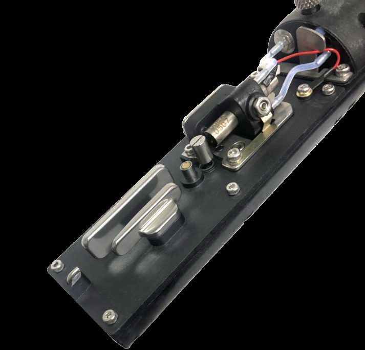
Table of Contents
1. Safety ------------------------------------------------------ 1
   1.1 Safety Outline                                                                 1
   1.2 Safety Measures                                                                1
   1.3 Safety Considerations                                                          1
   1.4 Handling                                                                       2
   1.5 Responsibilities                                                               2
2. Main Parts ------------------------------------------------ 3
   2.1 IJI DURACODE 200 SERIES TOUCHSCREEN Printer                                    3
   2.2 Printhead                                                                      4
   2.3 Ink Module                                                                     4
   2.4 Electrical System                                                              5
3. Operating Software------------------------------------ 6
   3.1 Home Page                                                                      6
   3.2 Run Info                                                                       7
   3.3 Print Mode                                                                     8
   3.4 Print Management                                                             10
      3.4.1 Select Printing Information --------------------------------------------- 10
      3 4.2 Print Editing                                                           11
      3 4.3 Print Parameters                                                        12
      3 4.4 Text                                                                    13
      3 4.5 Multi Text                                                              14
      3 4.6 Timer                                                                   15
      3 4.7 Shift                                                                   16
      3 4.8 Counter                                                                 16
      3 4.9 Picture                                                                 17
      3.4.10 Barcode                                                                18
      3 4.11 Ext Data                                                               19
      3.4.12 Print file import and export-------------------------------------------- 20
      3.4.13Photo management                                                        20

 4. System settings ------------------------------------ 21
     4.1 Authorization                                                              21
     4.2 Printer Config                                                             22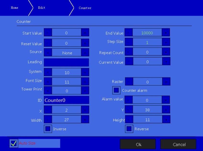
4.3 Debug                                                                   23
     4.4 Cleaning                                                                23
     4.5 Ink System                                                              24
     4.6 Network Setting                                                         24
     4.7 Serial Port                                                             28
     4.8 Date/Time Code                                                          30
     4.9 About                                                                   31
5. Printer operation ------------------------------------- 32
   5.1 First use of the Printer                                                  32
   5.2 How to start printing                                                     30
                                                          5.2.1 Start ink-jet     33
      5 2.2 Correct jet alignment                                                34
      5 2.3 Correct inkjet breakpoint                                            35
   5.3 Stop and clean the ink jet printer ------------------------------- 36
      5 3.1 Stop and clean                                                       36
      5.3.2 Shutdown and cleaning (power off during use) ------------------- 36
      5.3.3 Shutdown and cleaning (long-term stop) --------------------------- 36
   5.4 Failure and warning icons ---------------------------------------- 37
      5.4.1 Failure icons and meanings-------------------------------------------- 37
      5.4.2 Warning icons and meanings ------------------------------------------ 38
   5.5 Troubleshooting without icon prompt -------------------------- 39
   5.6 Nozzle cleaning                                                           41
   5.7 Ink jet adjustment                                                        42
   5.8 System cleaning                                                           43
   5.9 Sensor and Encoder wiring diagram --------------------------- 43
        5 9.1 Sensor diagram                                                     43
        5 9.2 Encoder wiring diagram                                             43
   5.10 Specifications                                                           44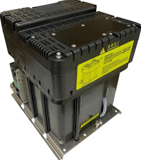
1. Safety
  1.1 Safety Outline
      • Only trained individuals should attempt maintenance of this equipment. Failure to do
          so could result in damage or personal injury.

      • Lethal voltages are present within this equipment when it is connected to the
          mains electrical supply. Only trained and authorized personnel must carry out
          the maintenance work. Observe all statutory electrical safety codes and
          practices. Unless it is necessary to run the printer, disconnect the printer from
          the mains electrical supply before removing the covers or attempting any
          service or repair activity. Non-adherence to this warning can result in death or
          personal injury.
      •   The consumables used for the ink jet printer are combustible liquid. The consumables
          used must comply with the instructions in the Material Safety Data Sheet (MSDS).
          Meanwhile, the ink jet printer must also be subject to regular inspection and
          maintenance to eliminate potential safety hazards.

  1.2 Safety Measures
      • The ink jet printer must be installed in a safe, firm and stable way with good
          grounding.

      • The ink jet printer must be installed at a ventilated place, and far from the heat
          source, fire source and static electricity. Smoking near the ink jet printer is prohibited.

      • The covers of the containers for the printing ink, solvent and cleaning agent used for
          the ink jet printer must be tightly closed, and they shall be stored in a ventilated
          environment far from the ink jet printer.

      • The ink jet printer shall be maintained clean, because the consumable used may be
          the combustible liquid. The printing ink may also be subject to combustion after being
          dried.

      • A carbon dioxide dry powder fire extinguisher shall be arranged near the ink jet
          printer.

  1.3 Safety Considerations
      • The ink jet printer is non-contact ink-jet equipment, and is not applicable for all
          occasions (such as the explosive environment). The user must comply with the safety
          criterion and provide an appropriate working environment during use. Otherwise, the
          consequences caused shall be assumed by the user.

      • The consumables of the original factory or permitted by the original factory (including
          the printing ink, solvent, cleaning agent, maintenance products and so on) must be
          used. The Material Safety Data Sheet (MSDS) must be ahered to and carefully read
          and observed. Otherwise, the consequences caused shall be assumed by the user.

      • Those who may touch the consumables during operation shall wear the ink-resistant
          gloves and protective glasses.

                                           1
1.4 Handling
    • The machine with printing ink or solvent in it must be handled in a vertical way. If the
      ink jet printer cannot be always maintained at the vertical state, the printing ink and
      solvent shall be completely discharged before handling.

1.5 Responsibilities
    • During use and maintenance of the equipment, the company shall not be responsible
      for any consequence caused by any behavior against the safety instructions, safety
      requirements and basic safety operation criterion.

                                      2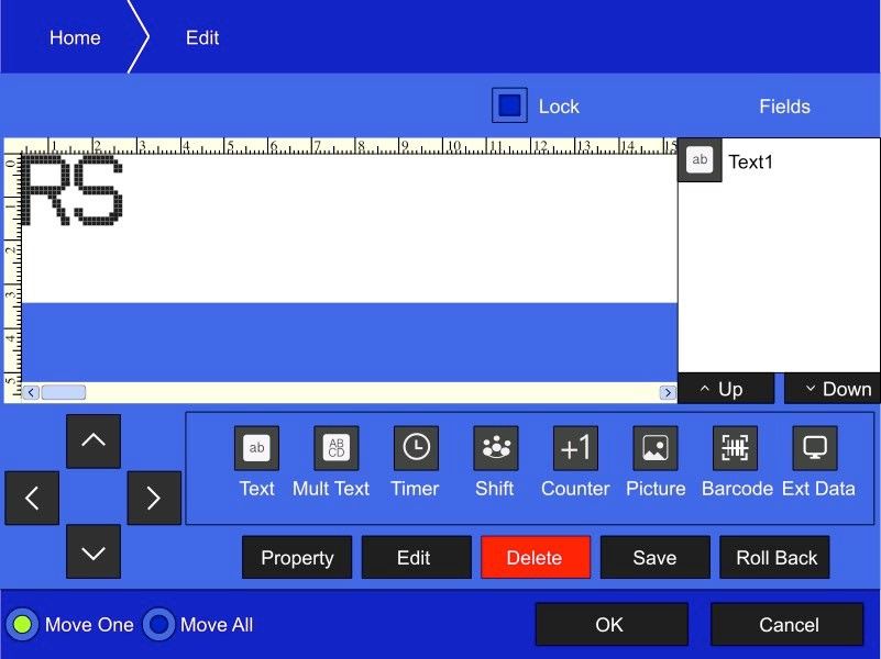
2. Main Parts
  2.1 Overview

        Right View                   Front View                 Left View

       Instructions for direction:

       1. Main power switch

       2. Upper overview: Electronics Compartment and Control Panel

       3. Lower overview: Ink compartment

       4. Connector Panel

       5. Umbilical

                                     Page 3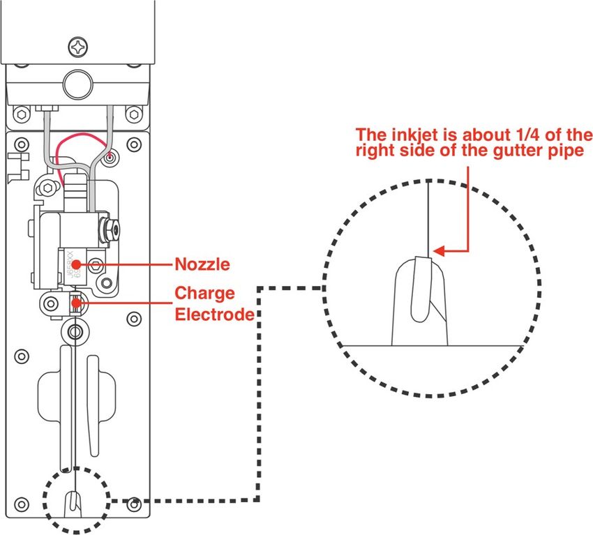
2.2 Printhead

                   Last Chance Filter                       Printhead Screw

                                                             Crystal Screw

                                                             GND for Nozzle

                    Charge Electrode
                                                              Phase Detector

            Nagetive Deflection Plate                         Positive Deflection Plate

                                                              Gutter Sensing Tube

    2.3 Ink Module

Condenser                                   * Exhaust Air Switch
Cover
                                                    Manifold

                                                Socket V6                                      Filter

                                                                                          Addition Pump
                                           Drain Pipe
                                                                                            Flushing
                                                 Gear Pump
                                                                                            Pump
 * Exhaust Vent Plug

                   Ink Core (Front View)                          Ink Core (Back View)

                                                Page 4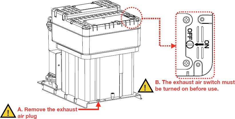
2.4 Electrical System

                                                          5

                 1                                        4

                 2                                        3

     Instructions for direction:

     1. Extra High Tension (EHT/HV)

     2. Positive Air Pump (Some models do not include )

     3. Mainboard (Not visible from this view)

     4. Power Supply Unit

     5. Display driver board

                                     Page 5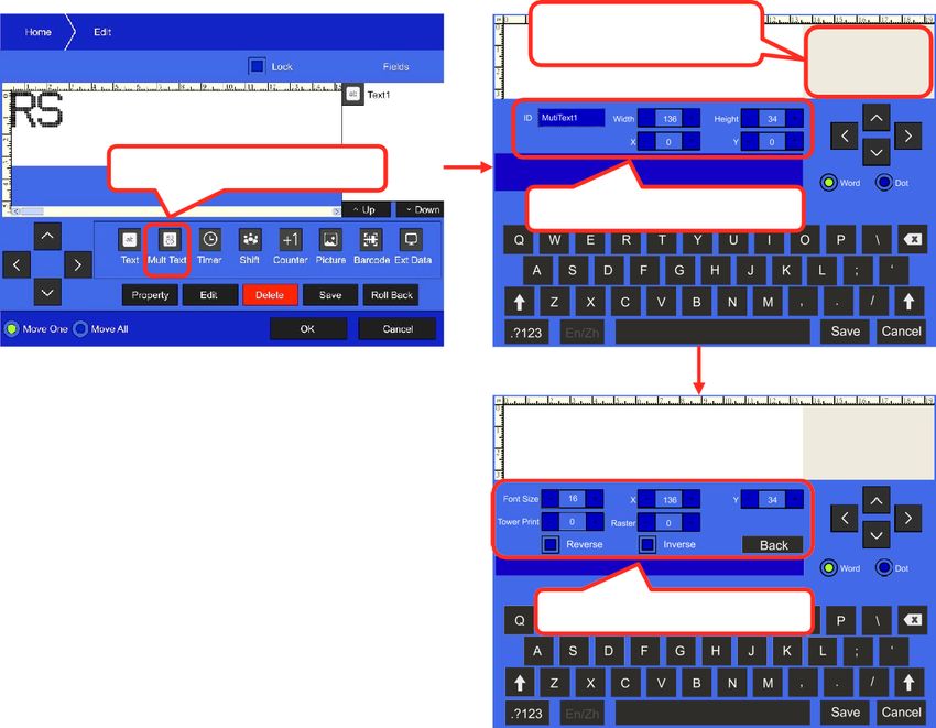
3. Operating Software
  3.1 Home Page
         The main screen is the default screen

          after the ink jet printer is powered on, and the main window is shown in the following
         figure:

     1

     2

     3

                                                                                        4

     5
                                                                                        6

     7

         Instructions for direction:
         1. Device Status Bar

         2. Error and Warning Information Bar

         3. Current Message Details Bar

         4. Back, Zoom out and Zoom in the current job

         5. Name of the current job,Total Prints Counter

         6. Consumable Levels Information

         7. Control Buttons

                                         Page 6
3.2 Run Info
The information Interface contains critical real time running status such as ink pressure, ink
temperature and Print stability checks etc.
Click the Run Info button on the main screen:
Instructions::
1. Pump Ink Pressure: Printer currently detected pressure value
2. Ink Temp: Real-time temperature measurement in ℃ of the ink in the ink module.
3. Cabinet Temp: Real- time measurement of internal cabinet temperature
4. Head Temp: The current detected printhead temperature;
5. Phase Angle / Phase Profile: Real-time status of phase angle and the number of phase.
6. Measuring Cup: The level of fluid in the measuring tank. High indicates filled, Low
indicates empty.
7. Chamber: Liquid level state of the viscosity detection chamber – High to show filled and
Low to show empty.
8. VMS: Indicates time to empty of the VMS chamber. The Set value is the optimum point
according to the ink type. Now is the measured actual value .
9. Mixer: This is the ink level state in the mixer chamber. Normal is Low ON, OK ON. This
indicates correct level. Low indicates not enough ink to circulate and High indicates overfill
condition.
10. Modulation: The current modulation value.
11. EHT value: Reference value for EHT calibration, value1 is the low value and value2 is
the high Value.
12. Timer: Displays the current time.
Page 73.3 Print Mode
1. Follow the steps as follow:
a.Touch This Area
b. Click Print Mode
2. Enter "Print Mode" interface.
8
2
1 3
4 6
5
7
Instructions:
1. Trigger Mode:
o The way of the external photocell triggers printing, Gate or Trigger optional .
2. Photocell 1:
o Level: Printing is triggered when the photocell 1 obtains the high or low level
signal. Set according to sensor used;
o Blocking time: This is a time in milli seconds to inhibit the trigger of the sensor
following a print and is used to prevent unwanted additional print triggers
o Ignore Triggers: Sets the number of print triggers to ignore following a print
o Model: Select the external sensor signal processing mode;
Page 83. Photocell 2:
o Level: The corresponding function selected is triggered when the photocell 2
obtains the high / low level signal;
o Function: Disable, Reset counter, Traversing print control , Reset traversing
print , Opposite print and Reset detection & counting are optional.
4. Print Mode:
o Continuous : Enable continuous print mode
o Single : Enable single print mode
o Reverse : Enable traverse print mode
o Times : Enable repeat print mode
• Print times: Only active if the Times mode is selected and prints a set
number of times for a single print trigger
5. Reverse Print Configure:
o Print Times: Sets number of prints for each sensor trigger
o Forward:
• Forward delay: Sets the delay in milli seconds of the first print in the forward
traverse
• Print Count: Use to set forward print times
• Print Interval: Set the interval between each forward printings.
• Print Inverse: Enables on reverse / inverse print on alternate prints on forwards
traverse
o Opposite:
• Opposite delay: Sets the delay on first print of the return traverse
• Print Count: Use to set opposite print times
• Print Interval: Set the interval between each opposite printings.
• Opposite Inverse: Enables on reverse / inverse print on alternate prints on
return traverse.
6. Shaft Encoder:
o Internal interval: Set when no encoder fitted. Sets width of print in time
o External interval: Set when external encoder fitted
o Measure: Selected when meter marking
o Pulses per meter: Calibrates the encoder in use to meter mark. The number of
pulses per meter is set in the pulses per meter box. For example, if the
circumference of the encoder wheel is 250mm and the pulses per revolution of the
endcoder is 2000 then number of pulses per meter is (1000÷250) x 2000 = 8000
pulses per meter.
o Print length: This is the number of pulses to trigger a printing in continuous mode
7. Print Mode:
o Mode Selection: Normal, High Quality, High Speed.
o Level: Range 0 to 15(For High Quality Only)
8. Manual Print:
o Manual Print : Enable the “Manual Print” button on the main screen.
Page 93.4 Message Management
3.4.1 Select Printing Message
1. Follow the steps as follow:
a.Touch This Area
b. Click Manage Job
2. Enter "Manage Job" interface.
3. Select from here
4. Then Click To Print
3. Select the job from the list then click “To Print” button.
Page 103.4.2 Edit Printing Message
1. Follow the steps as follow:
a.Touch This Area
2. Click Edit botton
2. Enter "Edit" interface.
1 3
4
2
5
Instructions:
1. The message contents display in this area.
2. Use to move the contents’ position .
3. All the contents will list here
4. All kinds of contents here can be added from here.
5. Use to adjust parameters, modify content ,delete content, save content and roll back.
Page 113.4.3 Modify Message Parameters
1. Follow the steps as follow:
a.Touch This Area
2. Click Property botton
3. You can enter the parameters attributes directy from this interface. As shown below:
1
2
3
4
Instructions for direction:
1. Dots: Range 5-34, Select the number of the dots subject to required print height
in dots. The larger the value is, the slower the printing speed will be.
Delay: Range 3-10000, Sets the printing delay time. This sets the time from the
print trigger to the start of printing position.
2. Width: This setting adjusts the width of print. The smaller the value is, the
narrower the printing character will. Value is 1 is maximum print speed for a
given font
Height: Range 1-10, Adjusts the height of the print.
3. Gap: Range 0-8, Adjusts the gap between printed characters in rasters. The
larger the value is, the larger the character spacing is.
Raster: Range 0-7, Adjusts the bold times of message.
4. Inverse, Reverse: Orientates the print read direction
Page 123.4.4 Text
1. At the Editing interface( refer to 3.4.2 Edit Printing Message) , tap the Text icon
a.Tap ‘Text’ icon
Instructions for direction:
1. Text: Message contents can be filled in or modified here;
2. Font Size: 5*5、6*5、7*4、7*5、9*6、9*6B、11*8、11*8B、16*11、24*17、
32*22 dot-matrix fonts can be selected;
Raster: Bold the text, 0-7 bold times can be selected;
3. Tower print: 0 and 90 can be selected, the single-line text can be printed in the
tower shaped font if it set to 90.
4. ID: Field name of the single-line text for fast selection
5. X, Y: Position of the text string in the edit field. When the position of the single-line
text is 0, 0, the single-line text is aligned with the upper left corner of the edit field
6. Width, height: Sets the width and height of the text
7. Inverse, Reverse: Sets the orientation of the text
8. Auto Size: The width and height values will be automatically set after selected.
Page 133.4.5 Multi Text
1. At the Editing interface(refer to 3.4.2 Edit Printing Message), tap the Mult Text icon
Touch here to switch
to font parameter
a.Tap ‘Mult Text’ icon
b. Mult Text parameters
c. Fonts’ parameters
Mult Text parameters:
• ID: Field name of the Mult-Text for fast selection;
• Width,Height: Size of the layout. Width maximum 4000 dots
• X,Y: Position of the Mult-Text in the message;
Fonts’ parameters:
• Fonts: 5, 6*5, 7*4, 7, 9, 11, 16, 24, 32 dot-matrix fonts can be selected;
• X,Y: Position of the text in the edit field;
• Tower Print: The Mult-text can be printed in the tower shaped font;
• Inverse, Reverse: Sets the orientation of the text print
Page 143.4.6 Timer
At the Editing interface, drag and drop the Timer icon to the message layout to add
the dynamic clock. The setting interface is as follows:
a.Tap ‘Timer’ icon
Instructions for direction:
1. Format: Choose the format for timer in dropdown list
2. Confirm Unit, Value: Day, Month, Year
3. Font Size: 5, 6*5, 7*4, 7, 9, 11, 16, 24, 32 dot-matrix fonts can be selected;
Deviation: Days in advance to print
4. Tower print: On selection, the single-line text can be printed in the tower-shaped
font
Raster: Bowdlerization of the single-line text, 0-9 bold times can be selected;
5. ID: Name of the Timer
6. X, Y: Position of the single-line text in the print
7. Width, height: Width and height of the print
8. Inverse, Reverse: Orientation of the print
9. Auto Size: The width and height values will be automatically set after ticking.
Page 153.4.7 Shift
At the Print editing interface, click the "Shift" button to add the shift information. The
setting interface is as follows:
a.Tap ‘Shift’ icon
3.4.8 Counter
At the Print editing interface, click the "counter" button to add the counter
information. The setting interface is as follows:
Content
agreement
Jet printing
format
Instructions for direction
1. Start value, End Value: Starting value and end value of the counter. The
maximum value which can be input by the user is 1,999,999,999.
2. Reset Value: Reset value of the counter.
Step Size: Step Size of the counter.
3. Source: When the counter data source is selected, and the data source counter
reaches the maximum value, the secondary time counter changes a step value.
Page 16Repeat Count : 1 at default, printing times of each current value. For example, if
set as 2, each counter value will be printed for 2 times.
Page 174. Leading Char: When "0" is filled in, the ink jet printer guarantees that the counter
lengths printed are consistent. For example, if the counter defined by the user is 9
digits, but the actual counting value is only 6 digits, 3 zero will be added in front of the
6-digit counting value.
Current Value: Current Value of the counter.
5. System:Base format of the counter
Jet printing format:
Refer to section 3.4.4 .
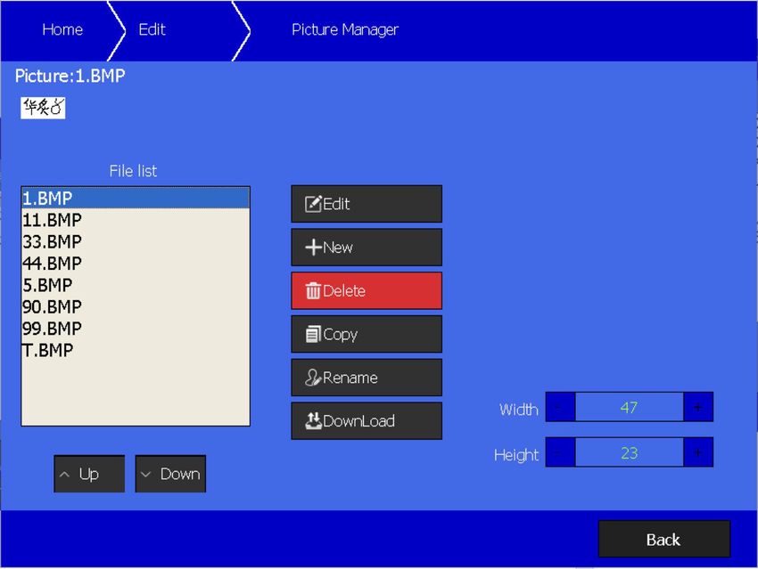
3.4.9 Picture
At the print editing interface, click the "Picture" button to add picture. The setting
interface is as follows:
The photo editing interface is shown in the following figure:
Remark:The printer only accepts monochrome *.BMP files and *.PIC files,
the maximum size must be in range 250*34 dots
Page 183.4.10 Barcode
At the information editing interface, click the "Barcode" button to add the
corresponding code. The interface is as follows:
9 1
2
3
4
5
6
10 7
8
Instructions for direction:
1. ID: Name of barcode;
2. Text: Fixed barcode contents;
3. Barcode Type: EAN8, EAN13, code39, code128, QR Code, Data_Matrix;
4. Font Size: If Barcode Type is one of EAN8, EAN13, code39, code128, it can be
selected:
5. Raster: Bolding of 1D Barcode, 0-9 bolding times can be selected;
6. X, Y: Coordinates of the position of Barcode;
7. Width,Height: Size of barcode, 1D Barcode is automatically generated;
8. Reverse and Inverted: Orientates the print
9. Barcode real-time preview area;
10. Add data item to the barcode, and add single-line text, clock, shift, counter and
external data. Once the data item is added, the contents filled in the Text of Item 2
will be invalid;
11. When the type is selected, the number of characters is limited by the size of the
QR code:
Code size 33*33 29*29 25*25 21*21
Maximum number of characters 114 77 47 25
Page 193.4.11 Ext Data
At the print editing interface, click the “Ext Data" button to add Ext Data. The
interface is as follows:
1
2
Instructions for direction:
1. Code: The identification code of external data communication is corresponding to
the "user area" in the calculation software;
Length: Data bit transmitted from the computer to the ink jet printer;
2. Refer to section 3.4.4.
Page 203.4.12 Print file import and export
Touch the message area at the homepage, select “Manage Job", and click
"download" button. The interface is as follows:
Select the corresponding information, click the corresponding transmission icon to
transmit print layout between the system and USB disk. The file will also include the
print parameters;
3.4.13 Photo management
Touch the message area at the homepage, Select “Edit" , click "Picture" button, and
click "download" button to transmit Pictures between the system and USB disk.
Accept monochrome BMP file only, size limit 34x255
The interface is as follows:
Page 214. System settings
Click "Settings" icon at the homepage to enter the system setting main interface, as
shown in the following figure:
4.1 Authorization
At the "Settings" interface, click the "Authorization setting" icon. The interface can
be set with passwords of two levels and the corresponding authority. The interface is
as follows:
224.2 Printer Config
At the " Settings " interface, click "Settings" icon
1 4
2
3 5
Instructions for direction:
1. Printer
• Ink Type: Sets the type of the ink used.
• Running pressure: Sets the system running pressure.
• VMS Check: When turned on, viscosity is automatically set, and manual
setting is invalid. Normal ON
• EHT Trip Level: Sets the high-voltage leakage alarm value.
• Auto Modulation:Adjust the modulation automatically but takes effect
during startup only.
• Heater Temp: Sets the printhead heating temperature.
• VMS Calibration: when VMS automatic detection is turned off, the ink
viscosity can be set automatically.
• Gutter Mode: Sets the recovery mode of ink through the gutter.
• Modulation Set : Sets the nozzle modulation value.
2. Speed Ratio: This setting affects ratio of a. Width, b. Delay c. Internal interval d.
External interval. Increase from default 1 will factor increase the set widths and
delays in parameter and print mode screens. Used to increase range of each
setting (Width, Delay, Intervals). Global setting so all are affected by a ratio
change.
3. Charge / Gutter shutdown control: When boxes are unchecked this prevents
automatic shutdown in event of charge or gutter fault. Default checked.
4. Phase charging setting:
• Phase Offset: Sets the phase compensation value
• Phase Charge: Sets the phase charging value
• Charge: Sets the ink dot charging value
5. Atmospheric pump: Activates positive air pressure to the print head;
234.3 Debug
Click "Debug" icon in "Settings" to singly control the pump, valve or fan, as shown in
the figure:
4.4 Cleaning
Click the icon of "Cleaning" in the "Settings" to enter the Cleaning interface, as shown
in the figure:
Cleaning
Instructions for function option:
1. Wash Nozzle: Nozzle used for automatic washing of blockage;
2. Nozzle Flush: After selection, open the printhead cover, and manually clean the
nozzle with correct cleaning agent;
244.5 Ink System
Click the icon of "Ink System" in the "Settings" to enter the ink system interface, as
shown in the figure:
Instructions for function option:
1. Umbilical Purge: Used to clean the printhead supply pipes during commissioning
by the trained engineers only;
2. Quick Start Jet: Used to rapidly turn on the ink jet printer, no pipeline automatic
cleaning;
3. Quick Stop Jet: Used to rapidly stop ink-jet, no pipeline automatic cleaning;
4. Pressure Zero Offset: Used to calibrate the standard reference pressure;
5. Clean Ink System: Used for cleaning of the whole ink system;
6. Exhaust Air From Ink System: Used to empty air in the ink way, for example, use
during the first use;
7. Fill Mixer: Used to Fill the mixer when printer is first use and mixer empty.
8. Drain: Used to emptying the ink in the ink module, finish the drain operation
according to the system prompt.
9. System Clean: used to clean the ink system,finish the cleaning operation
according to the system prompt.
4.6 EHT Calibration
Before executing this procedure, make sure that the machine ink system is
not started and that the printhead cover is installed on the printhead
correctly.When the program is completed, a prompt screen will pop up.
254.7 EHT Setting
Used to assign EHT values to different print height. The values have been set
before the machine leaving the factory, and usually there is no need to set it
again during use.
264.8 Network Setting
Click the icon of " Network " in the " Settings " to enter the net setting interface, as
shown in the figure:
Instructions for function option:
1. IP Addr: Used to set the IP address
2. Subnet Mask: Used to set the Subnet Mask
3. Default Gateway: Used to set the Default Gateway
4. DNS: Used to set the DNS
5. Local Port: Used to set Local Port
6. Server Port: Used to set the Server Port
7. Server IP: Used to set the Server IP
7. Connect Type: Used to choose connect type, UDP and TCP/IP.
274.9 Character Format
Different styles of characters "0", "1" and "5" can be selected here,the printer
needs to be reboot when the styles changed.
284.10 Serial Port
Click the icon of " Serial Port " in the " Settings " to enter the serial port setting
interface, as shown in the figure:
Instructions for function option:
Serial Setting:
1. Baud rate: Used to change the baud rate.
2. Tranc Model: Used to choose the transfer mode, Printed / Tranc end.
3. External data Printing:
Non repeating printing: Printer only print the latest data once.
Print the latest data: Printer will print repeat the last data.
Data Source:
4. 232 Date: External data transfer from serial port
5. Lan Data: External data transfer from Ethernet interface
6. USB Scanner: External data transfer from barcode scanner
294.11 Language
Used to select the display language of the system
4.12 Screen Calibration
This can be used for calibration when the touch screen key position is
inaccurate, Press the cross icon in turn to complete the calibration
4.13 System Time/Date
Used to calibrate system time of the printer
4.14 Service Time
Used for reset maintenance time after system maintenance
304.15 Date/Time Code
Click the icon of " Date/Time Code " in the " Settings " to enter the date and time
code setting interface, as shown in the figure:
Instructions:
These settings are used to define the printed date information including
year,month,day,hour and minute.
For example: With reference to above picture, to modify what is printed for the current
year, modify the code of 17 to a required code, for example AB. The printing result will
be 20AB if the system clock includes year in the print message.
4.16 Counter alarm
Parameters used to set the counting alarm function
314.17 About
Click the icon of " About " in the " Settings " to enter the interface, as shown in the
figure:
Instructions:
1. Software version: it can be update by USB.
325. Printer operation
5.1 First use of the Printer
Printer needs to be filled with ink and exhaust air before use.
1. Open the lower cabin door and install the correct ink and makeup to the correct position
according to the label .
2. Pull out the ink system, remove the exhaust air plug at the bottom (Refer to step A.)*, and use a
screwdriver to open the top exhaust air switch (Refer to step B.)* as shown in figure:
3. Push the ink system into the cabin and close the lower cabin door .
4. Connect the printer to an appropriate power source and power on the printer.
5. Enter the SETINGS-INK SYSTEM menu, perform Fill Mixer program wait for about 30 minutes
until the screen shows “Fill Mixer Tank Finish”.
6. Enter the SETIINGS - INK SYSTEM menu and perform Exhaust Air program to complete ink
way priming. Screen prompt will advise when complete. NOTE: Ink will come from the gutter,
place a catcher under the printhead.
7. Clean the printhead.
• During normal use of the printer, the exhaust vent plug A needs to be removed, and the exhaust air
switch B needs to be opened , otherwise it will cause printer failure.
• Executing a Fill Mixer may result in an ink remaining percentage deviation.
335.2 How to start printing
5.2.1 Start ink-jet
1) Connect with the power supply conforming to technical parameters;
2) Open the printer head cover, check various components in the printhead, and
check that various components are clean and dry;
3) Replace the printer head cover, connect the printer to the mains power, press the
power button at right of the printer, and wait for the screen to enter the main operation
interface;
4) Click and select “Start Jet” to start the printing jet
5) Observe the state indicator lamp and the main screen, once starting is completed
the RED LED will light. The interface is as follows:
Notice:
Frequent cleaning or startup and shutdown will cause dilution of ink, which influences
the jet printing quality. If the warning or failure icon appears after startup, please refer
to the common failure solution.
345.2.2 Correct jet alignment
Description: after the printer has started, the ink jet is sprayed from the nozzle, and
recycled by the gutter pipe.
Side view:
Front view:
Prompt:
For ink jet adjustment method, see the section of " 5.7 Ink Jet adjustment ".
355.2.3 Correct inkjet breakpoint
The breakpoint is generated after the ink jet printer has started normally. The
breakpoint state directly influences the jet printing effect and jet printing durability.
Good breakpoint roughly depends on the following three factors:
• Appropriate and stable pressure
• Correct ink viscosity
• Correct ink dot modulation value
The observation method is as follows:
1) Take out the magnifying glass in the standard configuration, and place it about
15mm above the red LED lamp of the charge electrode
2) Slightly adjust the viewing distance of the magnifying glass vertically to observe
the breakpoint in the following figure:
3) The breakpoint state can be adjusted through the "Nozzle Set " in the "Settings" -
"Printer Config” interface;
365.3 Stop and clean the ink jet printer
5.3.1 Stop and clean
After equipment use, shut down according to the standard steps, and conduct
intervention if cleaning is necessary.
Standard steps for shutdown operation:
1) Press the Stop Jet this is normal STOP with internal solvent cleaning
2) During cleaning after shutdown, remove the printhead cover to observe whether
the printhead is dirty. In case of any dirt, fill the provided cleaning bottle with the
appropriate cleaning fluid for cleaning.
3) Only after the status bar has shown STOPPED, the power supply of the ink jet
printer can be turned off;
5.3.2 Shutdown and cleaning (power off during use)
If abnormal shutdown of the equipment is caused due to power off, ink-jet must be
restarted at the earliest time after power on. It shall be normally cleaned and shut
down after planned shutdown. Otherwise, some pipelines of the machine may be
blocked, causing permanent damage of the ink jet printer.
5.3.3 Shutdown and cleaning (long-term stop)
Due to the quick-dry characteristic of the ink of the ink jet printer, if long-term use stop
and storage are required, it is suggested to empty the ink and clean the system.
For details, see the sections of ink emptying and system cleaning.
375.4 Failure and warning icons
5.4.1 Failure icons and meanings
Icon Name Fault cause Solution
Initial start up. System leak. The solvent It is suggested to drain
Mixing Tank
components in the Mixer are vaporized the old ink and fill the
Empty
after long-term storage of the printer new ink.
Clean the nozzle with
Nozzle blockage nozzle flush and start it
up again after drying
Conduct "breakpoint check",
Poor breakpoint and adjust it to the optimum
breakpoint position
Conduct "Ink Jet alignment",
Charge
The Ink jet position is incorrect and adjust it to the optimum
Fault
position
The ink is out of warranty period or is Remove all ink and replace
polluted with the new ink
Replace the filter. For details,
Filter blocked please consult the service
engineer.
Clean the nozzle, clean
The nozzle is blocked or miss aligned
printhead, and start it up
ink jet. Ink not entering the gutter again after drying
Gutter
Fault
Long-term storage without correct stop Soak and clean the gutter
procedure can cause blockage of the pipe with solvent until it
recovery pipe becomes unobstructed
The printhead has not been cleaned Clean the high voltage
High-Voltage for a long time, causing excessive ink deflection plate in the
Leak accumulating around the high-voltage printhead, thoroughly clean
deflection component it and start it up again.
No Ink No ink cartridge or inserting the wrong Insert the certified ink
Chip ink cartridge cartridge
Np Solvent No solvent cartridge or inserting the Insert the certified solvent
Chip wrong cartridge Cartridge
385.4.2 Warning icons and meanings
Icon Name Instructions for warning
Jet printing The ink in the system is circulating and in good
operation condition, the printer is ready for jet printing
Jet printing The ink in the system is not circulating, the printer is
stop in stopped state, and printing cannot be conducted
Insufficient Solvent cartridge empty. Please replace with a new
solvent solvent cartridge
Insufficient Ink cartridge is empty. Please replace with the new
ink ink Cartridge
Printhead The printhead cover is opened, the printer cannot
cover open print. Fit the printhead cover to enable printing
Ink viscosity failure, indicates the ink is out of
Viscosity
specification to print. Please consult the related
failure
service engineer.
Mixing tank The ink level in the mixer is high. Please consult the
full related service engineer.
Encoder is The current print speed is too fast. Increase the
too fast character width, reduce the printing dot number
The ink jet printer needs maintenance. Please consult
Service
the related service engineer.
Notice:
The solutions for the above failures shall be adopted under guidance of the service
engineer.
395.5 Troubleshooting without icon prompt
• Turn on the power supply, there is no display on screen.
Reason Solution
Check the power supply and related
No voltage of the power supply
fuse
• Poor jet printing character quality or incomplete character
Reason Solution
The printhead is too far from the Adjust the distance between the
product printhead and the printing surface
The character height is too small or
Reset the character height
too large
The character width is too small or
Reset the character width
too large
Observe and adjust the breakpoint.
Wrong breakpoint shape
Refer to "5.2.3 Breakpoint observation
Clean the gutter pipe deposited with
ink, check and adjust the ink position
Ink deposited on the gutter pipe
in the gutter. Refer to "5.2.2 Ink Jet
observation".
Determine the printing position again
The print varies in width and height
or select the rotary encoder
40• No failure prompt. Printing is not clear
Reason Solution
Error in print width or wrong print on Adjust the print width or printing delay
product position
No print on product Check sensor sensitivity
• Wrong or unstable Ink jet position
Reason Solution
Clean the nozzle. See "5.6 Nozzle
Nozzle blockage
cleaning".
The trained operator can replace the
Filter blockage filter under guidance of the service
engineer.
Wrong ink jet position Refer to "5.7 Ink jet adjustment".
415.6 Nozzle cleaning
When the nozzle is blocked, manual cleaning is required. The operational procedures
are as follows:
1) Enter "Settings" - "Cleaning", and click either “Nozzle Flush” or “Wash Nozzle ”,
The printer will execute the program and automatically complete
a) Nozzle Flush – Internal wash of the nozzle using solvent from solvent
cartridge(Need to place a container under the printhead to collect the
outgoing liquid)
b) Wash Nozzle – (shown below). Applies suction to nozzle return pipe allowing
a backflush with wash bottle
2) With the “Wash Nozzle” selected, manually clean the position shown in the
following figure with special cleaning agent;
USE CLEANING AGENT TO
CLEAN THE(NOZZLE) POSITION
THE TUBING HERE WILL HAVE
AIR AND FLUIDS FLOW DURING
THE FLUSHING PROCESS
425.7 Ink jet adjustment
Horizontal alignment : Slightly loosen the screw “A” and rotate the screw “B” slightly ,then the jet
stream can be horizontal moved.
Vertical alignment : Loosen the screw “C” and rotate the screw “D” slightly ,then the jet stream can
be vertical moved.
435.8 System cleaning
Enter "Settings" - "Ink System", and click "System Cleaning", complete the system
cleaning operation according to screen prompt.
5.9 Sensor and Encoder wiring diagram
5.9.1 Sensor diagram
5.9.2 Encoder wiring diagram
445.10 Specifications
Electrical Specifications
Voltage 100 V AC to 240 V AC
Frequency 50 Hz to 60 Hz
Power Consumption 120 watts maximum
Weight
Dry weight 27 KG
Dimensions
Width 345 mm
Cabinet Height 570 mm
Depth 286 mm
Diameter ∅41mm
Printhead
Diameter of the nozzle
60 Microns
orifice
2700mm Standard
Umbilical length 2700 mm
6000mm Optional
45You can also read