Vehicle cooling A compact guide for the workshop - MAHLE Aftermarket
←
→
Page content transcription
If your browser does not render page correctly, please read the page content below
Vehicle cooling A compact guide for the workshop
02

What is thermal management?
Thermal management includes ensuring the optimal engine tem-                               The components in these two assemblies, which interact with
perature in all operating conditions as well as heating and cooling                        each other, often form a unit. This booklet covers modern cooling
the vehicle cabin. A modern thermal management system there-                               systems and their technical background. In this context, we also
fore consists of engine cooling and air conditioning components.                           deal with the principles of operation, causes of failure, character-
                                                                                           istic features, and diagnostic options.

Disclaimer/picture credits

The information in this document has been compiled by the publisher on the basis of details provided by automobile manufacturers and importers, in addition to other
sources. Great care has been taken to ensure the accuracy of this information. However, the publisher assumes no liability for any errors or the consequences thereof.
This applies to the use of data and information that proves to be incorrect or has been misrepresented, or errors that have been inadvertently introduced during the
compilation of the data. Without prejudice to the above, the publisher accepts no liability for any loss of profit, goodwill, or any other resulting loss, including economic
loss. The publisher accepts no liability for damage or operational disruption resulting from nonobservance of the training document and the specific safety instructions.
The pictures shown in this booklet are mostly supplied by MAHLE and MAHLE Service Solutions.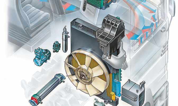
03

Contents
 Modern cooling systems 		                         Intake air and temperature management

 Integrated system—passenger cars              4   Air temperature control
 Integrated system—commercial vehicles         5   for the combustion process in the engine		            27
 Design of a modern cooling module             5   Subsystems of intake
                                                   air temperature management (ATM)		                    28
                                                   Battery temperature management for hybrid vehicles    31
 Cooling: a retrospective view

 Engine cooling with water                     6   PTC auxiliary heaters
 Modern engine cooling                         7
                                                   Design and function                                   33
                                                   Performance and spontaneity                           34
 Cooling systems
                                                   Operational safety                                    35
                                                   Actuation                                             35
 The engine cooling system                     8
                                                   New developments                                      35
 Radiator                                      9
 All-aluminum radiator                        11
 Expansion tank                               12   Diagnostics, maintenance, and repair
 Thermostats                                  13
 Coolant pumps                                14   Coolant, antifreeze, and corrosion protection         36
 Electric coolant pumps                       15   Radiator maintenance                                  37
 Cabin heat exchangers                        16   Bleeding the system when filling                      38
                                                   Typical damage                                        39

 Engine fans
                                                   Electronically controlled cooling
 Visco® fans                                  17
 The electronic Visco® clutch                 18   Coolant temperature level                             42
 Electric radiator fans                       19   Coolant distributor housing                           43
                                                   Coolant control unit                                  44
                                                   Electronic control: Overview                          45
 Other cooling systems
                                                   Controlling the coolant temperature
                                                   when heating is required		                            46
 Oil coolers for engine, transmission,
                                                   Map-controlled thermostat                             48
 and hydrodynamic retarders		                 20
 Power steering cooling                       21
 Fuel cooling                                 21   Technical information		                               50
 Direct charge air cooling                    24
 Indirect charge air cooling                  25
 Cooler for exhaust gas recirculation (EGR)   26
04          Modern cooling systems

Modern cooling systems

Integrated system—                                                     values can be affected by an increased operating temperature,
                                                                       leading to faulty engine control. In addition, in engine variants
passenger cars                                                         such as direct injection, both diesel and gasoline, which gener-
                                                                       ate only a small amount of heat, the cooling system must warm
All of the heat generated by an engine and its dependent sys-          the vehicle occupants in winter and cool them in summer. All
tems must be dissipated. Today, the operating temperature of an        these factors must be considered when developing a thermal
engine is only permitted a small tolerance in order to control oper-   management system. Added to this is the requirement for higher
ation and ambient temperature (engine and interior). Emissions         performance and efficiency in a smaller installation space.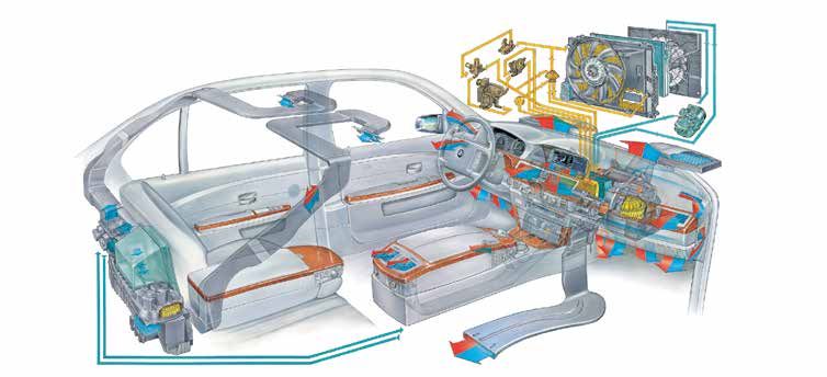
05

                                                                                           1           9           8

                                                                               2

                                                                               3

                                                                               4                                            7

                                                                                                           5   6

Integrated system—                                                      1   Pressure shroud with electrically driven fan

commercial vehicles                                                     2   Power steering cooler

                                                                        3   Air conditioning condenser module
This is a typical example of the current status of thermal manage-
ment in commercial vehicles. We will look at both segments—             4   Module frame
passenger cars and commercial vehicles—below.
                                                                        5   All-aluminum radiator

Design of a modern cooling module                                       6   Transmission oil cooling

                                                                        7   Suction shroud for engine fans
This is a typical example of the current status of a cooling mod-
ule. It consists of the radiator, engine oil cooler, air conditioning   8   Module frame cover
condenser, transmission oil cooler, power steering cooler, and
                                                                        9   Engine oil cooler
radiator/air conditioning condenser fan.
06          Cooling: a retrospective view

Cooling: a retrospective view
Engine cooling with water                                             As engines evolved, a coolant regulator or thermostat was used.
                                                                      The water circulation through the radiator was controlled depend-
                                                                      ing on the coolant water temperature. In 1922, it was described
The temperatures generated during fuel combustion (up to
                                                                      as follows: “The purpose of these devices is to warm up the
2,000°C) are harmful to the operation of the engine. That is why
                                                                      engine quickly and prevent it from cooling down.” We are already
the engine is cooled to operating temperature. The first type of
                                                                      talking about a thermostat-controlled cooling system with the fol-
cooling using water was thermosiphon cooling. The heated,
                                                                      lowing functions:
lighter water rises through a manifold into the upper part of the
cooler. It is cooled by the airstream, sinks to the bottom, and
                                                                      n   Short warm-up time
flows back to the engine. This circuit remains in operation as long
as the engine is running. The cooling was supported by fans—so        n   Operating temperature kept constant
no control was possible. Later, the water circulation was acceler-
ated by a water pump.

Weak points:

n   Long warm-up time

n   Low engine temperature during the cold season

BEHR wind tunnel 1937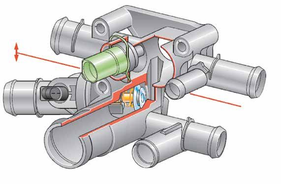
07

MAHLE climatic wind tunnel today

Modern engine cooling                                                    To cool an engine, use is now made of the fact that pressurized
                                                                         water starts to boil not at 100°C but at 115°C to 130°C. So
                                                                         the cooling circuit is under a pressure of 1.0 to 1.5 bar. We are
The thermostat and the resulting “short-circuited” coolant cir-
                                                                         talking about a closed cooling system. For this purpose, the sys-
cuit brought about a crucial improvement in engine cooling. As
                                                                         tem has an expansion tank that is only about half filled. Instead
long as the desired operating temperature of the engine is not
                                                                         of just water, a mixture of water and coolant additive is used as
reached, the water does not flow via the radiator, but passes
                                                                         the cooling medium. We are now talking about coolant that has
back into the engine by a short route. Only when the desired
                                                                         antifreeze properties as well as an increased boiling point and
operating temperature is reached does the thermostat open the
                                                                         protects engine and cooling system components from corrosion.
connection via the radiator. To this day, all systems have featured
this control.

The operating temperature of the engine is of vital importance not
only for performance and consumption, but also for low emissions.

                                                                                                                                  radiator

                             manifold
                                                                               since 1922

                                                                                                                               thermostat

                                                                                                                                   engine
                                                                                                                             water pump

                                                        Around 1910 with water pump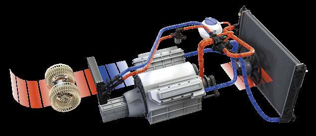
08          Cooling systems

Cooling systems
The engine cooling system                                         The requirements placed on the cooling system are:

                                                                  n   Shorter warm-up phase
With the engine compartment becoming more and more com-
                                                                  n   Rapid cabin heating
pact, housing the components and dissipating the enormous
amounts of heat poses a significant challenge. In order to cool   n   Low fuel consumption
down the engine compartment, high demands are placed on
                                                                  n   Improved component service life
modern cooling systems. As a result, there has recently been
great progress in the field of cooling.
                                                                  All engine cooling systems are based on the following
                                                                  components:

                                                                  n   Radiator

                                                                  n   Thermostat

                                                                  n   Coolant pump (mechanical or electrical)

                                                                  n   Expansion tank

                                                                  n   Lines

                                                                  n   Engine fan (V-belt driven or Visco®)

                                                                  n   Temperature sensor (engine control/display)

                                                                                                                    8

                                              4

                                                                                         5
                                                                      6

                                 3
                                                                                                1   Radiator
     1
                                                                                                2   Coolant pump

                                                                                                3   Radiator fan
                                                                              7
                                                                                                4   Thermostat

                                                   2
                                                                                                5   Heat exchanger

                                                                                               6    Heat exchanger valve (optional)

                                                                                               7    Engine

                                                                                               8    Airflow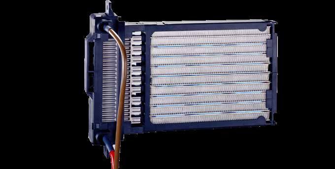
09

Radiator

Radiator                                                            Advantages:

                                                                    n   Precise fitting for easy installation
Engine cooling began in 1905. The combustion temperature in the
                                                                    n   Optimal efficiency
engine at that time was around 600°C to 800°C. Steel radiators
were used around the turn of the century until about 1938; after    n   Tailored to customer specifications (OEM)
that, metal radiators (copper/brass) appeared. Disadvantage: high
weight and limited supply, meaning a high material price.           Typical design

Requirements for the radiator:                                      The oil cooler can also be a separate component of the radia-
                                                                    tor. The individual parts are assembled to give the radiator its
n   High power density
                                                                    shape. The cooling takes place via the cooling fins (core matrix),
n   Adequate strength                                               whereby the air takes heat from the coolant as it flows through.
                                                                    The coolant flows from top to bottom, called downdraft, or from
n   Long-lasting corrosion resistance
                                                                    right to left or vice versa (crossflow). Both variants must have
n   Low manufacturing costs                                         enough time and a sufficiently large cross section to allow the air
                                                                    to cool the coolant effectively.
n   Environmentally sound production

Design:

n   Water tank made of GFP = glass fiber-reinforced polyamide

n   Increasingly from aluminum

Task:

n   To cool the coolant in the engine circuit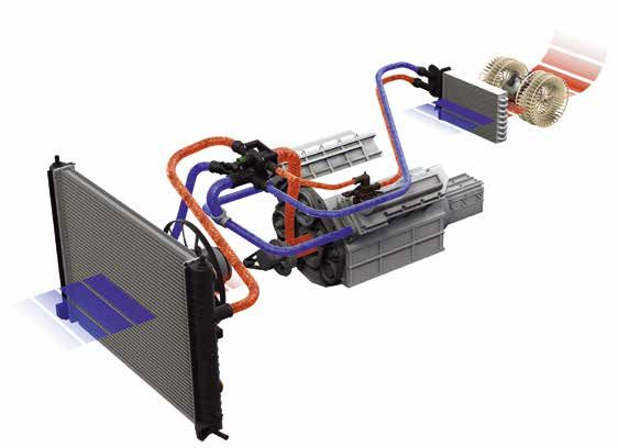
10          Cooling systems

                                        5

                        4                                                                      1   Water tank
                3
           2
                                                                                               2   Oil cooler
     1                                                                      1

                                                                                               3   Seals

                                                                                               4   Cooling fins (core matrix)

                                                                                               5   Side plates

                                                                                              6    Base
                                                               3
                                                         6
                                                                                              7    Cooling tube
                                              7

                                    5

                        6

Designs                                           mechanically joined or brazed. The tech-
                                                  nical performance data for the two pro-
There are two typical designs: brazed and         duction processes is virtually identical.
mechanically joined. Both types are used          However, the mechanically joined version
with downdraft cooling. The first radiators       has a lower weight. It is ultimately up
were equipped with brass water tanks              to the vehicle manufacturers to decide
and later with plastic tanks. Crossflow           which process will be used in series pro-
radiators are 40% smaller than down-              duction.
draft radiators and are used in current
                                                                                              Brazed
passenger cars where a flatter design is          The design of the radiator’s tube/fin
required. The water tank is fastened and          geometry determines its performance.
sealed with corrugated crimped edging             The available installation space in the
developed by MAHLE. Another type of               vehicle must be taken into consideration.
fastening is tab flanging. Downdraft radi-
ators are used in taller passenger cars
(cross-country vehicles, etc.) and com-
mercial vehicles. There are essentially
two different methods for manufacturing
radiators: the components can be either                                                       Mechanically joined
11
All-aluminum radiator
All-aluminum radiator n Recyclable in its entirety
n Transport damage is reduced (overflow nozzle)
As can be seen here, the core depth is considerably reduced
n Different pipe types can be used
in the all-aluminum design. This design helps keep the overall
depth of the cooling module low. For example, the all-aluminum n Round tube offers higher performance with turbulence insert
radiator of the Audi A8 is 11% lighter and has a 20 mm smaller
n Oval tube (offers more space for cooling)
installation depth.
n Flat tube, mechanical production, paneled (even more space
This construction offers the following properties: and only a single row needed)
n The upper base is no longer needed n Flat tube, brazed, without flux (best cooling, fins fit 100%),
but cost-intensive
n The core depth is equal to the radiator depth
n Special aluminum alloy used (core matrix)
n 5% –10% weight reduction
n Temperature 600°C to 650°C then cool down to approx.
n Greater operational stability
130°C (tensions are compensated)
n Burst pressure 5 bar
This comparison shows the difference between a radiator with a that the overall depth is considerably reduced, saving space when
standard base and an all-aluminum radiator. It can be clearly seen installed in a modern cooling module.
Core depth 40 mm, overall depth 63.4 mm Core depth 40 mm, overall depth 40 mm12 Cooling systems
Expansion tank for commercial vehicles
Expansion tank Function
A high coolant temperature leads to a pressure increase in the
To prevent local overheating of the components, the coolant
cooling system as the coolant expands. The coolant is forced into
circuit must be bubble-free. The coolant enters the tank at high
the tank. The pressure in the tank increases. The pressure-relief
speed and exits at low speed (different nozzle diameters).
valve in the cap opens and allows air to escape. When the cool-
ant temperature normalizes, a vacuum is created in the cooling
In comparison, commercial vehicle expansion tanks have three
system. Coolant is sucked out of the tank, which also creates a
chambers and a large volume of water—e.g., a coolant volume
vacuum in the tank. As a result, the vacuum compensation valve
of 8 liters. The expansion tank is designed to absorb expanded
in the filler cap of the tank opens. Air flows into the tank until the
coolant from the coolant circuit. The pressure is reduced by a
pressure equalizes.
valve, and the system pressure is therefore kept at a predefined
value.
Expansion tank for passenger car How an expansion tank works13
Electronically controlled thermostat with wax element
Thermostat Function
When heated above 80°C, the wax filling melts. As the volume
Thermostats control the temperature of the coolant and thus
of the wax increases, the metal container moves on the working
also the engine temperature. Mechanical thermostats have not
piston. The thermostat opens the radiator circuit and simultan-
changed much over the years and are still being installed today.
eously closes the by-pass loop. If the temperature drops below
They function by means of an expanding wax element that opens
80°C, the wax filling solidifies. A return spring pushes the metal
a valve and returns the coolant to the radiator for cooling. The
container back to its starting position. The thermostat closes
thermostat opens at a certain temperature that is predefined for
the supply to the radiator. The coolant flows directly back to the
the system and cannot be changed. Electronically controlled
engine via the short-circuit line.
thermostats are regulated by the engine control unit and open
according to the operating conditions of the engine. Electron-
ically controllable temperature regulators help to reduce fuel
consumption and pollutant emissions by improving mechanical
engine efficiency.
Advantages:
n Reduction of fuel consumption by approx. 4%
n Reduction in pollutant emissions
Open Closed
n Improved comfort (by improving the heating performance)
n Longer engine service life
n Preservation of the flow conditions and
thermodynamic conditions
radiator engine engine
n Demand-oriented temperature regulation
n Very high speed of temperature change
engine
n Lowest overall installed size increase (< 3%) Thermostat with wax element14 Cooling systems
Coolant pump
Coolant pumps
Coolant pumps transport the coolant through the circuit and
increase the pressure. Coolant pumps also undergo technical
innovations, but there are still a large number of passenger cars
and commercial vehicles with belt-driven coolant pumps on the
market. Electronically controlled coolant pumps are the next gen-
eration. These coolant pumps are driven on demand, similar to
the compressor in the air conditioning circuit, allowing an optimal
Timing belt kit with coolant pump
operating temperature to be reached.
Coolant pumps consist of five main assemblies
1 Axial mechanical seal
3
2 Impeller The drive wheel and impeller are mounted on a common shaft.
A mechanical seal seals the pump shaft from the outside. The
3 Housing
rotating movement of the impeller transports the coolant through
4 Drive wheel the cooling system.
5 Roller bearing 5
The service life of a coolant pump is heavily influenced by the
1 following factors:
n Proper installation
2
4
n Care and maintenance of the cooling system
n Coolant quality
n Condition and functional capability of the drive belt and the
connected auxiliary aggregates15
Electric coolant pump
Electric coolant pumps By integrating them into the electrical system, it is possible to
carry out diagnostics on electric coolant pumps. Depending on
the type of drive (combustion engine, hybrid, electric) and sys-
Mechanical coolant pumps, which are driven directly by the
tem, one or more pumps can be installed in the vehicle.
engine, continuously deliver coolant while the engine is running,
even when there is no need for cooling. In contrast, electric cool-
ant pumps and their integrated electronic control are variably
activated according to the required cooling performance. They
can be used as main, minor, or circulation pumps. They operate
independently of the engine and as required.
During a cold start, an electric coolant pump initially pumps no
coolant. This allows the engine to reach its operating tempera-
ture faster. Even when idling or after turning off the engine, an
electric coolant pump can deliver sufficient cooling performance,
as it is not connected to the engine speed. This demand-driven
cooling of the engine lowers the power requirement and thus Electric coolant pump for BMW
reduces friction losses and fuel consumption. Electric coolant
pumps thus help to lower emissions in modern cooling systems.
Electric coolant pumps have a wide range of applications:
Another advantage is that electric coolant pumps can be
installed individually, outside the engine. They are relatively light n Cooling the engine
and—thanks to the brushless design—maintenance-free. With
n Charge air cooling
an operating voltage of 12 to 360 volts, they currently achieve
an output of 15 to 1000 watts. The electric motor of the coolant n Cooling the exhaust gas recirculation
pump is cooled by coolant. The continuously variable control is
n Cooling of drive and battery in hybrid and electric vehicles
achieved by means of a pulse-width-modulated (PWM) signal. In
this way, the delivery volume can be controlled independently of n Transmission cooling
the engine speed, according to the actual demand, and the cool-
n Cooling of various parasitic loads
ant temperature can be kept constant as required by the system.16 Cooling systems
Cabin heat exchangers
Cabin heat exchangers
The heat exchanger supplies heat, which is transported into the
vehicle cabin with the airflow of the blower. If air conditioning is
available, which is usually the case today, a blend of cold and
warm air is produced by the climate control system. Here, all
three factors come together: Heat, cold, and the corresponding
control = air conditioning of the vehicle cabin.
Characteristics of an all-aluminum heat exchanger:
n Fully recyclable
All-aluminum heat exchanger
n Ensures the desired cabin temperature
n Brazed heat exchanger in all-aluminum design
n Reduced space requirement in the vehicle cabin
n High heating performance
n End caps brazed and not clamped
n Installed in the heating box
n Fin-and-tube system
n Gill fields in the fins increase performance
n State-of-the-art, like the radiator: all-aluminum17
Engine fans
The engine fan serves to transport ambient air through the radiator and over the engine. It is driven
by the V-belt or, in the case of an electrically driven fan, by a controlled electric motor. The Visco® fan
is mainly used in commercial vehicles but is also found in the passenger car sector. The engine fan
ensures that a sufficient volume of air flows through to cool down the coolant. With the V-belt-driven
fan, the air volume is dependent on the engine speed. It differs from the condenser fan in that it is
driven continuously. The Visco® fan is controlled by the operating temperature.
Visco® fans Ongoing development resulted in the electronic
Visco® clutch, which has the following properties:
Principle of operation n Continuously variable control
n Control via sensors
Full switch-on point at approx. 80°C. Filled with silicone oil as
drive medium (30–50 ml), switched on by bimetal, and actuated n Controller processes data—e.g., coolant, oil,
via the thrust piece. charge air, engine speed, retarder, climate
This results in demand-based cooling, improved coolant tem-
History
perature levels, lower noise, and reduced fuel consumption. In
Rigid (permanently driven), requires a large amount of energy the passenger car sector, the fans were previously two-piece,
(HP), is noisy, and has a high consumption. On the other hand, with the Visco® clutch and fan wheel bolted together. Today they
electric fans (passenger cars) offer more economical consump- are rolled and therefore no longer repairable.
tion, are low-noise, and have a lower energy requirement. The
development goals were low consumption and less noise—e.g.,
noise reduction through the use of shielded fans.
Around 50 years ago, BEHR developed
the Visco® fan and registered the Visco®
trademark. Since MAHLE acquired a majority
holding in BEHR and the trademark rights
were transferred, Visco® products have
been produced and marketed under the
MAHLE name. Only fans and clutches
of this type produced by MAHLE may
be marketed with the prefix Visco®.
Complete Visco® fan (clutch and fan wheel)18 Engine fans
Visco® clutch
The electronic Visco® clutch
The drive disk and the flanged shaft transmit the power of the
engine. The fan is also securely connected to this component.
Circulating silicone oil ensures the transmission of power by
both assemblies. The valve actuating lever controls the oil circuit
between the reservoir chamber and the working chamber.
The flow of silicone oil from the reservoir chamber to the working
chamber and back takes place between two bores: the return
bore in the housing and the supply port in the drive disk.
The valve actuating lever controls the engine management via
pulses to the solenoid assembly. The hall-effect sensor deter- Visco® clutch
mines and informs the engine management about the current
speed of the fan. A regulator sends a pulsed control current to
the solenoid assembly that controls the valve actuating lever,
which in turn controls the oil flow and oil quantity. The more sil-
icone oil there is in the working chamber, the higher the speed
of the fan. When the working chamber is empty, the fan is in idle
mode and there is a slip of about 5% at the drive.
Fan wheel air duct Electronically controlled Visco®
clutch with fan19
Electric radiator fan with shroud
Electric radiator fans Causes of failure include mechanical damage (crash, bearing
damage, broken guide vane) and electrical faults (contact fault,
short circuit, defective switch/control unit).
In passenger cars, electric fans are mostly used. They are often
deployed as extractor fans, but sometimes also as pressurizing
The electric radiator fan or fans are usually mounted on fan
fans. By allowing a greater flow of air to pass through the engine
shrouds. These have the task of guiding the air flowing through
radiator when the fan is operating, they ensure that the coolant is
the radiator to the fan in a targeted manner and as free from
kept at an optimal temperature under all vehicle operating con-
flow losses as possible. For this reason, the fan shroud is also
ditions. In the front section of the vehicle there are usually other
mounted as close as possible to the radiator.
coolers (e.g., charge air, steering, fuel, condenser) whose media
(air, oil, fuel, refrigerant) are also cooled down by electric fans.
The fan or fans (double fan) are controlled via pressure or tem-
perature switches or a control unit. This allows the fan speed
to be controlled stepwise (switch) or continuously (pulse-width-
controlled) according to the operating conditions. With electron-
ically controlled fans, the control unit is often located near the
fan unit. With the help of a diagnostic tool/oscilloscope, the fault
memory can be read out or the control functionality checked.20 Other cooling systems
Other cooling systems
All-aluminum oil cooler for hydrodynamic retarders
Oil coolers for engine, retarder-
oil reservoir
transmission, and transducer compressed
hydrodynamic retarders air connection
Cooling as well as faster heating of engine oil and transmission
oil cooler
oil (e.g., automatic transmission, retarder) is ensured by built-in or
attached coolers (engine or transmission) in the water tank. The
two main types are tube or disk oil coolers in an all-aluminum or
steel design. to/from
coolant circuit
Advantages:
Retarder with attached oil cooler
n Cooling of oils with a high thermal load
n Oil change intervals are extended;
the service life of the engine is increased
n Low space and weight requirements
thanks to all-aluminum design
n Compact design due to powerful stacked
plates with large-scale surface cooling21
Power steering cooler Fuel cooler
Power steering cooling Fuel cooling
The power steering oil must also be cooled—otherwise, the Fuel cooling is mainly used in diesel engines. The fuel is cooled in
efficiency of the power steering is impaired, and the steering order to lower the inlet temperature at the pump nozzle or com-
becomes either too heavy or too light. mon rail. Otherwise, the high pressure would cause an excessive
increase in fuel temperature, impairing engine performance by
Properties: premature combustion in the combustion chamber.
n All-aluminum with quick-release coupling connections
n Pressure more than 8 bar with an oil inlet temperature
of –40°C to +160°C
n Test pressure 20 bar with a burst pressure of 50 bar22 Other cooling systems
Charge air cooler
Charge air cooling Types:
Air cooled and coolant cooled, direct and indirect
The trends toward increasing engine performance and down-
sizing are leading to an increasing proportion of turbocharged Task:
engines in passenger cars, which means that today’s engines
Increasing the performance of the engine by charging
are generally turbocharged using cooled charge air. The higher
(more combustion air, higher oxygen content)
charge air density achieved in this way increases the output and
efficiency of the engine. However, it is not only the number of
Properties:
turbocharged engines that is increasing, but also—due to the
further required reductions in consumption and emissions—the n Higher dynamic cooling capacity
demands on the charge air cooling capacity. These demands
n Improved engine efficiency due to
can be met by cooling the charge air using coolant instead of air.
the increase in charge air density
However, because of the system costs, this technology has so
far been reserved for the upper passenger car price segment. n Lower combustion temperature,
New developments also make it possible to control the charge resulting in better emissions values
air cooling. This makes it possible to reduce the NOx and HC
n Fewer nitrogen oxides at –40°C to +160°C
emissions, while increasing the effect of the exhaust gas after-
treatment. Aside from improving the cooling capacity, there is a n Test pressure 20 bar with a burst pressure of 50 bar
further requirement for charge air cooling: controlling the tem-
perature of the engine process air by regulating the charge air
cooling. This temperature control is made necessary by the
steadily increasing demands on exhaust gas aftertreatment—the
temperature of the charge air plays an important role here. So
cooling the charge air with coolant also offers decisive advan-
tages when it comes to commercial vehicles.23
The performance of a combustion engine
depends on the amount of fuel burned
1 kg fuel requires 14.7 kg air for complete
combustion in a gasoline engine
Diesel engine >14.67 kg air for 1 kg fuel
Turbocharging combustion engines is therefore
an effective means of increasing performance
Turbocharged engine naturally aspirated engine
Exhaust gas turbocharging
Basics: exhaust gas turbocharging Requirements: an increase in cooling performance
The performance of a combustion engine depends on the In passenger cars, the rising demand for cooling performance
amount of fuel burned. 1 kg fuel requires 14.7 kg air for com- conflicts with the increasingly restricted installation space in the
plete combustion in gasoline engines—this is the stoichiometric vehicle’s front end. Compact charge air coolers still dominate
ratio. Turbocharging combustion engines is an effective means of today. One solution to the problem of the small installation depth
increasing performance. is to enlarge the compact charge air cooler so that it becomes a
flat charge air cooler mounted in front of the radiator, as is stan-
dard in heavy-duty commercial vehicles. Consequently, the use
of this design is increasing. However, this is not possible in many
vehicles because the required installation space has already
been allocated or is no longer available because of other require-
ments—such as pedestrian protection. The conflict between
installation space and power requirements can be resolved with
two new systems: charge air precooling and indirect charge air
cooling.
Charge air ducting when using direct charge air/air cooling (for example)24 Other cooling systems Charge air ducting when using direct charge air/coolant cooling (for example) Charge air precooler By using the new charge air precooler, which is fed with cool- ant from the engine circuit, some of the charge air waste heat is shifted from the charge air cooler to the radiator. Since the additional charge air waste heat, which is produced as a result of the performance increase, can be dissipated through the precooler, the concept of a block-shaped charge air cooler can be retained. The charge air precooler, also a compact cooler, is placed between the turbocharger and the charge air/air cooler. Thanks to the charge air precooling, the performance of an exist- ing concept can be significantly increased. The required overall installed size of a charge air cooler/radiator is 40% to 60% of a charge air/air cooler.
25

                                                                                                                              charge air
      charge air cooler/radiator

                                                                                                                        electric pump

                                                                                                                     low-temperature
                                                                                                                              circuit

      turbocharger

                                                                                                                         main radiator
      electric coolant pump

                                                                                                                     low-temperature
      main coolant circuit                                                                                                   radiator

Coolant circuit in indirect charge air cooling

Indirect charge air cooling                                              Compared with charge air precooling (direct), indirect
                                                                         charge air cooling results in the following positive effects:

The second way of resolving the conflict between installation            n   Significantly reduced charge air pressure loss
space and power requirements is the use of indirect charge
                                                                         n   Improved engine dynamics thanks
air cooling. In the passenger car, this cooling system generally
                                                                             to the lower volume of charge air
consists of a complete coolant circuit that is independent of the
engine cooling circuit. A low-temperature radiator and a charge          n   Higher dynamic cooling capacity
air cooler/radiator are incorporated in this circuit. The charge air’s
                                                                         n   Improved engine efficiency due
waste heat is initially transferred to the coolant and then dissi-
                                                                             to increase in charge air density
pated to the ambient air in the low-temperature radiator. This
cooler is integrated in the vehicle’s front end, where the charge
air/air cooler is located in conventional air-cooled charge air cool-
ing. Since the low-temperature radiator needs significantly less
space than a comparable charge air/air cooler, space is freed up
in the front end. This also means that the bulky charge air lines
from the vehicle front end to the engine are no longer needed.
This significantly simplifies the overall packaging in the front end,
improving the cooling airflow through the engine compartment
accordingly.
26 Other cooling systems EGR coolers of various types Coolers for exhaust gas recirculation (EGR) One way of meeting the new Euro 6 limits for nitrogen oxide emis- sions (NOx) is cooled exhaust gas recirculation (EGR). Some of the primary exhaust gas flow between the exhaust manifold and the turbocharger is extracted, cooled in a special heat exchanger (EGR cooler), and fed back into the intake air. This decreases the combustion temperature in the engine, reducing the formation of nitrogen oxides. The EGR cooler is made of stainless steel or aluminum and has EGR cooler several connections via which hot exhaust gases and coolants can flow into the cooler. After the exhaust gases have been cooled down in the cooler, they leave the cooler and are fed in metered doses to the intake system and thus to the combustion chamber. This leads to a reduction in nitrogen oxide emissions even before reaching the catalytic converter. Pneumatic and/or electric actuators are installed on the EGR cooler to perform the control function. Although the EGR cooler is not a classic wear part, defects due to extreme temperature fluctuations or missing or aggressive coolant additives, for example, can lead to internal or external leaks. Moreover, it is possible that the actuators will fail.
27

Intake air and
temperature management
Air temperature control for                                             Regulation of the charge air temperature is important for exhaust
                                                                        gas aftertreatment by particulate filters and catalytic converters.
the combustion process in                                               Both require a certain minimum exhaust gas temperature for

the engine                                                              optimal operation. In the case of the catalytic converter, this min-
                                                                        imum temperature is identical to its startup temperature, while
                                                                        in the case of the particulate filter it is identical to the regener-
After a cold start and at extremely low outside temperatures while
                                                                        ation temperature required for the combustion of the accumu-
driving, it is advisable to suspend the charge air cooling. The
                                                                        lated soot. When the vehicle is in partial-load operation (urban
engine and catalytic converter then reach their optimal operating
                                                                        traffic, stop and go) these exhaust gas temperatures are not
temperature more quickly, resulting in fewer cold-start emissions,
                                                                        always reached. Even in these cases, emissions can be reduced
mainly hydrocarbons (HC). With a charge air/air cooler, this is
                                                                        by stopping cooling or even heating the charge air, because in
only possible by means of a bypass on the charge air side—
                                                                        any case the temperature of the exhaust gas is increased. Both
involving great expense. With indirect charge air cooling, on the
                                                                        options are most easily achieved by means of indirect charge air
other hand, simple control of the coolant volume flow rate not
                                                                        cooling.
only allows the cooling of the charge air to be suspended, but
also makes it possible to control its temperature. By linking the
coolant circuit for charge air cooling with the circuit for engine
cooling and with intelligent control of the coolant flow rates, indi-
rect charge air cooling can be extended to cover charge air tem-
perature control. Either the hot coolant of the engine circuit or the
comparatively cooler coolant of the low-temperature circuit can
flow through the charge air cooler.

exhaust gas radiator
with bypass
                                                                                                                 charge air cooler/radiator
exhaust                                                                                                                          thermostat
gas

                                                                                                                     electric coolant pump

charge air
                                                                                                                           low-temperature
                                                                                                                                    circuit

main coolant circuit

electric coolant pump
thermostat                                                                                                                 low-temperature
main radiator                                                                                                                       radiator
28 Intake air and
temperature management
Subsystems of intake air Charge air heating
temperature management With ATM, the intake air can be heated in four ways: by dis-
(ATM) continuing charge air cooling or exhaust gas cooling, by discon-
tinuing both, or by heating the charge air. For heating, a partial
Indirect charge air cooling flow of hot coolant is branched off from the engine cooling circuit
and guided to the charge air cooler. In tests with a 2-liter diesel
Charge air cooling increases the air density in the cylinder and unit on an engine test bench with a brake mean effective pres-
reduces the combustion temperature. In ATM, the charge air is sure of 2 bar, the exhaust gas temperatures downstream of the
not cooled by air as usual, but by a liquid coolant, a water-glycol turbine were measured. These measurements were obtained by
mixture as used for engine cooling. The charge air’s waste heat varying the intake air temperatures according to the possibilities
is initially transferred to the coolant and then dissipated to the described above. As a result of interrupting the charge air cool-
ambient air in a low-temperature radiator. ing, the lowest exhaust gas temperature increase was approx.
6°C. If the charge air was heated with the engine coolant (thermo-
Advantages of indirect charge air cooling: stat temperature), which is around 85°C, the exhaust gas tem-
perature downstream of the turbine rose by approx. 16°C. The
n Higher cooling capacity than with
maximum potential obtained from heating is probably 20°C. The
conventional charge air/air cooling
highest increase of approx. 57°C was produced by interrupting
n Higher cylinder volumetric efficiency the exhaust gas cooling (switchable exhaust gas cooler). If this is
due to lower charge air pressure loss combined with heating the charge air, the exhaust gas tempera-
ture can be raised by over 70°C. At a mean effective pressure of
n Shorter response time of the charge air cooler
4 bar, an increase of as much as 110°C is possible.
due to its placement near the engine
Cooled exhaust gas recirculation
It causes a reduction of the oxygen concentration in the cylin-
der, lowering the temperature and speed of combustion. Intake
air temperature management (ATM) is suitable for both high-
pressure and low-pressure exhaust gas recirculation. In high-
pressure exhaust gas recirculation, the exhaust gas is extracted
upstream of the turbocharger, cooled in the exhaust gas cooler,
and then mixed into the charge air. If the intake air temperature
needs to be raised to improve exhaust gas aftertreatment, the
exhaust gas cooler is bypassed. Low-pressure exhaust gas recir-
culation is an option for the future. Here, the exhaust gas is not
extracted upstream, as in the case of high-pressure exhaust gas
recirculation, but downstream of the exhaust gas turbocharger
and also the particulate filter. It is then cooled and mixed with the
charge air upstream of the turbocharger’s compressor.29
Euro 6 and its significance temperature management (ATM) system developed by MAHLE
reduces emissions at the point of origin, supports exhaust gas
aftertreatment, and facilitates the regeneration of the particulate
For diesel passenger cars, Euro 6 requires a further significant
filter. In addition, synergies between the ATM subsystems mean
reduction in emissions compared with Euro 4 and Euro 5 for
that less installed cooling capacity is required than for current
hydrocarbons (HC), nitrogen oxides (NOx), and particulates.
systems, thus saving fuel and installation space.
Temperature control of the engine intake air is becoming increas-
ingly important in order to achieve these goals. The intake air
Diesel passenger car exhaust gas emissions
100
90
80
70
85% 97%
60
50 Euro 1 1992
40 Euro 2 1996
30 Euro 3 2000
20 Euro 4 2005
Euro 5 2009
10
Euro 6 2015
0
CO NOx + HC Particles
Operating principle of intake Reducing emissions
air temperature management NOx: Since NOx formation is exponentially dependent on the
(ATM) combustion temperature, its reduction results in a significant
decrease in NOx: by around 10% for a temperature reduction
The ATM consists of three subsystems: indirect charge air of 10°C; fuel consumption decreases by 0.5%–1%. HC and
cooling, cooled exhaust gas recirculation, and engine cooling. CO: During a cold start, the combustion temperature is usually
These subsystems are linked and controlled in such a way that still low, the combustion is incomplete, and the formation of HC
the intake air can be cooled and heated and the combustion and CO is therefore high. Since the oxidation catalyst has not
temperature raised and lowered. The temperature is lowered by yet reached its operating temperature in this phase, emissions
cooling the charge air and exhaust gases and by adding as many are produced. In certain situations (urban traffic in winter, stop
exhaust gases to the charge air as possible according to the load and go), the combustion and catalyst temperature can drop so
case of the engine and reducing the oxygen concentration in the low, even during normal driving, that HC and CO emissions are
cylinder accordingly. In order to increase the combustion tem- produced. In both cases, the rapid increase in the combustion
perature, the charge air and exhaust gas cooling are suspended, and therefore the exhaust gas temperature caused by the ATM
and the charge air can also be heated. reduces the formation of HC and CO and promotes their conver-
sion in the catalytic converter. The temperature is increased by
stopping the exhaust gas cooling. For this purpose, the exhaust
gas cooler is equipped with an integrated bypass and an elec-
tric resonance control flap. Measurements on a chassis dyna-
mometer on a turbocharged 1.9-liter diesel engine showed an
approximately 30% reduction in HC and CO emissions during
cold starts.30 Intake air and
temperature management
Regeneration of tiated by lowering the soot ignition temperature—e.g., by means
of a fuel additive. A combination of both processes—raising the
the particulate filter exhaust gas temperature and lowering the soot ignition tem-
perature—has certain advantages: the amount of additive can
When the particulate filter is full, the accumulated soot must be be reduced, and the dosing system simplified. However, if the
burned. This also means that the ATM system needs to increase temperature increase generated by the ATM system is combined
the exhaust gas temperature, which is usually below the soot with postinjection, an additional system for filter regeneration is
ignition temperature of 550°C. Soot combustion can also be ini- usually not required.
Energy savings level ground, the charge air cooler can be dispensed with com-
pletely and the full cooling capacity can be made available to the
exhaust gas cooler. Under full load, however, virtually the entire
Different amounts of heat accumulate in the charge air and
cooling capacity must be used for the charge air cooler. By dis-
exhaust gas cooler depending on the engine load. Under partial
tributing the coolant flows according to demand in this way, the
load, where the exhaust gas recirculation rate can be over 50%,
installed cooling capacity and installation space can be reduced
more coolant is required in the exhaust gas cooler than in the
considerably—e.g., by up to 10%.
charge air cooler. At some partial-load points, e.g., 50 km/h on31
Battery temperature the coolant is performed. Thanks to the use of the chiller, the
battery can be operated within the most efficient temperature
management for hybrid window.
vehicles
1
The correct temperature plays a key role for batteries with larger
2
capacities. Therefore, at very low temperatures, additional heat-
3
ing of the battery is required to bring it to the ideal tempera-
4
ture range. This is the only way to achieve a satisfactory cruising
5
range when in “electric driving” mode.
6
To enable this additional heating, the battery is integrated into
a secondary circuit. This circuit ensures that the ideal operating
temperature of 15°C to 30°C is maintained at all times. 7
Coolant, made of water and glycol (green circuit), flows through a
cooling plate integrated into the battery core. At lower tempera-
1 Battery cooler
tures, the coolant can be quickly heated by a heater to reach the
ideal temperature. The heater is switched off if the temperature in 2 Condenser
the battery rises when the hybrid functions are being used. The
3 Module frame
coolant can then be cooled via a battery cooler located in the
vehicle front using the airstream from the vehicle driving forward. 4 Power electronics cooler
5 Radiator
If the cooling by the battery cooler is not sufficient at high outside
temperatures, the coolant flows through a chiller or special heat 6 Fan shroud
exchanger. In it, refrigerant from the vehicle air conditioning sys-
7 Fan
tem is evaporated. In addition, heat can be transferred from the
secondary circuit to the evaporating refrigerant in a very compact
space and with a high power density. An additional recooling of Cooling module for hybrid vehicle
Coolant- and refrigerant-based circuit (or indirect battery cooling)
coolant circuit
compressor
battery cooler
cooling plate
evaporator
condenser
chiller
battery
refrigerant circuit heater32 PTC auxiliary heaters PTC auxiliary heaters Thanks to the high efficiency of modern direct-injection engines, any problems. PTC elements are nonlinear ceramic resistors. both diesel and gasoline, the engine waste heat is often not suf- PTC stands for positive temperature coefficient, which means ficient to quickly heat up the cabin on cold days nor to produce that the electrical resistance increases with the temperature of comfortable temperatures during urban driving and in stop- the element. However, this is not exactly true, because at first and-go traffic. Driving safety is also impaired, as the windows it drops as the temperature rises. The resistance characteristic can fog up. To cover the shortfall in heating capacity, MAHLE curve has a negative temperature characteristic in this range. is developing three types of auxiliary heater: electric PTC auxil- The negative temperature characteristic changes to a positive iary heaters and CO2 heat pumps for spontaneous heating of the one only when the minimum resistance is reached. This means supply air and exhaust gas heat exchangers for faster heating of that as the temperature continues to rise, the resistance first the coolant. The coolant heating increases the performance and drops slowly, then increases sharply from around 80°C until the spontaneity of the conventional heating system and also shortens PTC brick absorbs practically no additional current. At this point, the engine’s cold start phase. The heat pumps operate using the when no air is flowing through the PTC heater, the surface tem- new CO2 air conditioning system. With the auxiliary heaters men- perature of the PTC brick is about 150°C and that of the metal tioned, national and international standards can be met without frame approximately 110°C.
33

Design and function                                                    This keeps the package requirements to a minimum. When out-
                                                                       side temperatures are low and the engine is cold, only cold air,
                                                                       or air slightly heated by the heat exchanger, flows through the
The PTC heater consists of several heating elements, a mounting
                                                                       PTC heater initially. The temperature and resistance of the heat-
frame, an insulating frame, and the relays or power electronics.
                                                                       ing elements are low, but the heating performance is high. When
The heating elements are composed of PTC ceramic bricks,
                                                                       the conventional heater responds, the air temperature and resis-
contact sheets, terminals, and aluminum corrugated fins. The
                                                                       tance increase and the heating performance decreases accord-
corrugated fins increase the heat-emitting surface of the contact
                                                                       ingly. At the surface temperature of a PTC heater, with warm
sheets. To increase the air-side heat transfer, the fins have slits
                                                                       25°C air flowing through it, a volume flow of 480 kg of air per
known as “gills.” Thanks to the improved heat transfer, the exces-
                                                                       hour is achieved. The heating network reaches a mean tempera-
sive increase in cut-in current can be significantly reduced in
                                                                       ture of 50°C at this air temperature.
comparison with auxiliary heaters featuring fins without gills. This
has the advantage that individual PTC strands can be switched
on more frequently—i.e., the heater can be operated with a
higher overall output. The production know-how for these gills
comes from radiator production. The auxiliary heater is located
in the air conditioning system in the airflow directly behind the
conventional heat exchanger, a coolant–air heat exchanger.
34 PTC auxiliary heaters
Performance and spontaneity Test example
A different nominal resistance can be selected for the PTC The vehicle was cooled down to an oil sump temperature of
brick, which will alter the current consumption and performance –20°C overnight. It was then driven in the climatic wind tunnel for
accordingly. A low nominal resistance allows a high heating 30 minutes in third gear at a speed of 32 km/h, which is a realistic
performance during operation. The output of a PTC heater is average speed for urban traffic. After 20 minutes, the mean tem-
between 1 and 2 kW. At 2 kW, the power limit of the 12 V net- perature in the cabin with a PTC heater reached 18°C; without
work (150 A at 13 V) is reached. Higher outputs would be pos- it, the temperature only reached 10°C. With a PTC heater, the
sible with a 42 V electrical system. Because of its low mass and “comfortable temperature” of 24°C was reached after 30 min-
the fact that the electrically generated heat is transferred directly utes; without it, it took over 50 minutes to reach this temperature.
to the airflow without any detours, the PTC heater responds
almost immediately. This high spontaneity is the characteristic
feature of the PTC auxiliary heater. As the engine reaches oper-
ating temperature more quickly as a result of the additional load
on the generator, the conventional heater also responds more
quickly. This additional heating capacity is around two-thirds of
the capacity of the PTC heater. In practice, this heating capac-
ity can be assigned to the PTC heater. The output of the PTC
heater of the 220 CDI E-Class model is 1.6 kW. The PTC heater
is integrated in the heating and air conditioning module directly
downstream of the conventional heat exchanger.
1 Evaporator
2 Heat exchanger
3 PTC auxiliary heaters
1 2 335
Operational safety output of the PTC heater is reduced at the higher discharge
temperatures reached by the heat exchanger. Power electronics
allow the PTC heater to be controlled in several stages or in a
The characteristic resistance curve of the PTC bricks prevents
continuously variable manner, so that it can be adapted to the
the PTC heater from overheating. The temperature on the sur-
required heating performance or the available electrical output.
face of the metal frame is always below 110°C. In addition, the
Control This means that the electricity provided by the electrical system
in every situation can always be optimally utilized for auxiliary
heating. In addition to protection against overvoltage, short cir-
The PTC heater is controlled either externally with relays or by
cuit, and reverse polarity, the power electronics with high func-
means of an integrated control system with power electronics.
tionality include overload protection for each stage, protection of
With relay control, the vehicle manufacturer determines which
the printed circuit board against overheating, and voltage mon-
and how many stages are switched on. The control system inte-
itoring. The high-functionality control system can be diagnosed
grated in the auxiliary heater distinguishes between minimum
by means of an EPROM and thus allows variants to be stored
and high functionality. At minimum functionality, the stages are
(EPROM = erasable programmable read-only memory).
switched on individually. The power electronics protect the aux-
iliary heater from overvoltage, short circuit, and reverse polarity.
No diagnostics functionality is provided with this control system.
Up to eight stages are possible with stepped control. The PTC
auxiliary heater used in the E-Class has seven stages. The con-
trol is dependent on the power balance and auxiliary heating
requirements—i.e., the desired thermal comfort. In the case of
high-functionality control, the power electronics are controlled
steplessly, for example, via the vehicle’s LIN or CAN bus.
New developments n Stepped or linear control via relay or control electronics
n High spontaneity and high efficiency
The new generation of PTC auxiliary heaters differs from the pre-
n Modular design allows optimal adaptation to
vious ones in that they are lighter, have a lower pressure drop
the available installation space in the vehicle
(reduces the blower capacity), and lower manufacturing costs.
n Absolutely safe to operate, no danger to adjacent
Technical characteristics: components because of inherent temperature
limitation (PTC characteristic)
n Electric auxiliary heater; output 1–2 kW
n Only small increase in required blower capacity
n Heat source: self-regulating PTC ceramic bricks,
due to low pressure loss
max. temperature on the surface of the ceramic 150°C
when no air is flowing through the heating network
n Excellent heat transfer thanks to corrugated fin
technology with low pressure drop in the supply air36 Diagnostics, maintenance,
and repair
Diagnostics, maintenance,
and repair
Coolant, antifreeze, the engine to overheat. Since glycol has
a very high boiling point, the boiling point
and corrosion of the coolant can be increased to as high
protection as 135°C by using the correct mixing pro-
portion. This is why a sufficient amount of
antifreeze is important even in warm coun-
Coolant is the generic term for the cooling
tries. The manufacturer’s recommendation
fluid in the cooling system. Coolant pro-
should always be followed, a typical com-
tects against frost, rust, and overheating,
position could be 40%/60% or 50%/50%
while providing lubrication. Its task is to
with the use of inhibited water (drinking
absorb the engine heat and dissipate it via
water quality).
the cooler.
The coolant and additives are subject to
The coolant is a combination of water
a certain degree of wear, so a portion of
and antifreeze (glycol/ethanol), mixed
the additives will be used up over time.
with various additives (bitter substances,
If, for example, the corrosion protection
silicate, antioxidants, foam inhibitors) and
additives are used up, the coolant will turn
colored. The bitter substances are added
Used/new coolant brown. For this reason, some vehicle man-
to prevent the coolant from being drunk
ufacturers prescribe a coolant replacement
accidentally. Silicates form a protective
interval. However, the cooling systems of
coating on the metal surfaces and prevent
newer vehicles are increasingly filled with
limescale deposits, among other things.
long-life coolants (e.g., VW G12++/G13).
Antioxidants prevent components from
Under normal circumstances (if there is no
becoming corroded. Foam inhibitors stop
contamination), no coolant changes are
the coolant from foaming. Glycol keeps
needed (VW) or are only necessary after
hoses and seals supple and raises the
15 years or 250,000 km (newer Mercedes
boiling point of the coolant.
models). In general, the coolant should be
changed in case of contamination (oil, cor-
The mixing proportion of water to anti-
rosion) and in vehicles not filled with long-
freeze should be 60:40 to 50:50. This
life coolants. It is essential to follow the
usually corresponds to antifreeze protec-
vehicle manufacturer’s instructions with
tion from –25°C to –40°C. The minimum
regard to the specifications, replacement
mixing proportion should be 70:30 and the
interval, mixing proportion, and miscibility
maximum mixing proportion 40:60. Further
of the antifreeze.
increasing the antifreeze proportion (e.g.,
30:70) does not lower the freezing point
Coolant must not get into the groundwater
anymore. In contrast, undiluted antifreeze
or be discharged via the oil separator. It
already freezes at around –13°C and does
must be collected and disposed of sep-
not dissipate sufficient engine heat at tem-
arately.
peratures above 0°C. This would cause37
Radiator maintenance radiator may be the cause of an excessively high engine tem-
perature. In this case, flushing with warm water (>50°C) is rec-
ommended and all parts carrying coolant (heat exchanger, cylin-
Cleaning with the steam jet at low pressure (from inside to out-
der head, etc.) should be replaced in addition to the radiator. The
side) is an option, as with condensers. Reduced compressed air
degree of contamination and the vehicle manufacturer’s specifi-
can also be used for external cleaning.
cations thus determine the process and the flushing medium to
be used. In any case, it is important to note that, because of their
Flushing the cooling system
design (e.g., flat tube), not all components of modern cooling
systems can be flushed and therefore will need to be replaced.
If the coolant is contaminated, the coolant must be drained and
the cooling system flushed.
This applies in particular to the following components:
Contamination may include: n Thermostat
n Oil (defective cylinder head gasket) n Radiator
n Rust (internal engine corrosion) n Electric valves
n Aluminum (internal radiator corrosion) n Filler cap
n Foreign matter (additives/sealing agents) n Heat exchanger
n Foreign particles (defective coolant pump)
If the coolant level in the expansion tank is no longer visi-
ble because of contamination (oil, rust), the tank must also be
Depending on the contamination level, the cooling system should
replaced. The thermostat and the filler cap should always be
be cleaned with warm water or with a special flushing agent.
replaced. When using special cooling system cleaners, care
Depending on the vehicle manufacturer and symptom, there
must be taken to ensure that these do not attack sealing ma-
are various procedures for flushing. For example, in the event of
terials or get into the groundwater and are not discharged via the
rust-brown discoloration of the coolant and heating performance
oil separator. The cleaning agents must be collected together
issues, Audi prescribes flushing with a special flushing agent. If
with the coolant and disposed of separately. After flushing, the
multiple flushing processes are carried out, the thermostat must
system must be refilled with coolant (observe specification and
be removed and the heating performance measured before and
mixing proportion) according to the vehicle manufacturer’s speci-
after flushing. Opel advises—e.g., for the Corsa B, Vectra B,
fications, bled, and checked for function and leaktightness.
and Omega B models up to model year 1997—that a cloggedYou can also read