USER AND MAINTENANCE MANUAL - TM 2 STROKE 2010 85/100/125/144 cc. ENGLISH - TM Racing
←
→
Page content transcription
If your browser does not render page correctly, please read the page content below
USER AND
                                                                                                          MAINTENANCE
                                                                                                            MANUAL

                                                             SERIART - Fabriano (AN) - www.seriart.com
                                    Published and printed by SERIART

                                                                                                         TM 2 STROKE 2010
                                                                                                         85/100/125/144 cc.
                                                                                                                           TM RACING
                                                                                                                        USES and ADVICES

ENGLISH   97045.10   TM-06 (ed. 03/10)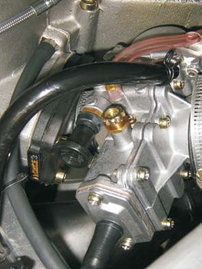
ENGLISH 2
IMPORTANT
 YOU ARE ADVISED TO READ THIS MANUAL CAREFULLY BEFORE USING YOUR MOTO TM.
 IT CONTAINS A LOT OF INFORMATION AND ADVICE THAT WILL MAKE THE USE AND MAINTENANCE OF THE
 MOTORCYCLE MUCH EASIER AND SAFER.

 IT IS IN YOUR SPECIFIC INTEREST TO PAY PARTICULAR ATTENTION TO THE WARNINGS INDICATED IN
 THE FOLLOWING WAY:

      DANGER
 FAILURE TO COMPLY WITH THESE WARNINGS RISKS LIVES!

      WARNING
 FAILURE TO COMPLY WITH THESE WARNINGS COULD CAUSE DAMAGE TO PARTS OF THE MOTORCYCLE
 OR MAKE IT UNSAFE FOR USE.

                        Please make note of your motorcycle’s serial numbers in the boxes below.
When you must contact TM for spare parts, updating requests or to signal problems, indicate the model, cylinder capacity, year of
                       manufacture and most of all the frame number and the engine serial number.

                                FRAME NUMBER

                                ENGINE NUMBER

                                KEY NUMBER

                                STAMP OF THE AUTHORISED DEALER

     TM reserves the right to carry out changes without forewarning. The specifications can change from country to country.
                                  All indications are valid subject to spelling and printing errors.

                                                               3                                                   ENGLISH
Dear TM customer,

  We would like to congratulate you for having chosen a TM motorcycle.

  Your TM is a competitive and modern motorcycle that will surely give you a lot of satisfaction if you treat it
  according to the provisions contained in this manual. Before starting up your TM motorcycle for the first
  time, you must read this manual carefully so as to understand the regulations for use and the features
  of your new motorcycle.
  Only in this way will you know how to adjust the motor cycle, and to adapt it in the best way possible
  to your personal characteristics and how to protect yourself from injury. This manual also contains
  important information regarding the maintenance of your new motorcycle.
  This manual is based on the most recent information concerning the product that was available on going to print.
  Further variations owing to succesive constructive developments of the motorcycle are however possible.
  This manual is an integral part of the motorcycle, it must be given to the customer at the time of purchase and
  must remain with the motor cycle whenever it is re-sold.

  Please note that the operations marked with (A) in the “Frame and Engine Maintenance” chapter must be carried
  out by a TM.specialised workshop. If these maintenance operations should be necessary during competitions,
  they must be carried out by a qualified mechanic.

  For your safety, only use TM original spare parts and accessories.
  TM does not assume any responsibility for the use of other products and for damage deriving from
  them.

  We advise you to respect the running in period, inspection periods and established maintenance periods scru-
  pulously. Only full compliance with these regulations will lengthen the life of your motorcycle. Overhauls and
  repairs must only be carried out by a specialised TM workshop.
  For any information or requests contact a specialised TM workshop, which is backed by the TM importer.
  Please remember that a lot of technical data and information regarding TM motorcycles is available at: www.
  tmracing.it.

  Motorcycling is a marvellous sport that you will be able to enjoy with your TM motorcycle.
  Always remember to respect the environment and other people. Always use the motorcycle with caution, it is in
  everybodys interest to safeguard the future of our sport.

  Enjoy yourself with your TM motorcycle!

                                          TM RACING S.p.A.
                                     Via Fano 6 - 61100 PESARO
                                               ITALY

  TM RESERVES THE RIGHT TO CHANGE OR TO EXECUTE MODIFICATIONS AS IT DEEMS NECESSARY
                                          .

ENGLISH                                                  4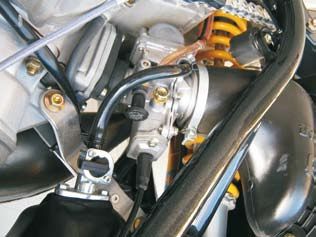
IMPORTANT ADVICE REGARDING
   THE LEGAL WARRANTY AND THE
      COMMERCIAL WARRANTY
TM sport motorcycles are designed and constructed in a manner to support the stress that may be
verified in normal road and competition use.
Competition motorcycles are in compliance with the regulations of the categories actually in force
at the most important international motorcycling federations.

The scrupulous compliance with the established inspections, maintenance and tuning of the engine
and chassis part of the motorcycle, indicated in the user manual, is indispensable for correct fun-
ctioning and to prevent premature wear of the parts of the motorcycle itself.
Incorrect tuning of the engine or of the chassis can also jeopardise one’s own safety and that of
others.

The maintenance operations established in the “Maintenance and Lubrication” table must be carried
out by a specialised TM workshop at the envisioned dates, otherwise any warranty rights will be
forfeited.
When you must contact your TM Dealer for spare parts, updating requests or to signal problems, indicate
the model, cylinder capacity, year of manufacture and most of all the frame number and the engine serial
number.

Fuels and lubricants must be those established in the user and maintenance manual and must be
used as per maintenance programme. Products of other brands can be used as long as they have
the equivalent specifications.

In cases of direct and consequent damage caused by tampering or modifications to the motorcycle,
no legal warranty claim can be asserted.

The use of the motorcycle in extreme conditions, for example on muddy and very wet ground, may
lead to greater than average wear of components, such as transmission components or the brakes.
It is therefore possible that maintenance or replacement of some parts is necessary before the limit
normally envisioned by the maintenance programme.

MX AND SMX MODELS CANNOT BE USED ON PUBLIC ROADS.
The 125 and 144 models in the END, SMR and SMM versions can be used on roads only in the
unvaried type-approved version (reduced). Without this power limitation (i.e. reduced) these
models can only be used off-the-road, but not on public roads.
The END models have been designed for off-the-road resistance competitions (Enduro) and are
not suitable for Motocross.
The 85 and 100 models cannot be used on roads.

                                                     5                                                 ENGLISH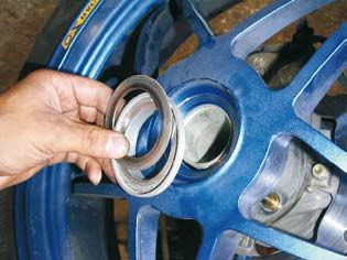
INDEX
                                                                                                                                                                                                      INDEX

                                                                                                    Page                                                                                                             Page
POSITION OF SERIAL NUMBER ................................................... 7                                   Adjustment of chain tension (SMM) .................................................. 42
Frame number ................................................................................... 8                Chain maintenance ............................................................................ 42
Engine number ................................................................................... 8               Chain wear ........................................................................................ 43
OPERATING CONTROLS ................................................................ 9                             Basic indications for TM disc brakes ................................................ 43
Clutch lever AJP pump .................................................................... 10                     Front brake NISSIN pump (END/MX) ................................................ 44
Clutch lever BREMBO pump .............................................................. 10                        Front brake BREMBO radial pump (SMR/SMM/SMX) ...................... 45
Front brake lever NISSIN pump ...................................................... 10                           Check front brake pads ..................................................................... 45
Front brake lever BREMBO radial pump ............................................ 10                              Replacement of front brake pads ..................................................... 46
Electronic digital tachometer ............................................................. 11                    Modification of rear brake pedal base position .................................. 47
Engine stop switch (MX/SMX) ........................................................... 11                        Check rear brake fluid level .............................................................. 47
Combination switch (END/SMR/SMM) ............................................. 12                                 Top-up rear brake fluid ...................................................................... 47
Maps selection switch ......................................................................... 12                Check rear brake pads ...................................................................... 48
Fuel filler cap .................................................................................... 13           Replacement of rear brake pads ....................................................... 48
Fuel tap ............................................................................................. 13         Disassembly and assembly of the front wheel .................................. 48
Choke command (cold starter) .......................................................... 13                        Disassembly and assembly of the rear wheel (all except SMM) ....... 49
Idle speed adjustment command ..................................................... 13                            Disassembly and assembly of rear wheel (SMM) ............................. 50
Gear shift pedal ................................................................................. 14             Check spoke tension ......................................................................... 50
Kickstart pedal .................................................................................... 14           Tyres, tyre pressure .......................................................................... 51
Brake pedal ........................................................................................ 14           Check adjustment of magnetic sensor for tachometer ..................... 51
Side stand .......................................................................................... 14          Battery ............................................................................................... 52
Side stand fixing for off-road routes .................................................... 15                     Battery charge .................................................................................... 52
Ignition switch ..................................................................................... 15          Standard headlightd (END/SMR/SMM) ............................................. 53
Fork adjustment in compression ........................................................ 15                        Halogen light (END/SMR/SMM) ....................................................... 53
Fork adjustment in rebound .............................................................. 16                      Halogen light (END/SMR/SMM) ........................................................ 53
Shock absorber adjustment in compression ...................................... 16                                “Ciclops” optional headlight (END/SMR/SMM) ................................		54
Shock absorber adjustment in rebound                           ......................................... 17       Standard rear light ............................................................................. 54
Steering lock         .................................................................................. 18       LED rear light .................................................................................... 55
ADVICE AND GENERAL RECOMMENDATIONS FOR                                                                            Direction indicator lamp (END/SMR/SMM) ....................................... 55
COMMISSIONING THE MOTORCYCLE ......................................... 19                                         Cooling ............................................................................................. 56
Indications for first start-up                .......................................................... 20       Check coolant level .......................................................................... 57
Running in instructions ................................................................... 20                    Emptying, filling and bleeding of the cooling system ........................ 57
INSTRUCTIONS FOR USE .............................................................. 21                            Replacement of exhaust silencer packing material ........................... 57
Check before every start-up                     ........................................................ 22       Cleaning the air filter ......................................................................... 58
Cold engine start            ........................................................................... 23       Hydraulic clutch AJP pump ............................................................... 59
If the engine is “flooded”              ................................................................ 24       Hydraulic clutch BREMBO pump ....................................................... 59
Bike starting ..................................................................................... 24            Bleeding hydraulic clutch ................................................................... 60
Shifting gear, accelerating, slowing down                           .................................... 24       Throttle cable command adjustment .................................................. 60
Braking ........................................................................................... 26            Notes on the carburettor ................................................................... 60
Stopping and parking ..................................................................... 26                     Basic indications regarding carburetor wear .................................... 61
Fuel ................................................................................................... 27       Check fuel level (float height) ........................................................... 62
MAINTENANCE AND LUBRICATION TABLE ................................. 29                                            Emptying the carburetor float bowl .................................................... 63
FRAME AND ENGINE MAINTENANCE ........................................... 35                                       Check engine oil level ........................................................................ 63
Check steering bearings and play adjustment                               .............................. 36       Engine oil .......................................................................................... 64
Telescopic fork vent screws                    ......................................................... 37       Change engine oil .............................................................................. 64
Cleaning telescopic fork dust scraper ............................................. 37                            Inspection of the reed valve ............................................................... 64
Basic calibration of the chassis on the basis of pilot weight ........... 38                                      TROUBLESHOOTING ...................................................................... 65
Shock absorber calibration and spring check                             ................................ 38       CLEANING ........................................................................................ 67
Establishing rear shock static lowering                         ........................................ 38       PRECAUTIONS FOR WINTER USE ................................................ 67
Establishing rear shock lowering in running order                               ........................ 39       STORAGE ......................................................................................... 67
Check telescopic fork basic calibration                        ......................................... 39       Start-up after seasonal pause ........................................................... 67
Variation of telescopic fork preload                      .............................................. 39       TECHNICAL DATA - ENGINE ......................................................... 68
Replacement of fork springs                   .......................................................... 40       CARBURETOR SETTINGS .............................................................. 70
Variation of rear shock spring preload                        .......................................... 40       ENGINE TIGHTENING TORQUES .................................................. 71
Rear suspension mechanical linkage ............................................. 40                               TECHNICAL DATA-CYCLE PART .................................................... 72
Check chain tension ......................................................................... 41                  ALPHABETIC INDEX ....................................................................... 74
Adjustment of chain tension (all models except SMM) ..................... 41                                      WIRING DIAGRAM .............................................................. appendix

ENGLISH                                                                                                       6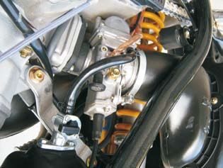
POSITION
OF SERIAL
NUMBER

    7       ENGLISH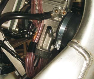
POSITION OF SERIAL NUMBER

 FRAME NUMBER

The frame number is embossed on the right side of the steering metal
tube. Make note of this number in the appropriate space on page 3. In
the END, SMR, SMM models, the serial number is also stated on a plate
positioned on the left hand side. See photo.

The frame number for models 85/100 Junior is on the right-hand side
of the head tube.                                                           1

                                                                            1

ENGINE NUMBER

The engine number is engraved on the back side of the engine. Make
note of this number in the appropriate space on page 3.

                                                                            1

ENGLISH                                                        8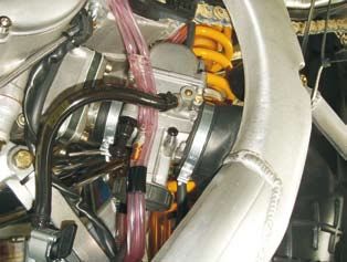
OPERATING
CONTROLS

    9       ENGLISH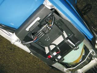
OPERATING CONTROLS
CLUTCH LEVER AJP pump
The clutch lever (1) is mounted on the left of the handlebar. The position
of the clutch lever, with respect to the handlebar grip, can be varied
using the adjustment screws (A) (see maintenace operation).
The adjusting screws (B) are used to adjust the pump after having adju-
sted the lever position and to ensure the correct freeplay.
CLUTCH LEVER BREMBO PUMP
2
The Brembo clutch pump is fit on request.
The clutch lever (2) is located on the left side of the handlebar.
With this option, to adjust the clutch lever distance from the handlebar
grip (see maintenance operation), you have to turn the adjustment knob
(3).
Rotate clockwise to increase the distance or counterclockwise to de-
crease the distance.
3
FRONT BRAKE LEVER NISSIN pump (END/MX)
The distance of the front brak lever (5) from the handlebar grip can be
adjusted through the adjustment screw (C). Loosen the lock nut (6) and
turn the screw clockwise to increase the distance, anticlockwise to re-
duce the distance. Re-tighten the lock nut (6). (see “Frame and Engine
Maintenance” chapter”).
C
4
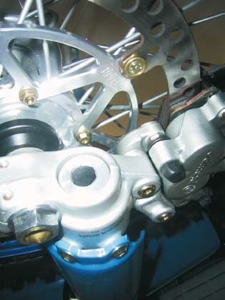
FRONT BRAKE LEVER BREMBO RADIAL pump
(SMR/SMM/SMX)
5
The front brake pump lever (5) is located on the right side of the handle-
bar and activates the front wheel brake. The distance of the brake lever
from the handlebar grip can be adjusted through the adjustment knob
(D) (see “Frame and Engine Maintenance” chapter)
D
ENGLISH 10OPERATING CONTROLS
Electronic digital tachometer
See picture (1). It is used on the END/SMR/SMM models. t has a wide
backlit display and four pilot lights.
In the top there are the left indicator pilot light (2) , the low beam pilot light
(3), the high beam pilot light (4) and the right indicator pilot light (5).
Inside the display you find the tachometer (6), the trip odometer (7) and
the total kilometers odometer (8).
In the bottom there are two buttons, “SET” (9) and “MODE” (10).
The instrument unit is the Kmh but it can be easily changed in Mph in
the following way: press and hold the “SET” button, while holding it press
once the “MODE” button.
Repeat the same operation to switch back to Kmh.
The trip odometer can be reset by holding pressed the “SET” button
once for 4 seconds.
The total kilometres odometer resets automatically when reaching the 5
limit of 99999 Km or Miles.
The SMR and SMM models only are supplied with a separate battery
for using the speedometer while the engine is OFF. This is under the
saddle.
D
ENGINE STOP SWITCH (MX/SMX)
The engine stop switch is found near the clutch piston.
The engine is shutdown using the engine stop switch (1): when it is ac-
tivated a shortcircuit is caused in the ignition, which no longer supplies
voltage to the spark plug.
Press the button until the engine switches off and then release.
1
11 ENGLISHOPERATING CONTROLS
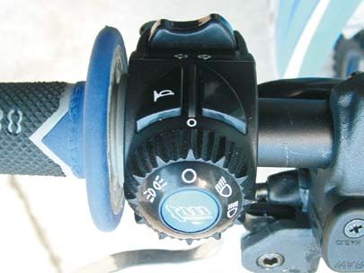
COMBINATION SWITCH WITH BACKLIT DIGITAL
ELECTRONIC SPEEDOMETER
(END/SMR/SMM)
This command (1) is located near the handlebar left grip.
The use of the switch is very easy.
When the symbol (3) on the rotating ring is aligned with the symbol (4)
on the switch body, lights are switched off.
To switch the lights on, turn the ring (2) counterclockwise until the symbol
(5) is aligned with the symbol (4).
Operate in the same way to switch on the low beam (7) and the high
beam (6).
Press the button (8) to activate the horn.
Press the rocker switch (9) on the left to activate the left hand indicator
and on the right to activate the right hand indicator.
Press button (10) to switch off.
The OFF button (10) on the SMR and SMM models is disabled.
10
MAPS SELECTION SWITCH
Some models are equipped with a central control unit with double map-
ping that can be selected using the button positioned on the left side
of the handlebar. Map 1 corresponds to an aggressive map, Map 2 to
a soft map.
10
ENGLISH 12OPERATING CONTROLS
fuel fillER cap
The fuel fill cap is found on top of the tank.
Open: turn the cap in an anti-clockwise direction
Close: place the cap on the inlet well and tighten it in a clockwise di-
rection.
Position the tank’s open vent pipe (1) preventing bends or crushing and
making sure that it is inserted correctly.
FUEL TAP
The tap is located on the left hand side of the tank base.
OFF On the OFF position, the fuel tap is closed.
ON On the ON position, the fuel tap is open.
When the motorcycle is used, turn the tap to the ON position.
In this way the fuel flows to the carburetor and the tank empties
up to reserve.
RES On the RES position, the reserve is used. After having filled up
the tank, do not forget to move the tap back to the ON position. 1
Tank capacity (all models)............ 8.5 Lt. + reserve 1 Lt.
CHOKE COMMAND (COLD starter)
This command is located on the carburetor.
For MIKUNI carburetors (85cc-100cc) and KEIHIN carburetors (125cc-
144cc)
By extracting the choke knob (1) as far as possible, a passage is opened
in the carburetor, through which the engine can suck additional fuel. In
this way, a “rich” air-fuel mix is obtained. This is necessary for starting
the engine when it is cold.
To disconnect the command, push the choke knob inwards to its original
position. 1
IDLE SPEED ADJUSTMENT COMMAND
This control is on the left-hand side of the carburettor for both models.
Turning the idle needle screw increases or decreases the engine’s idling
speed.
Turn it clockwise to increase the idling speed or anticlockwise to de-
crease it.
The idling speed, with the engine warm, must be between 1,400 and
1,600 rpm.
The idling control for the MIKUNI carburettor (models 85/100) features
a lock-nut. You need to undo this lock-nut (1) before turning the screw
(2).
Remember to tighten the lock-nut when you have made the
adjustment.
13 ENGLISHOPERATING CONTROLS
gear shift pedal
The gear shift pedal is positioned on the engine left side. The position
of the gears is indicated in the illustration. The neutral is between the
first and second gears.
1
KICKSTART PEDAL
The kickstart pedal is positioned on the right side of the engine. The
upper part is turned outwards to start-up the engine and replaced inside
as soon as the engine is running.
1
BRAKE PEDAL
The brake pedal is positioned in front of the right foot rest. The basic
position can be adjusted on the basis of the position of the saddle (see
maintenance operations).
1
SIDE STAND
Push the side stand to the floor using the foot and rest the motorcycle on
it. Pay attention that the ground is solid and the position stable.
1
ENGLISH 14OPERATING CONTROLS
SIDE STAND FIXING FOR OFFROAD ROUTES
If you drive the motorcycle off-road, the closed side stand can be addi-
tionally fixed using a rubber band (2).
10
IGNITION SWITCH
In the SMR and SMM models an ignition key is added on the left side
of the dashboard.
By turning the key clockwise, the electric circuit is closed and you can
press the kickstart pedal up the engine.
Turn the key anticlockwise to turn off the engine.
10
FORK ADJUSTMENT IN compression
The hydraulic brake system determines the behaviour of the fork in the
in compression stroke. The degree of hydraulic dampening in compres- 4
sion can be adjusted on the basis of pilot preferences and/or hardness
of the spring installed.
MARZOCCHI USD FORK
There is an adjusting screw (4) on the fork cover. Operate using a
screwdriver. Turning the screw clockwise the dampening increases,
turning it anticlockwise the dampening decreases. A total of 28 clicks
Never turn the side screw (5). 5
PAIOLI USD FORK
Remove the rubber hood (1) situated in the lower part of the fork leg and
turn the adjustment screw (2) using a screwdriver. By turning the screw
clockwise, dampening increases, turning it anticlockwise the dampening
decreases. A total of 26 clicks are available.
OHLINS USD FORK
1
There is an adjusting screw (3) at the base of the fork foot. Operate using
a screwdriver. Turning the screw clockwise the dampening increases,
turning it anticlockwise the dampening decreases. A total of 20 clicks
are available.
2
WARNING
3
BEFORE STARTING IT IS ADVISED TO TIGHTEN THE ADJUSTER FROM THE
STANDARD POSITION TO THE “TOTALLY CLOSED” POSITION AND COUNT
THE NOTCHES DETECTED SO THAT THE STANDARD POSITION CAN BE
RESTORED. FOR CONVENTION, THE NOTCHES ARE INDICATED FROM
THE “TOTALLY CLOSED” POSITION.
BOTH RODS MUST HAVE THE SAME ADJUSTMENT.
15 ENGLISHOPERATING CONTROLS
FORK ADJUSTMENT IN REBOUND
The hydraulic dampening in extension determines the behaviour of the
fork in the rebound stroke.
The degree of dampening in rebound can be adjusted on the basis of
pilot preferences and/or hardness of the spring installed.
MARZOCCHI USD FORK
The adjustment screw is located in the lower part of the fork leg (8). For this
operation, use a screwdriver. By turning the screw clockwise, dampening 8
increases, while turning it anticlockwise, dampening decreases. A total
of 28 clicks are available.
PAIOLI USD FORK
The adjustment screw is located in the top side of the fork cap (4). Tur-
ning the screw clockwise, dampening increases, turning it anticlockwise
dampening decreases. A total of 28 clicks are available.
OHLINS USD FORK
The adjustment knob (5) is located in the top side of the fork cap. Operate
by hand. Turning the knob clockwise, dampening increases, turning it
anticlockwise dampening decreases. A total of 20 clicks are available.
WARNING
BEFORE STARTING IT IS ADVISED TO TIGHTEN THE ADJUSTER FROM
THE STANDARD POSITION TO THE “TOTALLY CLOSED” POSITION AND
COUNT THE CLICKS DETECTED SO THAT THE STANDARD POSITION CAN
4
BE RESTORED.
FOR CONVENTION, THE NUMBER OF CLICKS IS INDICATED FROM THE
“TOTALLY CLOSED” POSITION.
BOTH LEGS MUST HAVE THE SAME ADJUSTMENT.
WARNING
FOR FURTHER AND MORE DETAILED INFORMATION REGARDING THE
FORK, BOTH STANDARD AND OPTIONAL, REFER TO THE “OWNERS MA-
NUAL” SUPPLIED BY THE MANUFACTURER OF THE FORK SUPPLIED BY
TM ACCOMPANYING THE MOTORCYCLE.
4
5
SHOCK absorber ADJUST. in compression
The hydraulic dampening in compression determines the behaviour of
the shock absorber in the compression stroke.The degree of dampening
in compression can be adjusted on the basis of pilot preferences and/
or hardness of the spring installed.
Both standard and optional shock absorbers mounted on the TM offer
the possibility of double adjustment in compression for low and high
7 6
speeds.
Low and high speeds mean the movement speed of the damper in
compression and not the speed of the motorcycle.
SACHS SHOCK ABSORBER (STANDARD)
Low speeds- The adjustment screw (6) is located on the top of the
damper gas tank. Use a screwdriver. By turning the screw clockwise,
dampening increases, anticlockwise dampening decreases. A total of
24 clicks are available.
High speeds - The adjuster is a knob (7) and is concentric to the low
speed adjustment screw. Operate manually. By turning the knob clockwi-
se, dampening increases, anticlockwise dampening decreases. A total
of 20 clicks are available.
ENGLISH 16OPERATING CONTROLS
OHLINS SHOCK ABSORBER (OPTIONAL)
Low speeds- The adjustment screw (1) is on the top of the damper gas
tank. Use a screwdriver. By turning the screw clockwise, dampening
increases, anticlockwise dampening decreases. A total of 25 clicks are
available.
High speeds- The adjuster is a hexagonal ring nut (2) and is concentric
to the low speeds adjustment screw. Use a 17mm hexagonal spanner.
By turning the nut clockwise, dampening increases, anticlockwise dam-
pening decreases. A total of 4 clicks are available.
1 2
The Ohlins shock absorber for the Junior model can only be adjusted
in terms of compression.
WARNING
BEFORE STARTING IT IS ADVISED TO TIGHTEN THE ADJUSTER FROM THE
STANDARD POSITION TO THE “TOTALLY CLOSED” POSITION AND COUNT 4
THE CLICKS/TURNS DETECTED SO THAT THE STANDARD POSITION CAN
BE RESTORED.
FOR CONVENTION, THE NUMBER OF CLICKS/TURNS ARE INDICATED FROM
THE “TOTALLY CLOSED” POSITION.
SHOCK ABSORBER ADJUSTMENT in REBOUND
The hydraulic brake system in rebound determines the behaviour of
the shock absorber in rebound stroke.The degree of hydraulic braking
in rebound can be adjusted on the basis of pilot preferences and/or
hardness of the spring installed.
SACHS SHOCK ABSORBER (STANDARD)
The adjustment screw (3) is situated on the fork of the shock absorber
(side of mechanical linkage). Use a screwdriver. By turning clockwise,
braking increases, anticlockwise it decreases. A total of 40 clicks are
available.
OHLINS SHOCK ABSORBER (OPTIONAL)
The adjustment knob (4) is situated low at the end of the damper rod.
Act manually. By turning clockwise (looking from the bottom upwards)
braking increases, anticlockwise, it decreases. A total of 40 clicks are
available.
WARNING
BEFORE STARTING IT IS ADVISED TO TIGHTEN THE ADJUSTER FROM
THE STANDARD POSITION TO THE “TOTALLY CLOSED” POSITION AND
COUNT THE CLICKS DETECTED SO THAT THE STANDARD POSITION CAN
BE RESTORED.
FOR CONVENTION, THE NUMBER OF CLICKS IS INDICATED FROM THE
“TOTALLY CLOSED” POSITION.
PERICOLO
THE DAMPER GAS TANK IS FILLED WITH PRESSURISED NITROGEN . NE-
VER TRY TO DISASSEMBLE THE DAMPER OR CARRY OUT MAINTENANCE
OPERATIONS WITHOUT THE HELP OF TECHNICIANS, OTHERWISE PARTS
COULD BE DAMAGED AND PERSONS INJURED
17 ENGLISHOPERATING CONTROLS STEERING LOCK This lock is situated on the left side of the frame steering tube. This lock stops rotation of the handlebar, preventing the motorcycle being driven. To lock the steering, turn the handlebar completely to the right, insert the key, turn it to the left, press, turn to the right and extract. WARNING NEVER LEAVE THE KEY IN THE LOCK. BY TURNING THE HANDLEBAR TO THE LEFT, THE KEY COULD BE DAMAGED. ENGLISH 18
ADVICE AND
    GENERAL
RECOMMENDATIONS
FOR COMMISSIONING
 THE MOTORCYCLE

        19      ENGLISH
ADVICE AND
ADVICE AND GENERAL
GENERAL RECCOMANDATIONS
RECCOMANDATIONS FOR
FOR
COMMISSIONING THE MOTORCYCLE
COMMISSIONING THE MOTORCYCLE
IndicaTIONS FOR FIRST START-UP DANGER
- ALWAYS WEAR SUITABLE CLOTHING WHEN USING THE MOTOR-
- Ensure that the “PRE-DELIVERY OPERATIONS” of your mo- CYCLE. ASTUTE MOTORCYCLISTS THAT DRIVE A TM ALWAYS
WEAR THE TYPE-APPROVED HELMET, BOOTS, GLOVES AND
torcycle have been carried out by your TM dealer.
A JACKET, WHETHER IT IS A LONG OR SHORT JOURNEY. THE
- Carefully read all user instructions before making the first PROTECTIVE CLOTHING SHOULD BE BRIGHT SO THAT THE MO-
journey. TORCYCLIST CAN BE EASILY SEEN BY OTHER ROAD USERS.
- Become familiar with all operating controls. - ALWAYS SWITCH THE HEADLIGHT ON DURING THE JOURNEY,
- Adjust the clutch lever, the front brake lever and the brake pedal SO THAT OTHER ROAD-USERS CAN SEE YOU IN TIME.
so that they are in the most comfortable position. - DO NOT DRINK AND DRIVE.
- Get used to driving in an empty carpark or on land where it is - ONLY USE ORIGINAL TM ACCESSORIES. FRONT COVERINGS,
easy to handle the motorcycle before making a long journey. FOR EXAMPLE, CAN NEGATIVELY AFFETCT THE BEHAVIOUR
OF THE MOTORCYCLE ON THE ROAD AT HIGH SPEEDS, OR
Also try to move at a slow pace on foot to get used to the mo-
HAVE NEGATIVE INFLUENCE OF THE BEHAVIOUR OF THE MO-
torcycle. TORCYCLE DUE TO DIFFERENT WEIGHT DISTRIBUTION.
- Do not take routes that are too difficult for your driving ability - THE FRONT AND REAR TYRES MUST HAVE THE SAME TYPE OF
and experience. PROFILE.
- On the road, hold the handlebar with both hands and leave your - AFTER THE FIRST 30 MINS, OF DRIVING, THE WHEEL SPOKE
feet on the footrests. TENSION MUST BE CHECKED. SPOKE TENSION DECREASES
- Be careful not to push the brake pedal if you do not wish to QUICKLY ON NEW WHEELS. IF YOU DRIVE WITH LOOSE SPO-
brake. If the brake pedal is not released, the brake pads rub KES, THE SPOKES MAY BREAK, CAUSING UNSTABLE DRIVING
CONDITIONS (SEE CHECK SPOKE TENSION).
continuously and the brake overheats
- THE RACING MODELS HAVE BEEN DESIGNED AND PREPARED
- Do not modify the motorcycle and always use ORIGINAL TM ONLY FOR ONE PERSON. IT IS PROHIBITED TO TAKE ON PAS-
SPARE PARTS. Spare parts made by other manufacturers can SENGERS.
jeopardise the safety of the motorcycle. - FOLLOW THE HIGHWAY CODE, DRIVE CAREFULLY SO AS TO
- Motorcycles are sensitive to the movement of weight. When RECOGNISE DANGERS AS SOON AS POSSIBLE.
carrying luggage, fix it as near as possible to the centre of the - ADAPT SPEED TO THE CONDITIONS OF THE ROAD AND YOUR
motorcycle and distribute the weight equally between the front DRIVING CAPABILITY.
and rear wheel. - DRIVE CAREFULLY ON UNKNOWN ROADS OR LAND.
- WHEN OFF-ROAD YOU SHOULD ALWAYS BE ACCOMPANIED BY
- Follow running in instructions.
A FRIEND WITH A SECOND MOTORCYCLE, SO THAT YOU CAN
HELP EACH OTHER IF DIFFICULTIES OCCUR.
- IN DUE TIME, REPLACE THE VISOR OR LENSES OF THE GOG-
RUNNING IN INSTRUCTIONS GLES. YOU WILL BE BLINDED AGAINST SUNLIGHT IF THE VISOR
OR GOGGLES ARE SCRATCHED.
The surfaces of components of a new motorcycle, even if they - DO NOT LEAVE THE MOTORCYCLE UNSUPERVISED IF THE EN-
undergo precision workings, are however less smooth than the GINE IS RUNNING.
same components in a motorcycle that have been driven for a
time: this explains the necessity for running in the new engine. DANGER
To obtain an optimal bedding of the moving parts of a new engine,
it must be taken to produce maximum performance gradually. - MX AND SMX MODELS ARE NOT TYPE-APPROVED FOR USE ON
For this reason, during the first 3 hours of use (1 hour for com- PUBLIC ROADS OR MOTORWAYS.
petition use) the engine must only be used up to max. 50% of - WHEN USING YOUR MOTORCYCLE, ALWAYS KEEP IN MIND THAT
its power. Moreover, the number of revs. must not exceed 7000/ EXCESSIVE NOISE DISTURBS OTHERS.
min.
In the following 5 hours of use (1 hour for competition use) the
engine can be used up to max. 75% of its power. Drive the mo-
torcycle in different conditions (road, easy off-road tracts). Do not
make long journeys without ever closing the throttle.
By following these regulations, you will obtain maximum perfor-
mance and longer duration of the motorcycle through time.
warning
THE 125 and 144 END/MX/SMX MODELS HAVE BEEN DEVELOPED
WITH NO COMPROMISE FOR OFF-ROAD COMPETITIONS. EVEN
IF THE ENDURO MODELS ARE TYPE-APPROVED, PAY ATTENTION
WHEN USING ON THE ROAD . MOST OF ALL AVOID SUSTAINED
ACCELERATION CONSTANT THROTTLE ON LONG ROADS, ROLL
THE THROTTLE ON AND BACK SLIGHTLY.
ENGLISH 20INSTRUCTIONS
FOR USE
21 ENGLISHINSTRUCTIONS
INSTRUCTIONS FOR
FOR USE
USE
CHECK BEFORE EVERY START-UP
To use the motorcycle safely, it must be in a good shape. It is a good
idea to carry out a general check-up of the motorcycle before every
start-up.
This check must include the following operations:
1 LEVEL OF ENGINE OIL
To ensure adequate lubrication, the level of the oil in the engine must
be kept within the envisioned limits. Using the engine with the oil level
below minimum leads to premature wear and successively, to damage
and risks to the driver.
2 FUEL
If the motorcycle does not have a transparent tank, open the tank
cap and visually check the quantity of fuel contained in the tank. Re-
close the tank, making sure that the open vent pipe is not bent and
so impeding the flow of air.
3 CHAIN
The drive chain must always be tensioned corretly and well lubrica-
ted.
A loose chain knocks and may escape from the sprockets.
A too tight chain wears early and may cause wear and breakage of
some important transmission components.
4 TYRES
Check for any damage. Tyres with cuts or swellings must be replaced
immediately.
Check the depth of the tread which must correspond to the law.
Finally, check the air pressure and take it to the values envi-
sioned in the table, if necessary.
Worn tread and unsuitable air pressure worsen driving of the
motorcycle and may cause loss of control and serious accidents.
5 BRAKES
Verify correct working.
Check the level of brake fluid. The reservoir on the pumps are dimen-
sioned in a way that in case of normally worn brake pads the fluid does
not need to be topped-up. If the level of brake fluid falls below the
minimum level, this indicates a leak in the brake system or complete
consumption of the brake pads. Have the brake system checked by
a specialised TM workshop, given that in this case the brakes could
1 2
fail.
The state of the brake’s flexible pipes and the thickness of the pads
must also be checked.
Check the free play and the smoothness of the front brake lever and
the rear brake pedal.
6 FLEXIBLE CABLE COMMANDS
Check the adjustment and correct working of all flexible cable com-
mands .
7 COOLANT
Check the level of coolant with cold engine. Top-up with the liquid
stated in the table, if necessary.
8 ELECTRICAL PLANT
With the engine running, check for the front headlight, the front and
rear position lights, the rear stopping light, the direction indicator lights,
the control lights and the horn.
9 LUGGAGE
Check that any luggage is well fixed.
ENGLISH 22INSTRUCTIONS
INSTRUCTIONS FOR
FOR USE
USE
COLD ENGINE START
1 Open the fuel tap (1).
2 Remove the motorcycle from the stand.
3 Put the gears in neutral.
4 Activate the choke command (2), which is located on the left side of
the carburetor.
5 WITHOUT opening the throttle, press hardly the kickstarter DOWN
TO THE BOTTOM once or twice, or operate the electric starter.
6 Start to warm the engine by accelerating slightly for about 30 secs.
Disconnect the choke (2), which is situated on the left side of the
carburetor.
DANGER
- ALWAYS WEAR STRONG MOTORCYCLE BOOTS WHEN STARTING UP
THE MOTORCYCLE TO PREVENT INJURY. YOU COULD SLIP OFF OF THE
PEDAL OR THE ENGINE COULD KICKBACK AND MAKE YOU KNOCK
YOUR FOOT VIOLENTLY.
- ALWAYS PRESS THE KICKSTARTER DOWN HARD WITHOUT ACCE-
LERATING. KICKSTARTING WITH LITTLE FORCE OR WITH OPENED
THROTTLE, INCREASES THE RISK OF ENGINE KICK BACK.
- DO NOT START THE ENGINE IN A CLOSED SPACE AND NEVER LEAVE IT
RUNNING IN CLOSED SPACES. THE EXHAUST FUMES ARE POISONOUS
AND MAY LEAD TO RISK OF UNCONSCIOUSNESS AND DEATH. WHEN
THE ENGINE IS RUNNING, ALWAYS ENSURE THERE IS SUFFICIENT
VENTILATION.
- ALWAYS CHECK THAT THE GEAR IS IN NEUTRAL BEFORE OPERATING
THE KICKSTARTER PEDAL. IF A GEAR IS INSERTED WHEN STARTING
THE ENGINE, THE MOTORCYCLE WILL JUMP FORWARDS.
warning
- OPERATE THE STARTER FOR MAX. 5 SECONDS AT A TIME. WAIT ANO-
THER 5 SECONDS BEFORE TRYING AGAIN.
- DO NOT ALLOW THE ENGINE REVS. TO INCREASE TOO MUCH WHILE
THE ENGINE IS COLD. THIS COULD DAMAGE THE ENGINE BECAUSE
THE PISTON HEATS UP AND CONSEQUENTLY, IT EXPANDS QUICKER
THAN THE CYLINDER, WHICH IS WATER-COOLED. ALWAYS WARM THE
ENGINE AT A STANDSTILL OR MOVE AT LOW REVS.
4
23 ENGLISHINSTRUCTIONS
INSTRUCTIONS FOR
FOR USE
USE
if the engine is “flooded”
In the event of a fall, a certain amount of fuel can flow out the carburetor
and enter the cylinder, “flooding” the engine.
To start the engine, pull out the plug cap assy , unscrew the spark plug
and extract it, then press the kick start pedal several times firmly DOWN
TO THE BOTTOM.
Check that the electrodes on the spark plug are not wet with fuel and dry
if they are. Put the spark plug back in, screwing it back down carefully. 4
Try the kick start pedal again.
BIKE STARTING
Pull the clutch lever, insert the first gear, release the clutch lever slowly,
accelerating at the same time.
DANGER
BEFORE STARTING, ALWAYS CHECK THAT THE SIDE STAND HAS BEEN
LIFTED. IF THE STAND SLIDES ALONG THE GROUND YOU COULD LOOSE
THE CONTROL OF THE MOTORCYCLE.
SHIFTING GEAR, accelERATING,
SLOWING DOWN
1st gear, which should be selected, is the pulling away and ascent gear.
If the circumstances permit (speed limits, traffic, slopes), to increase
speed, insert higher gears. To do this, close the throttle, pull the clutch
lever at the same time, insert the successive gear, release the clutch
and accelerate up to 1/2 turn of the throttle. Then insert the following
gear and repeat this operation until the desired speed is reached and 1 2
however, permitted by the limits in force.
Gradual opening of the accelerator favours careful driving and limits
consumption. Learn the correct opening of the throttle on the basis of
the pace at which you want the motorcycle to move.
To reduce speed, the throttle must be closed. Brake and shift down the
gears, pulling the clutch lever and inserting a lower gear. Release the
clutch slowly and accelerate or change gear again . Always increase or
change down the gears one at a time!
ENGLISH 24INSTRUCTIONS
INSTRUCTIONS FOR
FOR USE
USE
INDICATION:
All TM models do not have a radiator cooling fan and the radiator di-
mensions have been studied to optimise compactness and weight. The
cooling system is sufficient for touristic or sports use.
If you want to use an additional cooling fan contact a TM authorised
dealer.
- TM MODELS CAN BE RE-STARTED AT ANY TIME BY KICK
STARTER. SWITCH THE ENGINE OFF WHEN YOU INTEND TO
KEEP THE MOTORCYCLE AT A STANDSTILL FOR MORE THAN
2 MINUTES.
1 2
DANGER
- AFTER EVERY FALL, THE MOTORCYCLE MUST BE CONTROLLED IN
THE SAME WAY AS BEFORE EVERY START-UP .
- A DEFORMED HANDLEBAR MUST ALWAYS BE REPLACED. NEVER
STRAIGHTEN THE HANDLEBAR AS IT COULD LOOSE ITS STRENGTH.
WARNING
- USE OF THE ENGINE AT A HIGH NUMBER OF REVS WHEN IT IS COLD,
NEGATIVELY AFFECTS THE DURATION OF THE ENGINE. BEFORE USING
THE MOTORCYCLE AT FULL WORKING CONDITIONS, IT IS BETTER TO
WARM IT ADEQUATELY BY DRIVING AT AN AVERAGE SPEED. THE EN-
GINE HAS REACHED ITS WORKING TEMPERATURE AS SOON AS THE
RADIATORS BECOME HOT.
- NEVER SHIFT DOWN A GEAR WITHOUT HAVING FIRST SLOWED DOWN.
THE ENGINE WOULD BE TAKEN TO AN EXCESSIVE NUMBER OF REVS
AND THE VALVES AND OTHER ENGINE COMPONENTS WOULD BE DA-
MAGED. THE REAR WHEEL COULD ALSO LOCK, LEADING TO LOSS OF
CONTROL OF THE VEHICLE.
- IF THERE ARE ABNORMAL VIBRATIONS DURING FUNCTIONING, CHECK
THAT THE SCREW FASTENERS ARE TIGHTENED WELL.
- IF STRANGE NOISES ARE HEARD DURING DRIVING, STOP IMMEDIATELY,
SWITCH THE ENGINE OFF AND CONTACT A TM AUTHORISED DEALER.
25 ENGLISHINSTRUCTIONS
INSTRUCTIONS FOR
FOR USE
USE
braking
Close the throttle and brake at the same time progressively with the
front and rear brakes. Insert a lower gear depending on speed. On
dusty, wet or slippery surfaces, operate the brakes and change down
the gears gently without locking the wheels. Locking the wheels leads
to swerving or a fall.
When following long descending roads, make use of the engine’s braking
effect. To do this, insert the 1st or 2nd gear, without however increasing
the revs. excessively. In this way you will have to brake much less and
the brakes will not overheat.
DANGER
- IN CASE OF RAIN, AFTER WASHING THE MOTORCYCLE, AFTER IMMER-
SION IN WATER OR TRAVELLING OVER WET GROUND, THE BRAKING
ACTION COULD BE DELAYED BECAUSE OF WET OR DIRTY BRAKE
DISCS.THE BRAKES MUST THEREFORE BE OPERATED REPEATEDLY
UNTIL THE DISCS ARE DRY AND CLEAN.
- THE BRAKING ACTION CAN ALSO BE DELAYED WHEN TRAVELLING ON
DIRTY ROADS OR ROADS COVERED WITH SALT. THE BRAKES MUST
BE OPERATED UNTIL THE DISCS ARE CLEAN.
- WHEN THE BRAKE DISCS ARE DIRTY THERE IS GREATER WEAR OF
THE PADS AND THE BRAKE DISCS THEMSELVES.
- AFTER USING THE BRAKES, THE DISC, THE PADS, THE CALIPERS AND
THE BRAKE FLUID HEAT UP. THE HOTTER THESE PARTS, THE LESS THE
BRAKING EFFECT. IN CASE OF OVERHEATING THE ENTIRE BRAKING
SYSTEM MAY NOT WORK.
- IF THE FORCE AT THE FRONT BRAKE LEVER OR BRAKE PEDAL IS MI-
NIMAL, THERE COULD BE A FAULT IN THE BRAKING SYSTEM. IN THIS
CASE IT IS A GOOD IDEA TO HAVE THE MOTORCYCLE CHECKED BY
AN AUTHORISED TM DEALER.
stopping and parking
Stop the motorcycle and shift into neutral. To switch the motorcycle off,
press, at normal minimum revs, the engine stop switch until the engine
has stopped, or the red emergency shutdown button. In this case, it is
advised to leave the red button in this way until the engine is started
again.Close the fuel tap, park on solid ground and lock the motorcycle
using the steering lock.
In the case of the SMR/SMM models, turn the key to switch off the
engine.
DANGER
MOTORCYCLES PRODUCE A LOT OF HEAT DURING WORKING. THE ENGI-
NE, RADIATORS, EXHAUST SYSTEM, BRAKE DISCS AS WELL AS SHOCK
ABSORBERS CAN ALL BECOME VERY HOT. NEVER TOUCH THESE PARTS
WHEN DRIVING AND AFTER HAVING SWITCHED THE ENGINE OFF, PARK
THE MOTORCYCLE IN A WAY THAT PEDESTRIANS CANNOT TOUCH THEM
AND BE BURNED.
WARNING
- THE FUEL TAP MUST ALWAYS BE CLOSED WHEN THE MOTORCYCLE IS
PARKED. IF IT IS NOT CLOSED, THE FUEL COULD RUN OUT INTO THE
CARBURETOR AND PENETRATE THE ENGINE, FLOODING IT.
- NEVER PARK WITH THE ENGINE RUNNING OR PARK THE MOTORCYLE
IN PLACES WHERE THERE IS THE RISK OF FIRE DUE TO DRY GRASS
OR OTHER EASILY INFLAMMABLE MATERIALS.
ENGLISH 26INSTRUCTIONS
INSTRUCTIONS FOR
FOR USE
USE
INDICATIONS REGARDING THE SIDE STAND:
Push the stand forward until it stops and lean the motorcycle on it. Ensure
that the ground is solid and the parking position is stable. For greater
safety insert the 1st gear.
warning
THE SIDE STAND IS DESIGNED ONLY FOR THE WEIGHT OF THE MO-
TORCYCLE. NEVER SIT ON THE MOTORCYCLE WHEN IT IS RESTING ON
THE SIDE STAND, OTHERWISE THE STAND MAY BE DAMAGED AND THE 4
MOTORCYCLE CAN FALL.
FUEL
The 2-stroke engines require a mixture of fuel and oil.
TM’s 2-stroke engines require a mixing ratio 1:30 so you need to add 33
cc (or ml) of oil for each liter of super fuel.
Bel-Ray Synthetic 2-Stroke Racing Oil is the only synthetic oil that TM
approves, uses and recommends
warning
FILL THE TANK WITH UNLEADED FUEL WITH A MINIMUM OCTANE NUMBER
OF 95. NEVER USE FUEL WITH AN OCTANE NUMBER LOWER THAN 95,
BECAUSE THIS WOULD DAMAGE THE ENGINE.
DANGER
FUEL IS HIGHLY INFLAMMABLE AND TOXIC. HANDLE FUEL WITH GREAT
CARE. DO NOT FILL-UP WITH FUEL NEAR TO FLAMES OR CIGARETTES.
ALWAYS SWITCH THE ENGINE OFF WHEN FILLING UP WITH FUEL. NEVER
POUR FUEL ONTO THE ENGINE OR ONTO THE EXHAUST PIPE. IF ANY
FUEL IS ACCIDENTLY POURED ONTO THESE PARTS, DRY IT IMMEDIATELY
USING A CLOTH. IF FUEL IS SWALLOWED OR SPRAYED INTO THE EYES,
SEEK MEDICAL HELP IMMEDIATELY.
Fuel expands when heated. Therefore, never fill the tank completely with
high environmental temperatures.
27 ENGLISHENGLISH 28
MAINTENANCE
   AND
LUBRICATION
   TABLE

     29       ENGLISH
MAINTENANCE AND LUBRICATION TABLE
TABELLA MANUTENZIONE E LUBRIFICAZIONE 85/100/125/144 USO HOBBY
1st service EVERY 30 HOURS
A Clean vehicle permits quicker and therefore cheaper inspections after 3 hours oR
or 150 lt. OF Fuel
15 lt. of Fuel
Replacement of engine oil • •
ENGINE
Clean of drain bolt • •
Check conditions and and unbent positioning of rubber pipes • •
Check tightness of engine fastening screws • •
Check fixing for carburetor to engine and filter case •
CARBURETOR
Check idle speed adjustment • •
Check conditions and unbent positioning of vent pipes • •
Check for leaks of the cooling system and coolant level • •
Check for leaks and tightness of all oil drain screws •
Check conditions, smoothness and unbent positioning, of all pipes and cables
adjustment and lubrication of throttle and decompressor cables • •
SERVICES
Check fluid level in the hydraulic brake and clutch reservoirs • •
Clean filter case and air filter •
Check conditions and unbent positioning of cables •
Check headlamp orientation •
Check electric system (head light, high-beam, stop, indicators, • •
lights, horn, OFF button)
Check brake fluid level, pad thickness, brake discs • •
BRAKES
Check conditions of brake hoses • •
Check functionality, adjustment, smoothness and free play of front brake lever and brake pedal • •
Check brake hoses screws tightness • •
Check for leaks and working of shock absorber and forks • •
Clean dust screen •
Cycle part
Bleed fork leg •
Check rear suspension mechanical linkage screw tightness •
Check and adjustment of steering bearings • •
Check tightness of chassis screws (fork clamps, fork legs, wheels axles nuts and screws, rear fork • •
axle, shock absorber)
Check spoke tension and trueness of rims •
• •
Wheels
Check tyre conditions and pressure
Check chain wear, chain link, sprockets, chain tension • •
Chain lubrication • •
Check wheel bearing play • •
OTHER
OTHER IMPORTANT
IMPORTANT MAINTENANCE
MAINTENANCE OPERATIONS
OPERATIONS RECCOMMENDED
RECCOMMENDED EVERY
EVERY YEAR
YEAR
EVERY YEAR
Complete fork maintenance •
Complete shock absorber maintenance •
Cleaning and greasing of steering bearings and related sealing elements •
Cleaning and tuning of the carburetor •
Replacement of silencer packing material •
Treatment of electric contacts and switches with contact spray •
Replacement of hydraulic clutch fluid •
Replacement of brake fluid •
The distance between maintenance intervals should not be exceeded by more than 2hours or 15 litres.
THE MAINTENANCE CARRIED OUT BY THE AUTHORISED TM DEALER DOES NOT REPLACE THE CHECKS AND MAINTE-
NANCE CARRIED OUT BY THE RIDER .
ENGLISH 30MAINTENANCE AND LUBRICATION TABLE
TABELLA MANUTENZIONE E LUBRIFICAZIONE 85/100/125/144 END/MX/SMX USO COMPETIZIONE
1ST SERVICE
A Clean vehicle permits quicker and therefore cheaper inspections AFTER 2 HOURS EVERY
oR COMPETITION
12 lt. OF FUEL
Replacement of engine oil • •
ENGINE
Clean of drain bolt • •
Check condition and unbent positioning of rubber pipes • •
Check tightness of engine fastening screws • •
Check fasteners for carburetor to engine and filter case •
CARBURETOR
Check idle speed adjustment • •
Check conditions and unbent positioning of vent pipes • •
Check for leaks of the cooling system and coolant level • •
Check for leaks and screws tightness of the all exhaust system •
Check conditions, smoothness and unbent positioning, adjustment and lub. of command cables • •
Replacement of silencer packing material •
SERVICES
Check fluid level in the hydraulic clutch reservoir • •
Cleaning of filter case and air filter •
Check conditions and unbent positioning of cables •
Check head light orientation (END) •
Check electric system (head light, high beam, stop, indicators, lights, horn - END version), • •
OFF button
Check brake fluid level, pad thickness, brake discs • •
BRAKES
Check conditions of brake hoses • •
Check functionality, adjustment, smoothness and free play of front brake lever and brake pedal • •
Check brake hoses screws tightness • •
Check for leaks and working of shock absorber and forks • •
Clean dust screen •
CYCLE PART
Bleed fork legs •
Check rear suspension mechanical linkage screw tightness •
Check and adjustment of steering bearings • •
Check tightness of chassis screws and bolts (fork clamps, fork legs, wheel axles nuts and screws, • •
rear fork axle, shock absorber)
Check spoke tension and trueness of rims •
• •
WHEELS
Check tyre condition and pressure
Check chain wear, chain link, sprockets and guides, chain tension • •
Chain lubrication • •
Check wheel bearing play • •
OTHER IMPORTANT MAINTENANCE OPERATIONS RECOMMENDED EVERY 3 RACES
EVERY 3 RACES
Complete fork maintenance •
Complete shock absorber maintenance •
Cleaning and greasing of steering bearings and related sealing elements •
Cleaning and tuning of the carburetor •
Treatment of electric contacts and switches with contact spray •
Replacement of hydraulic clutch fluid •
Replacement of brake fluid •
The distance between maintenance intervals should not be exceeded by more than 2hours or 15 litres.
THE MAINTENANCE CARRIED OUT BY THE AUTHORISED TM DEALER DOES NOT REPLACE THE CHECKS AND MAINTE-
NANCE CARRIED OUT BY THE RIDER .
31 ENGLISHMAINTENANCE AND LUBRICATION TABLE
BRIEF CHECK AND MAINTENANCE OPERATIONS TO BE PERFORMED BY THE RIDER/PILOT
BEFORE EVERY AFTER EVERY AFTER
START UP WASH OFF-THE-ROAD
USE
Check engine oil level •
Check brake fluid level •
Check brake pad wear •
Check light system (if present) •
Check horn (if present) •
Lubrication and adjustment of command cables •
Bleed fork legs •
Disassembly and cleaning of the dust shields •
Cleaning, lubrication and tension check of final transmission chain • •
Cleaning filter case and air filter •
Check tyre pressure and wear •
Check coolant level •
Check fuel pipe for leaks •
Cleaning of caburetor and jets for dirt and water removal •
Check smoothness of all command elements •
Check braking effect • •
Treatment of bright metal parts (apart from brake and exhaust system ) with anti-corrosives •
Treatment of ignition switch/steering lock with contact spray •
Check correct tightness of all screws, nuts and clamps •
ENGLISH 32MAINTENANCE AND LUBRICATION TABLE
CHECKS TO BE CARRIED OUT ON ENGINE 85/100 MX
COMPETITION USE
15 HOURS OF SERVICE EQUAL ABOUT 120 lt. 15 30 45 60 75 90
HOURS HOURS HOURS HOURS HOURS HOURS
OF FUEL CONSUMPTION 120 Lt. 240 Lt. 360 Lt. 480 Lt. 600 Lt. 720 Lt.
Check cylinder and piston wear • • • • • •
Check piston pin (visual check) • • • • • •
Check the exhaust valve • • • • • •
Check reed valve block • • • • • •
Check head and cylinder surfaces • • • • • •
Check small end for marking/damage to plating • • • • • •
Replace conrod, axle and roller cage • •
Replacement of main bearings • • •
Check complete gearbox including drum and forks • • • • • •
Check clutch plate wear • • • • • •
Check length of clutch springs • • • • • •
WARNING
IF, AFTER CHECKING, IT IS DETECTED THAT THE WEAR LIMITS OF A SINGLE COMPONENT HAVE BEEN EXCEEDED, THE COMPONENT
MUST BE REPLACED.
THE INSTALLATION OF AN HOUR-COUNTER INSTRUMENT IS ADVISED.
THE ABOVE-MENTIONED OPERATIONS MUST BE CARRIED OUT BY AN AUTHORISED TM WORKSHOP.
CHECKS TO BE CARRIED OUT ON ENGINE 125/144 END/SMR/SMM
COMPETITION USE
15 HOURS OF SERVICE EQUAL ABOUT 150 lt. 15 30 45 60 75 90
HOURS HOURS HOURS HOURS HOURS HOURS
OF FUEL CONSUMPTION 150 lt 300 lt 450 lt 600 lt 750 lt 900 lt
Check cylinder and piston wear • • • • • •
Check piston pin (visual check) • • • • • •
Check the exhaust valve • • • • • •
Check reed valve block • • • • • •
Check head and cylinder surfaces • • • • • •
Check small end for marking/damage to plating • • • • • •
Replace conrod, axle and roller cage • •
Replacement of main bearings • • •
Check complete gearbox including drum and forks • • • • • •
Check clutch plate wear • • • • • •
Check length of clutch springs • • • • • •
WARNING
IF, AFTER CHECKING, IT IS DETECTED THAT THE WEAR LIMITS OF A SINGLE COMPONENT HAVE BEEN EXCEEDED, THE COMPONENT
MUST BE REPLACED.
THE INSTALLATION OF AN HOUR-COUNTER INSTRUMENT IS ADVISED.
THE ABOVE-MENTIONED OPERATIONS MUST BE CARRIED OUT BY AN AUTHORISED TM WORKSHOP.
33 ENGLISHYou can also read