Gasoline Fuel-Injection System K-Jetronic - Technical Instruction - Gasoline-engine management
←
→
Page content transcription
If your browser does not render page correctly, please read the page content below
Gasoline-engine management

Gasoline Fuel-Injection
System K-Jetronic

Technical Instruction
Published by:
© Robert Bosch GmbH, 2000
Postfach 30 02 20,
D-70442 Stuttgart.
Automotive Equipment Business Sector,
Department for Automotive Services,
Technical Publications (KH/PDI2).

Editor-in-Chief:
Dipl.-Ing. (FH) Horst Bauer.

Editorial staff:
Dipl.-Ing. Karl-Heinz Dietsche,
Dipl.-Ing. (BA) Jürgen Crepin.

Presentation:
Dipl.-Ing. (FH) Ulrich Adler,
Joachim Kaiser,
Berthold Gauder, Leinfelden-Echterdingen.

Translation:
Peter Girling.

Technical graphics:
Bauer & Partner, Stuttgart.

Unless otherwise stated, the above are all
employees of Robert Bosch GmbH, Stuttgart.

Reproduction, copying, or translation of this
publication, including excerpts therefrom, is only to
ensue with our previous written consent and with
source credit.
Illustrations, descriptions, schematic diagrams,
and other data only serve for explanatory purposes
and for presentation of the text. They cannot be
used as the basis for design, installation, or scope
of delivery. We assume no liability for conformity of
the contents with national or local legal regulations.
We are exempt from liability.
We reserve the right to make changes at any time.

Printed in Germany.
Imprimé en Allemagne.

4th Edition, February 2000.
English translation of the German edition dated:
September 1998.
K-Jetronic

Since its introduction, the K-Jetronic    Combustion in the gasoline engine
gasoline-injection system has pro-        The spark-ignition or
ved itself in millions of vehicles.       Otto-cycle engine                  2
This development was a direct result      Gasoline-engine management
of the advantages which are inherent      Technical requirements             4
in the injection of gasoline with         Cylinder charge                    5
regard to demands for economy of          Mixture formation                  7
operation, high output power, and         Gasoline-injection systems
last but not least improvements to        Overview                          10
the quality of the exhaust gases          K-Jetronic
emitted by the vehicle. Whereas the       System overview                   13
call for higher engine output was the     Fuel supply                       14
foremost consideration at the start of    Fuel metering                     18
the development work on gasoline          Adapting to operating conditions  24
injection, today the target is to         Supplementary functions           30
achieve higher fuel economy and           Exhaust-gas treatment             32
lower toxic emissions.                    Electrical circuitry              36
Between the years 1973 and 1995,          Workshop testing techniques       38
the highly reliable, mechanical multi-
point injection system K-Jetronic
was installed as Original Equipment
in series-production vehicles. Today,
it has been superseded by gasoline
injection systems which thanks to
electronics have been vastly im-
proved and expanded in their func-
tions. Since this point, the K-Jetronic
has now become particularly impor-
tant with regard to maintenance and
repair.

This manual will describe the
K-Jetronic’s function and its particu-
lar features.
Combustion in
  the gasoline
       engine
                 Combustion in
                 the gasoline engine

                                                                          combustion process pressurizes the
                 The spark-ignition                                       cylinder, propelling the piston back down,
                 or Otto-cycle engine                                     exerting force against the crankshaft and
                                                                          performing work. After each combustion
                                                                          stroke the spent gases are expelled from
                 Operating concept                                        the cylinder in preparation for ingestion of
                 The spark-ignition or Otto-cycle1)                       a fresh charge of air/fuel mixture. The
                 powerplant is an internal-combustion (IC)                primary design concept used to govern
                 engine that relies on an externally-                     this gas transfer in powerplants for
                 generated ignition spark to transform the                automotive applications is the four-stroke
                 chemical energy contained in fuel into                   principle, with two crankshaft revolutions
                 kinetic energy.                                          being required for each complete cycle.
                 Today’s standard spark-ignition engines
                 employ manifold injection for mixture
                 formation outside the combustion
                                                                          The four-stroke principle
                 chamber. The mixture formation system                    The four-stroke engine employs flow-
                 produces an air/fuel mixture (based on                   control valves to govern gas transfer
                 gasoline or a gaseous fuel), which is                    (charge control). These valves open and
                 then drawn into the engine by the suction                close the intake and exhaust tracts
                 generated as the pistons descend. The                    leading to and from the cylinder:
                 future will see increasing application of
                 systems that inject the fuel directly into the           1st stroke:    Induction,
                 combustion chamber as an alternate                       2nd stroke:    Compression and ignition,
                 concept. As the piston rises, it compresses              3rd stroke:    Combustion and work,
                 the mixture in preparation for the timed                 4th stroke:    Exhaust.
                 ignition process, in which externally-
                 generated energy initiates combustion via                Induction stroke
                 the spark plug. The heat released in the                 Intake valve: open,
                 Fig. 1                                                   Exhaust valve: closed,
                  Reciprocating piston-engine design concept              Piston travel: downward,
                  OT = TDC (Top Dead Center); UT = BDC (Bottom            Combustion: none.
                  Dead Center), Vh Swept volume, VC Compressed
                  volume, s Piston stroke.                                The piston’s downward motion increases
                                                  VC
                            OT                                            the cylinder’s effective volume to draw
                                                                          fresh air/fuel mixture through the passage
                                                s                         exposed by the open intake valve.
                           Vh
                           UT                                             Compression stroke
                                                                          Intake valve: closed,
                                                                          Exhaust valve: closed,
                                       OT                                 Piston travel: upward,
                                                                          Combustion: initial ignition phase.
                                                               UMM0001E

                                                                          1)  After Nikolaus August Otto (1832 –1891), who
                                       UT                                 unveiled the first four-stroke gas-compression engine
            2                                                             at the Paris World Exhibition in 1876.
As the piston travels upward it reduces The ignition spark at the spark plug Otto cycle
the cylinder’s effective volume to ignites the compressed air/fuel mixture,
compress the air/fuel mixture. Just before thus initiating combustion and the
the piston reaches top dead center (TDC) attendant temperature rise.
the spark plug ignites the concentrated This raises pressure levels within the
air/fuel mixture to initiate combustion. cylinder to propel the piston downward.
Stroke volume Vh The piston, in turn, exerts force against
and compression volume VC the crankshaft to perform work; this
provide the basis for calculating the process is the source of the engine’s
compression ratio power.
ε = (Vh+VC)/VC. Power rises as a function of engine speed
Compression ratios ε range from 7...13, and torque (P = M⋅ω).
depending upon specific engine design. A transmission incorporating various
Raising an IC engine’s compression ratio conversion ratios is required to adapt the
increases its thermal efficiency, allowing combustion engine’s power and torque
more efficient use of the fuel. As an curves to the demands of automotive
example, increasing the compression ratio operation under real-world conditions.
from 6:1 to 8:1 enhances thermal
efficiency by a factor of 12 %. The latitude Exhaust stroke
for increasing compression ratio is Intake valve: closed,
restricted by knock. This term refers to Exhaust valve: open,
uncontrolled mixture inflammation charac- Piston travel: upward,
terized by radical pressure peaks. Combustion: none.
Combustion knock leads to engine
damage. Suitable fuels and favorable As the piston travels upward it forces the
combustion-chamber configurations can spent gases (exhaust) out through the
be applied to shift the knock threshold into passage exposed by the open exhaust
higher compression ranges. valve. The entire cycle then recommences
with a new intake stroke. The intake and
Power stroke exhaust valves are open simultaneously
Intake valve: closed, during part of the cycle. This overlap
Exhaust valve: closed, exploits gas-flow and resonance patterns
Piston travel: upward, to promote cylinder charging and
Combustion: combustion/post-combus- scavenging.
tion phase.
Fig. 2
Operating cycle of the 4-stroke spark-ignition engine
Stroke 1: Induction Stroke 2: Compression Stroke 3: Combustion Stroke 4: Exhaust
UMM0011E
3Gasoline-
engine
management
Gasoline-
engine management
Technical requirements Primary engine-
management functions
The engine-management system’s first
Spark-ignition (SI) and foremost task is to regulate the
engine torque engine’s torque generation by controlling
all of those functions and factors in the
The power P furnished by the spark- various engine-management subsystems
ignition engine is determined by the that determine how much torque is
available net flywheel torque and the generated.
engine speed.
The net flywheel torque consists of the Cylinder-charge control
force generated in the combustion In Bosch engine-management systems
process minus frictional losses (internal featuring electronic throttle control (ETC),
friction within the engine), the gas- the “cylinder-charge control” subsystem
exchange losses and the torque required determines the required induction-air
to drive the engine ancillaries (Figure 1). mass and adjusts the throttle-valve
The combustion force is generated opening accordingly. The driver exercises
during the power stroke and is defined by direct control over throttle-valve opening
the following factors: on conventional injection systems via the
– The mass of the air available for physical link with the accelerator pedal.
combustion once the intake valves
have closed, Mixture formation
– The mass of the simultaneously The “mixture formation” subsystem cal-
available fuel, and culates the instantaneous mass fuel
– The point at which the ignition spark requirement as the basis for determining
initiates combustion of the air/fuel the correct injection duration and optimal
mixture. injection timing.
Fig. 1
Driveline torque factors
1 Ancillary equipment 1 1 2 3 4
(alternator,
a/c compressor, etc.),
2 Engine,
3 Clutch,
4 Transmission.
Air mass (fresh induction charge)
Combustion Engine Flywheel Drive
Fuel mass output torque output torque torque Trans- force
Engine Clutch
– – – mission
–
Ignition angle (firing point)
– –
Gas-transfer and friction
Ancillaries
UMM0545-1E
Clutch/converter losses and conversion ratios
Transmission losses and conversion ratios
4Ignition emissions control system (Figure 2). The Cylinder
Finally, the “ignition” subsystem de- air entering through the throttle-valve and charge
termines the crankshaft angle that remaining in the cylinder after intake-
corresponds to precisely the ideal instant valve closure is the decisive factor
for the spark to ignite the mixture. defining the amount of work transferred
through the piston during combustion,
The purpose of this closed-loop control and thus the prime determinant for the
system is to provide the torque amount of torque generated by the
demanded by the driver while at the engine. In consequence, modifications to
same time satisfying strict criteria in the enhance maximum engine power and
areas of torque almost always entail increasing
– Exhaust emissions, the maximum possible cylinder charge.
– Fuel consumption, The theoretical maximum charge is
– Power, defined by the volumetric capacity.
– Comfort and convenience, and
– Safety. Residual gases
The portion of the charge consisting of
residual gases is composed of
– The exhaust-gas mass that is not
Cylinder charge discharged while the exhaust valve is
open and thus remains in the cylinder,
Elements and
The gas mixture found in the cylinder – The mass of recirculated exhaust gas
once the intake valve closes is referred to (on systems with exhaust-gas recircu-
as the cylinder charge, and consists of lation, Figure 2).
the inducted fresh air-fuel mixture along The proportion of residual gas is de-
with residual gases. termined by the gas-exchange process.
Although the residual gas does not
Fresh gas participate directly in combustion, it does
The fresh mixture drawn into the cylinder influence ignition patterns and the actual
is a combination of fresh air and the fuel combustion sequence. The effects of this
entrained with it. While most of the fresh residual-gas component may be thoroughly
air enters through the throttle valve, desirable under part-throttle operation.
supplementary fresh gas can also be Larger throttle-valve openings to com-
drawn in through the evaporative- pensate for reductions in fresh-gas filling
Fig. 2
Cylinder charge in the spark-ignition engine
1 Air and fuel vapor,
2 Purge valve
with variable aperture, 2 3
3 Link to evaporative-emissions
control system, 1
4 Exhaust gas,
5 EGR valve with α 4 5
variable aperture,
6 Mass airflow (barometric pressure pU), 11 12
7 Mass airflow
(intake-manifold pressure ps), 6 7 10
8 Fresh air charge 8
(combustion-chamber pressure pB),
9 Residual gas charge 9
(combustion-chamber pressure pB),
10 Exhaust gas (back-pressure pA),
UMM0544-1Y
11 Intake valve,
12 Exhaust valve,
α Throttle-valve angle.
5Gasoline- are needed to meet higher torque on a supplementary EGR valve linking
engine demand. These higher angles reduce the the intake and exhaust manifolds. The
management engine’s pumping losses, leading to engine ingests a mixture of fresh air and
lower fuel consumption. Precisely reg- exhaust gas when this valve is open.
ulated injection of residual gases can
also modify the combustion process to Pressure charging
reduce emissions of nitrous oxides (NOx) Because maximum possible torque is
and unburned hydrocarbons (HC). proportional to fresh-air charge density, it
is possible to raise power output by
compressing the air before it enters the
Control elements cylinder.
Throttle valve Dynamic pressure charging
The power produced by the spark- A supercharging (or boost) effect can be
ignition engine is directly proportional to obtained by exploiting dynamics within
the mass airflow entering it. Control of the intake manifold. The actual degree of
engine output and the corresponding boost will depend upon the manifold’s
torque at each engine speed is regulated configuration as well as the engine’s
by governing the amount of air being instantaneous operating point
inducted via the throttle valve. Leaving (essentially a function of the engine’s
the throttle valve partially closed restricts speed, but also affected by load factor).
the amount of air being drawn into the The option of varying intake-manifold
engine and reduces torque generation. geometry while the vehicle is actually
The extent of this throttling effect being driven, makes it possible to employ
depends on the throttle valve’s position dynamic precharging to increase the
and the size of the resulting aperture. maximum available charge mass through
The engine produces maximum power a wide operational range.
when the throttle valve is fully open
(WOT, or wide open throttle). Mechanical supercharging
Figure 3 illustrates the conceptual Further increases in air mass are
correlation between fresh-air charge available through the agency of
density and engine speed as a function Fig. 3
of throttle-valve aperture. Throttle-valve map for spark-ignition engine
Throttle valve at intermediate aperture
Gas exchange
The intake and exhaust valves open and
close at specific points to control the
transfer of fresh and residual gases. The Throttle valve
ramps on the camshaft lobes determine completely open
both the points and the rates at which the
valves open and close (valve timing) to
define the gas-exchange process, and
Fresh gas charge
with it the amount of fresh gas available
for combustion.
Valve overlap defines the phase in which
the intake and exhaust valves are open
simultaneously, and is the prime factor in
determining the amount of residual gas
remaining in the cylinder. This process is
known as "internal" exhaust-gas Throttle valve
UMM0543-1E
recirculation. The mass of residual gas completely closed
can also be increased using "external" min. max.
6 exhaust-gas recirculation, which relies Idle RPMmechanically driven compressors pow-
ered by the engine’s crankshaft, with the
Mixture formation Mixture
formation
two elements usually rotating at an in-
variable relative ratio. Clutches are often
used to control compressor activation.
Parameters
Exhaust-gas turbochargers Air-fuel mixture
Here the energy employed to power the Operation of the spark-ignition engine is
compressor is extracted from the exhaust contingent upon availability of a mixture
gas. This process uses the energy that with a specific air/fuel (A/F) ratio. The
naturally-aspirated engines cannot theoretical ideal for complete combustion
exploit directly owing to the inherent is a mass ratio of 14.7:1, referred to as
restrictions imposed by the gas ex- the stoichiometric ratio. In concrete terms
pansion characteristics resulting from the this translates into a mass relationship of
crankshaft concept. One disadvantage is 14.7 kg of air to burn 1 kg of fuel, while
the higher back-pressure in the exhaust the corresponding volumetric ratio is
gas exiting the engine. This back- roughly 9,500 litres of air for complete
pressure stems from the force needed to combustion of 1 litre of fuel.
maintain compressor output.
The exhaust turbine converts the The air-fuel mixture is a major factor in
exhaust-gas energy into mechanical determining the spark-ignition engine’s
energy, making it possible to employ an rate of specific fuel consumption.
impeller to precompress the incoming Genuine complete combustion and
fresh air. The turbocharger is thus a absolutely minimal fuel consumption
combination of the turbine in the exhaust- would be possible only with excess air,
fas flow and the impeller that compresses but here limits are imposed by such
the intake air. considerations as mixture flammability
Figure 4 illustrates the differences in the and the time available for combustion.
torque curves of a naturally-aspirated
engine and a turbocharged engine. The air-fuel mixture is also vital in
determining the efficiency of exhaust-gas
Fig. 4 treatment system. The current state-of-
Torque curves for turbocharged the-art features a 3-way catalytic
and atmospheric-induction engines converter, a device which relies on a
with equal power outputs stoichiometric A/F ratio to operate at
1 Engine with turbocharger, maximum efficiency and reduce un-
2 Atmospheric-induction engine.
desirable exhaust-gas components by
more than 98 %.
Current engines therefore operate with a
stoichiometric A/F ratio as soon as the
1 engine’s operating status permits
Engine torque Md
Certain engine operating conditions
2 make mixture adjustments to non-
stoichiometric ratios essential. With a
cold engine for instance, where specific
adjustments to the A/F ratio are required.
As this implies, the mixture-formation
system must be capable of responding to
UMM0459-1E
1 1 3 1
4 2 4 1 a range of variable requirements.
Engine rpm nn
7Gasoline- Excess-air factor deficiencies of 5...15 % (λ = 0.95...0.85),
engine The designation l (lambda) has been but maximum fuel economy comes in at
management selected to identify the excess-air factor 10...20 % excess air (λ = 1.1...1.2).
(or air ratio) used to quantify the spread Figures 1 and 2 illustrate the effect of the
between the actual current mass A/F ratio excess-air factor on power, specific fuel
and the theoretical optimum (14.7:1): consumption and generation of toxic
λ = Ratio of induction air mass to air emissions. As can be seen, there is no
requirement for stoichiometric com- single excess-air factor which can
bustion. simultaneously generate the most
λ = 1: The inducted air mass corresponds favorable levels for all three factors. Air
to the theoretical requirement. factors of λ = 0.9...1.1 produce
λ < 1: Indicates an air deficiency, “conditionally optimal” fuel economy with
producing a corresponding rich mixture. “conditionally optimal” power generation
Maximum power is derived from λ = in actual practice.
0.85...0.95. Once the engine warms to its normal
λ > 1: This range is characterized by operating temperature, precise and
excess air and lean mixture, leading to consistent maintenance of λ = 1 is vital
lower fuel consumption and reduced for the 3-way catalytic treatment of
power. The potential maximum value for λ exhaust gases. Satisfying this re-
– called the “lean-burn limit (LML)” – is quirement entails exact monitoring of
essentially defined by the design of the induction-air mass and precise metering
engine and of its mixture for- of fuel mass.
mation/induction system. Beyond the Optimal combustion from current en-
lean-burn limit the mixture ceases to be gines equipped with manifold injection
ignitable and combustion miss sets in, relies on formation of a homogenous
accompanied by substantial degener- mixture as well as precise metering of the
ation of operating smoothness. injected fuel quantity. This makes
In engines featuring systems to inject fuel effective atomization essential. Failure to
directly into the chamber, these operate satisfy this requirement will foster the
with substantially higher excess-air formation of large droplets of condensed
factors (extending to λ = 4) since com- fuel on the walls of the intake tract and in
bustion proceeds according to different the combustion chamber. These droplets
laws. will fail to combust completely and the
Spark-ignition engines with manifold ultimate result will be higher HC
injection produce maximum power at air emissions.
Fig. 1 Fig. 2
Effects of excess-air factor λ on power P and Effect of excess-air factor λ on untreated
specific fuel consumption be. exhaust emissions
a Rich mixture (air deficiency),
b Lean mixture (excess air).
HC NOX
CO
Specific fuel consumption be
P
Relative quantities of
be
CO; HC; NOX
Power P ,
a b
UMK0033E
UMK0032E
0.8 1.0 1.2 0.6 0.8 1.0 1.2 1.4
Excess-air factor λ Excess-air factor λ
8Adapting to specific Idle and part-load Mixture
operating conditions Idle is defined as the operating status in formation
which the torque generated by the engine
Certain operating states cause fuel is just sufficient to compensate for friction
requirements to deviate substantially from losses. The engine does not provide
the steady-state requirements of an engine power to the flywheel at idle. Part-load (or
warmed to its normal temperature, thus part-throttle) operation refers to the
necessitating corrective adaptations in the range of running conditions between idle
mixture-formation apparatus. The follow- and generation of maximum possible
ing descriptions apply to the conditions torque. Today’s standard concepts rely
found in engines with manifold injection. exclusively on stoichiometric mixtures for
the operation of engines running at idle
Cold starting and part-throttle once they have warmed
During cold starts the relative quantity of to their normal operating temperatures.
fuel in the inducted mixture decreases: the
mixture “goes lean.” This lean-mixture Full load (WOT)
phenomenon stems from inadequate At WOT (wide-open throttle) supple-
blending of air and fuel, low rates of fuel mentary enrichment may be required. As
vaporization, and condensation on the Figure 1 indicates, this enrichment
walls of the inlet tract, all of which are furnishes maximum torque and/or power.
promoted by low temperatures. To com-
pensate for these negative factors, and to Acceleration and deceleration
facilitate cold starting, supplementary fuel The fuel’s vaporization potential is strongly
must be injected into the engine. affected by pressure levels inside the
intake manifold. Sudden variations in
Post-start phase manifold pressure of the kind encountered
Following low-temperature starts, in response to rapid changes in throttle-
supplementary fuel is required for a brief valve aperture cause fluctuations in the
period, until the combustion chamber fuel layer on the walls of the intake tract.
heats up and improves the internal Spirited acceleration leads to higher
mixture formation. This richer mixture manifold pressures. The fuel responds
also increases torque to furnish a with lower vaporization rates and the fuel
smoother transition to the desired idle layer within the manifold runners expands.
speed. A portion of the injected fuel is thus lost in
wall condensation, and the engine goes
Warm-up phase lean for a brief period, until the fuel layer
The warm-up phase follows on the heels restabilizes. In an analogous, but inverted,
of the starting and immediate post-start response pattern, sudden deceleration
phases. At this point the engine still leads to rich mixtures. A temperature-
requires an enriched mixture to offset the sensitive correction function (transition
fuel condensation on the intake-manifold compensation) adapts the mixture to
walls. Lower temperatures are synony- maintain optimal operational response
mous with less efficient fuel proces- and ensure that the engine receives the
sing (owing to factors such as poor mix- consistent air/fuel mixture needed for
ing of air and fuel and reduced fuel va- efficient catalytic-converter performance.
porization). This promotes fuel precip-
itation within the intake manifold, with Trailing throttle (overrun)
the formation of condensate fuel that will Fuel metering is interrupted during trailing
only vaporize later, once temperatures throttle. Although this expedient saves
have increased. These factors make it fuel on downhill stretches, its primary
necessary to provide progressive mixture purpose is to guard the catalytic converter
enrichment in response to decreasing against overheating stemming from poor
temperatures. and incomplete combustion (misfiring). 9Gasoline-
injection
systems
Gasoline-injection systems
Carburetors and gasoline-injection sys- Representative examples are the various
tems are designed for a single purpose: versions of the KE and L-Jetronic systems
To supply the engine with the optimal air- (Figure 1).
fuel mixture for any given operating
conditions. Gasoline injection systems, Mechanical injection systems
and electronic systems in particular, are The K-Jetronic system operates by
better at maintaining air-fuel mixtures injecting continually, without an exter-
within precisely defined limits, which nal drive being necessary. Instead of
translates into superior performance in being determined by the injection valve,
the areas of fuel economy, comfort and fuel mass is regulated by the fuel
convenience, and power. Increasingly distributor.
stringent mandates governing exhaust
emissions have led to a total eclipse of the Combined mechanical-electronic
carburetor in favor of fuel injection. fuel injection
Although current systems rely almost Although the K-Jetronic layout served as
exclusively on mixture formation outside the mechanical basis for the KE-Jetronic
the combustion chamber, concepts based system, the latter employs expanded
on internal mixture formation – with fuel data-monitoring functions for more
being injected directly into the combustion precise adaptation of injected fuel
chamber – were actually the foundation quantity to specific engine operating
for the first gasoline-injection systems. As conditions.
these systems are superb instruments for
achieving further reductions in fuel Electronic injection systems
consumption, they are now becoming an Injection systems featuring electronic
increasingly significant factor. control rely on solenoid-operated injection
Fig. 1
Multipoint fuel injection (MPI)
Overview 1 Fuel, 2
2 Air,
3 Throttle valve,
Systems with 4 Intake manifold, 3
5 Injectors,
external mixture formation 6 Engine. 4
The salient characteristic of this type of
system is the fact that it forms the air-fuel
mixture outside the combustion chamber, 1
inside the intake manifold.
5
Multipoint fuel injection
Multipoint fuel injection forms the ideal
basis for complying with the mixture-
formation criteria described above. In this
UMK0662-2Y
type of system each cylinder has its own
injector discharging fuel into the area 6
10 directly in front of the intake valve.valves for intermittent fuel discharge. The combination of air and fuel common to Overview
actual injected fuel quantity is regulated conventional injection systems. This is one
by controlling the injector's opening time of the new system's prime advantages: It
(with the pressure-loss gradient through banishes all potential for fuel condensation
the valve being taken into account in within the runners of the intake manifold.
calculations as a known quantity). External mixture formation usually
Examples: L-Jetronic, LH-Jetronic, and provides a homogenous, stoichiometric air-
Motronic as an integrated engine-manage- fuel mixture throughout the entire
ment system. combustion chamber. In contrast, shifting
the mixture-preparation process into the
Single-point fuel injection combustion chamber provides for two
Single-point (throttle-body injection (TBI)) distinctive operating modes:
fuel injection is the concept behind this With stratified-charge operation, only the
electronically-controlled injection system mixture directly adjacent to the spark plug
in which a centrally located solenoid- needs to be ignitable. The remainder of the
operated injection valve mounted air-fuel charge in the combustion chamber
upstream from the throttle valve sprays can consist solely of fresh and residual
fuel intermittently into the manifold. Mono- gases, without unburned fuel. This strategy
Jetronic and Mono-Motronic are the furnishes an extremely lean overall mixture
Bosch systems in this category (Figure 2). for idling and part-throttle operation, with
commensurate reductions in fuel
consumption.
Systems for internal Homogenous operation reflects the
mixture formation conditions encountered in external mixture
Direct-injection (DI) systems rely on formation by employing uniform
solenoid-operated injection valves to spray consistency for the entire air-fuel charge
fuel directly into the combustion chamber; throughout the combustion chamber.
the actual mixture-formation process takes Under these conditions all of the fresh air
place within the cylinders, each of which within the chamber participates in the
has its own injector (Figure 3). Perfect combustion process. This operational
atomization of the fuel emerging from the mode is employed for WOT operation.
injectors is vital for efficient combustion. MED-Motronic is used for closed-loop
Under normal operating conditions, DI control of DI gasoline engines.
engines draw in only air instead of the
Fig. 2 Fig. 3
Throttle-body fuel injection (TBI) Direct fuel injection (DI)
1 Fuel, 2 1 Fuel,
2 Air, 2 Air,
3 Throttle valve, 3 Throttle valve 2
4 Intake manifold, 3 (ETC),
5 Injector, 4 Intake manifold,
6 Engine. 5 Injectors, 3
4
6 Engine.
4
1
1
5 5
UMK0663-2Y
UMK1687-2Y
6 6
11The story of
fuel injection The story of fuel injection injection system: the intake-pressure-
The story of fuel injection extends controlled D-Jetronic!
back to cover a period of almost one In 1973 the air-flow-controlled L-Jetro-
hundred years. nic appeared on the market, at the
The Gasmotorenfabik Deutz was same time as the K-Jetronic, which fea-
manufacturing plunger pumps for in- tured mechanical-hydraulic control and
jecting fuel in a limited production was also an air-flow-controlled system.
series as early as 1898. In 1976, the K-Jetronic was the first
A short time later the uses of the ven- automotive system to incorporate a
turi-effect for carburetor design were Lambda closed-loop control.
discovered, and fuel-injection systems 1979 marked the introduction of a new
based on the technology of the time system: Motronic, featuring digital pro-
ceased to be competitive. cessing for numerous engine func-
Bosch started research on gasoline- tions. This system combined L-Jetro-
injection pumps in 1912. The first nic with electronic program-map con-
aircraft engine featuring Bosch fuel in- trol for the ignition. The first automo-
jection, a 1,200-hp unit, entered series tive microprocessor!
production in 1937; problems with car- In 1982, the K-Jetronic model became
buretor icing and fire hazards had lent available in an expanded configura-
special impetus to fuel-injection devel- tion, the KE-Jetronic, including an
opment work for the aeronautics field. electronic closed-loop control circuit
This development marks the begin- and a Lambda oxygen sensor.
ning of the era of fuel injection at These were joined by Bosch Mono-
Bosch, but there was still a long path Jetronic in 1987: This particularly cost-
to travel on the way to fuel injection for efficient single-point injection unit
passenger cars. made it feasible to equip small vehicles
1951 saw a Bosch direct-injection unit with Jetronic, and once and for all made
being featured as standard equipment the carburetor absolutely superfluous.
on a small car for the first time. Sev- By the end of 1997, around 64 million
eral years later a unit was installed in Bosch engine-management systems
the 300 SL, the legendary production had been installed in countless types of
sports car from Daimler-Benz. vehicles since the introduction of the
In the years that followed, develop- D-Jetronic in 1967. In 1997 alone, the
ment on mechanical injection pumps figure was 4.2 million, comprised of
continued, and ... 1 million throttle-body injection (TBI)
In 1967 fuel injection took another systems and 3.2 million multipoint fuel-
giant step forward: The first electronic injection (MPI) systems.
Bosch gasoline fuel injection
from the year 1954
12K-Jetronic Fuel supply
An electrically driven fuel pump delivers
K-Jetronic
the fuel to the fuel distributor via a fuel
System overview accumulator and a filter. The fuel distribu-
tor allocates this fuel to the injection
The K-Jetronic is a mechanically and valves of the individual cylinders.
hydraulically controlled fuel-injection sys-
tem which needs no form of drive and Air-flow measurement
which meters the fuel as a function of the The amount of air drawn in by the engine
intake air quantity and injects it contin- is controlled by a throttle valve and
uously onto the engine intake valves. measured by an air-flow sensor.
Specific operating conditions of the
engine require corrective intervention in Fuel metering
mixture formation and this is carried out The amount of air, corresponding to the
by the K-Jetronic in order to optimize position of the throttle plate, drawn in by
starting and driving performance, power the engine serves as the criterion for
output and exhaust composition. Owing metering of the fuel to the individual
to the direct air-flow sensing, the K-Je- cylinders. The amount of air drawn in by
tronic system also allows for engine the engine is measured by the air-flow
variations and permits the use of facilities sensor which, in turn, controls the fuel
for exhaust-gas aftertreatment for which distributor. The air-flow sensor and the
precise metering of the intake air quantity fuel distributor are assemblies which
is a prerequisite. form part of the mixture control unit.
The K-Jetronic was originally designed Injection occurs continuously, i.e. without
as a purely mechanical injection system. regard to the position of the intake valve.
Today, using auxiliary electronic equip- During the intake-valve closed phase, the
ment, the system also permits the use of fuel is “stored”. Mixture enrichment is
lambda closed-loop control. controlled in order to adapt to various
The K-Jetronic fuel-injection system operating conditions such as start, warm-
covers the following functional areas: up, idle and full load. In addition, supple-
– Fuel supply, mentary functions such as overrun fuel
– Air-flow measurement and cutoff, engine-speed limiting and closed-
– Fuel metering. loop lambda control are possible.
Fig. 1
Functional schematic of the K-Jetronic
Electric Fuel
fuel pump accumulator Fuel filter
Fuel
Air filter Air-flow Mixture Fuel
Air sensor control unit distributor
Throttle valve Injection valves
Mixture
Intake ports
UMK0009E
Combustion
chamber
13Gasoline- Fuel supply available. This avoids the formation of
injection fuel-vapor bubbles and achieves good
systems The fuel supply system comprises hot starting behavior.
– Electric fuel pump,
– Fuel accumulator, Electric fuel pump
– Fine filter, The electric fuel pump is a roller-cell
– Primary-pressure regulator and pump driven by a permanent-magnet
– Injection valves. electric motor.
An electrically driven roller-cell pump The rotor plate which is eccentrically
pumps the fuel from the fuel tank at a mounted in the pump housing is fitted
pressure of over 5 bar to a fuel accu- with metal rollers in notches around its
mulator and through a filter to the fuel circumference which are pressed against
distributor. From the fuel distributor the the pump housing by centrifugal force
fuel flows to the injection valves. The and act as rolling seals. The fuel is car-
injection valves inject the fuel con- ried in the cavities which form between
tinuously into the intake ports of the the rollers. The pumping action takes
engine. Thus the system designation K place when the rollers, after having
(taken from the German for continuous). closed the inlet bore, force the trapped
When the intake valves open, the mixture fuel in front of them until it can escape
is drawn into the cylinder. from the pump through the outlet bore
The fuel primary-pressure regulator (Figure 4). The fuel flows directly around
maintains the supply pressure in the the electric motor. There is no danger of
system constant and reroutes the excess explosion, however, because there is
fuel back to the fuel tank. never an ignitable mixture in the pump
Owing to continual scavenging of the fuel housing.
supply system, there is always cool fuel
Fig. 2
Schematic diagram of the K-Jetronic system with closed-loop lambda control
1 Fuel tank, 2 Electric fuel pump, 3 Fuel accumulator, 4 Fuel filter, 5 Warm-up regulator, 6 Injection valve,
7 Intake manifold, 8 Cold-start valve, 9 Fuel distributor, 10 Air-flow sensor, 11 Timing valve, 12 Lambda
sensor, 13 Thermo-time switch, 14 Ignition distributor, 15 Auxiliary-air device, 16 Throttle-valve switch,
17 ECU, 18 Ignition and starting switch, 19 Battery.
1
3
5
2 4
11
6 8
7 9
13 14
12 10
15 16
17
BOSCH
18 19
UMK0077Y
14The electric fuel pump delivers more fuel Electric fuel pump K-Jetronic
than the maximum requirement of the 1 Suction side, 2 Pressure limiter, 3 Roller-cell
engine so that compression in the fuel pump, 4 Motor armature, 5 Check valve,
system can be maintained under all oper- 6 Pressure side.
ating conditions. A check valve in the 2 3 4 5
pump decouples the fuel system from
the fuel tank by preventing reverse flow of
fuel to the fuel tank. 1 6
The electric fuel pump starts to operate
UMK0121-2Y
immediately when the ignition and start-
ing switches are operated and remains
switched on continuously after the engine
Fig. 3
has started. A safety circuit is incorpor- Fig. 4
ated to stop the pump running and, thus, Operation of roller-cell pump
to prevent fuel being delivered if the ig- 1 Suction side, 2 Rotor plate, 3 Roller,
nition is switched on but the engine has 4 Roller race plate, 5 Pressure side.
stopped turning (for instance in the case 2 3 4
of an accident).
The fuel pump is located in the imme-
diate vicinity of the fuel tank and requires 1 5
no maintenance.
UMK0120-2Y
Fuel accumulator
The fuel accumulator maintains the
pressure in the fuel system for a certain Fig. 5
time after the engine has been switched Fuel accumulator
off in order to facilitate restarting, parti- a Empty, b Full.
cularly when the engine is hot. The spe- 1 Spring chamber, 2 Spring, 3 Stop, 4 Diaphragm,
cial design of the accumulator housing 5 Accumulator volume, 6 Fuel inlet or outlet,
7 Connection to the atmosphere.
(Figure 5) deadens the sound of the fuel
pump when the engine is running.
a 1 2 3 4 5
The interior of the fuel accumulator is
divided into two chambers by means of a
diaphragm. One chamber serves as the
accumulator for the fuel whilst the other
represents the compensation volume 7 6
and is connected to the atmosphere or to
the fuel tank by means of a vent fitting.
During operation, the accumulator
chamber is filled with fuel and the dia-
phragm is caused to bend back against
the force of the spring until it is halted by
the stops in the spring chamber. The
b
diaphragm remains in this position, which
corresponds to the maximum accumu-
lator volume, as long as the engine is
running.
UMK1653Y
15Gasoline- Fuel filter Fuel filter
injection The fuel filter retains particles of dirt 1 Paper element,
systems which are present in the fuel and which 2 Strainer,
3 Support 1 2 3
would otherwise have an adverse effect
plate.
on the functioning of the injection system.
The fuel filter contains a paper element
with a mean pore size of 10 µm backed
up by a fluff trap. This combination
UMK0119Y
ensures a high degree of cleaning.
The filter is held in place in the housing
by means of a support plate. It is fitted in
the fuel line downstream from the fuel Fig. 6
accumulator and its service life depends delivery drops slightly, the plunger is
upon the amount of dirt in the fuel. It is shifted by the spring to a corresponding
imperative that the arrow on the filter new position and in doing so closes off
housing showing the direction of fuel flow the port slightly through which the excess
through the filter is observed when the fuel returns to the tank. This means that
filter is replaced. less fuel is diverted off at this point and
the system pressure is controlled to its
Primary-pressure regulator specified level.
The primary-pressure regulator main- When the engine is switched off, the fuel
tains the pressure in the fuel system pump also switches off and the primary
constant. pressure drops below the opening pres-
It is incorporated in the fuel distributor sure of the injection valves. The pressure
and holds the delivery pressure (system regulator then closes the return-flow port
pressure) at about 5 bar. The fuel pump and thus prevents the pressure in the fuel
always delivers more fuel than is required system from sinking any further (Fig. 8).
by the vehicle engine, and this causes a
plunger to shift in the pressure regulator Fuel-injection valves
and open a port through which excess The injection valves open at a given pres-
fuel can return to the tank. sure and atomize the fuel through oscilla-
The pressure in the fuel system and the tion of the valve needle. The injection
force exerted by the spring on the valves inject the fuel metered to them into
pressure-regulator plunger balance each the intake passages and onto the intake
other out. If, for instance, fuel-pump valves. They are secured in special
Fig. 7
Primary-pressure regulator fitted to fuel distributor
a In rest position, b In actuated position.
1 System-pressure entry, 2 Seal, 3 Return to fuel tank, 4 Plunger, 5 Spring.
a b
1
UMK1495Y
2 3 4 5
16holders to insulate them against the heat Pressure curve after engine switchoff K-Jetronic
radiated from the engine. The injection Firstly pressure falls from the normal system
valves have no metering function them- pressure (1) to the pressure-regulator closing
selves, and open of their own accord pressure (2). The fuel accumulator then causes
it to increase to the level (3) which is below the
when the opening pressure of e.g. 3.5 opening pressure (4) of the injection valves.
bar is exceeded. They are fitted with a
bar
valve needle (Fig. 9) which oscillates 1
(“chatters”) audibly at high frequency
when fuel is injected. This results in ex-
cellent atomization of the fuel even with 4
Pressure p
3
the smallest of injection quantities. When
the engine is switched off, the injection 2
valves close tightly when the pressure in
UMK0018E
the fuel-supply system drops below their
opening pressure. This means that no ms
more fuel can enter the intake passages Time t
once the engine has stopped. Fig. 8
Fig. 9
Fuel-injection valve
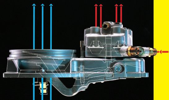
Air-shrouded fuel-injection valves a In rest position,
Air-shrouded injection valves improve the b In actuated position.
mixture formation particularly at idle. 1 Valve housing,
2 Filter,
Using the pressure drop across the 3 Valve needle,
throttle valve, a portion of the air inducted 4 Valve seat. 1
by the engine is drawn into the cylinder
through the injection valve (Fig. 20): The
result is excellent atomization of the fuel
at the point of exit (Fig. 10). Air-shrouded
injection valves reduce fuel consumption 2
and toxic emission constituents.
UMK0069-2Y
3
4
a b
Fig. 10
Spray pattern of an injection valve without
air-shrouding (left) and with air-shrouding (right).
UMK0042Y
UMK0041Y
17Gasoline- Fuel metering Principle of the air-flow sensor
injection a Small amount of air drawn in: sensor plate only
systems The task of the fuel-management system lifted slightly, b Large amount of air drawn in:
is to meter a quantity of fuel corre- sensor plate is lifted considerably further.
sponding to the intake air quantity.
Basically, fuel metering is carried out a
by the mixture control unit. This com-
prises the air-flow sensor and the fuel
distributor.
In a number of operating modes however, h
the amount of fuel required deviates
greatly from the “standard” quantity and it
becomes necessary to intervene in the b
mixture formation system (see section
“Adaptation to operating conditions”).
h
UMK0072Y
Air-flow sensor
The quantity of air drawn in by the engine
is a precise measure of its operating
Fig. 11
load. The air-flow sensor operates ac-
cording to the suspended-body principle, air-fuel mixture. Since the air drawn in by
and measures the amount of air drawn in the engine must pass through the air-flow
by the engine. sensor before it reaches the engine, this
The intake air quantity serves as the means that it has been measured and
main actuating variable for determining the control signal generated before it
the basic injection quantity. It is the actually enters the engine cylinders. The
appropriate physical quantity for deriving result is that, in addition to other
the fuel requirement, and changes in the measures described below, the correct
induction characteristics of the engine mixture adaptation takes place at all
have no effect upon the formation of the times.
Fig. 12
Updraft 1 2 3 4 5
air-flow sensor
a Sensor plate in its
zero position, a
b Sensor plate in its
operating position.
1 Air funnel,
2 Sensor plate,
3 Relief cross-section,
4 Idle-mixture
adjusting screw,
5 Pivot,
6 Lever,
7 Leaf spring. 7 6
b
UMK1654Y
18The air-flow sensor is located upstream Barrel with metering slits K-Jetronic
of the throttle valve so that it measures all 1 Intake air, 2 Control pressure, 3 Fuel inlet,
the air which enters the engine cylinders. 4 Metered quantity of fuel, 5 Control plunger,
It comprises an air funnel in which the 6 Barrel with metering slits, 7 Fuel distributor.
sensor plate (suspended body) is free to 7
pivot. The air flowing through the funnel 2
deflects the sensor plate by a given ,,,,,
,,,,,
amount out of its zero position, and this 5 ,,,,, 6
4 ,,,, ,,,, 4
,,,,,,,,,,,,,,,,
movement is transmitted by a lever sys- ,,,,
,,,, ,,,,
,,,, ,,,,
,,,, ,
,,,,
,,,
,,,,,,,,,,,,,,,,
tem to a control plunger which deter- 3
,,,,
,,,, , ,,,
,,,,
,,,,,,,,,,,,,,,,
mines the basic injection quantity re-
,,,,,,,,,,,,,,,,
quired for the basic functions. Consider-
,,,,,,,,,,,,,,,,
able pressure shocks can occur in the
,,,,,,,,,,,,,,,,
intake system if backfiring takes place in
,,,,,,,,,,,,,,,,
the intake manifold. For this reason, the 1
,,,,,,,,,,,,,,,,
air-flow sensor is so designed that the
UMK1496Y
,,,,,,,,,,,,,,,,
sensor plate can swing back in the
opposite direction in the event of misfire,
and past its zero position to open a relief Fig. 13
cross-section in the funnel. A rubber
buffer limits the downward stroke (the Fuel distributor
upwards stroke on the downdraft air-flow Depending upon the position of the plate
sensor). A counterweight compensates in the air-flow sensor, the fuel distributor
for the weight of the sensor plate and meters the basic injection quantity to the
lever system (this is carried out by an individual engine cylinders. The position
extension spring on the downdraft air- of the sensor plate is a measure of the
flow sensor). A leaf spring ensures the amount of air drawn in by the engine. The
correct zero position in the switched-off position of the plate is transmitted to the
phase. control plunger by a lever.
Fig. 14
Barrel with metering slits and control plunger
a Zero (inoperated position), b Part load, c Full load.
1 Control pressure, 2 Control plunger, 3 Metering slit in the barrel, 4 Control edge, 5 Fuel inlet,
6 Barrel with metering slits.
,,,,,, ,,,,,, ,,,,,,
a ,,,,,, b ,,,,,, c ,,,,,,
,,,,,, 1
,,,,,, ,,,,,,
,,,,,, ,,,,,, ,,,,,,
,,,,,,
,,,,,, ,,,,,,
,,,,,, ,,,,,,
,,,,,,
2
,,,,, , ,
,,,,,,, ,,,,, ,,,,, , , ,
,,,,,, ,,,,,, ,, ,,,,
3
,,,,,,,,, ,,,,,
,,,, 4 ,
, ,
, ,
, ,
,, ,,,,, , , , , ,,,,,
,,,,
,,,,, , ,,,,, , , ,
,,,,,,,,,,,,,
,,,, , , , ,
,,,, , ,
,,,,,, ,,,,,, ,
,
,,,,,
,,,,,
, ,
, ,,,, , ,
,,,, ,,,, ,,,, ,,,,
5
6
UMK1497Y
19Gasoline- Depending upon its position in the barrel Barrel with metering slits
injection with metering slits, the control plunger The slits are shown enlarged (the actual slit is
systems opens or closes the slits to a greater or about 0.2 mm wide).
lesser extent. The fuel flows through the
open section of the slits to the differential
pressure valves and then to the fuel
injection valves. If sensor-plate travel is
only small, then the control plunger is
lifted only slightly and, as a result, only a
small section of the slit is opened for the
passage of fuel. With larger plunger
travel, the plunger opens a larger section
of the slits and more fuel can flow. There
is a linear relationship between sensor-
plate travel and the slit section in the
barrel which is opened for fuel flow.
A hydraulic force generated by the so-
called control pressure is applied to the
control plunger. It opposes the movement
UMK0044Y
resulting from sensor-plate deflection.
One of its functions is to ensure that the
control plunger follows the sensor-plate
Fig. 15
movement immediately and does not, for
instance, stick in the upper end position the air drawn in by the engine can deflect
when the sensor plate moves down again. the sensor plate further. This results in
Further functions of the control pressure the control plunger opening the metering
are discussed in the sections “Warm-up slits further and the engine being allo-
enrichment” and “Full-load enrichment”. cated more fuel. On the other hand, if the
control pressure is high, the air drawn in
Control pressure by the engine cannot deflect the sensor
The control pressure is tapped from the plate so far and, as a result, the engine
primary pressure through a restriction receives less fuel. In order to fully seal off
bore (Figure 16). This restriction bore the control-pressure circuit with absolute
serves to decouple the control-pressure certainty when the engine has been
circuit and the primary-pressure circuit switched off, and at the same time to
from one another. A connection line joins maintain the pressure in the fuel circuit,
the fuel distributor and the warm-up the return line of the warm-up regulator is
regulator (control-pressure regulator). fitted with a check valve. This (push-up)
When starting the cold engine, the valve is attached to the primary-pressure
control pressure is about 0.5 bar. As the regulator and is held open during oper-
engine warms up, the warm-up regulator ation by the pressure-regulator plunger.
increases the control pressure to about When the engine is switched off and the
3.7 bar (Figure 26). plunger of the primary-pressure regulator
The control pressure acts through a returns to its zero position, the check
damping restriction on the control valve is closed by a spring (Figure 17).
plunger and thereby develops the force
which opposes the force of the air in the Differential-pressure valves
air-flow sensor. In doing so, the restric- The differential-pressure valves in the
tion dampens a possible oscillation of the fuel distributor result in a specific pres-
sensor plate which could result due to sure drop at the metering slits.
pulsating air-intake flow. The air-flow sensor has a linear charac-
The control pressure influences the fuel teristic. This means that if double the
20 distribution. If the control pressure is low, quantity of air is drawn in, the sensor-Primary pressure
and control pressure 3 ,,,,,,,,,,,,,,,,,,,,,
,,,,,,,,,,,,,,,,,,,,,
K-Jetronic
1 Control-pressure 2 ,,,,,,,,,,,,,,,,,,,,,
,,,,,,,,,,,,,,,,,,,,,
,,,,,,,,,,,,,,,,,,,,,
effect (hydraulic
,,,,,,,,,,,,,,,,,,,,,
force),
1
,,,,,,,,,,,,,,,,,,,,,
2 Damping restriction,
,,,,,,,,,,,,,,,,,,,,,
3 Line to warm-up regulator,
,,,,,,,,,,,,,,,,,,,,,
4 Decoupling restric-
,,,,,,,,,,,,,,,,,,,,,
tion bore,
,,,,,,,,,,,,,,,,,,,
,,,,,,,,,,,,,,,,,,,,,
5 Primary pressure
(delivery pressure),
6 Effect of air pressure. ,,,,,,,,,,,,,,,,,,,,,
,,,,,,,,,,,,,,,,,,,,,
,,,,,,,,, , , , , ,
,,,,,,,,,,,,,,,,,,,,,
,,,,,,,,,,,,,,,,,,,,,
,,,,,,,,,,,
,,,,,,,,,,,,,,,,,,,,,
, , , , ,
,,,,,,,,, , , , , , , , , , ,
,,,,,,,,,,,,,,,,,,,,,
,,,,,,,,,,,,,,,,,,,,,
,,,,,,,,,,,
4
UMK1498Y
6 5
Fig. 16
Fig. 17
Primary-pressure
regulator with push-
up valve in the a
control-pressure
circuit
a In zero (inoperated)
position,
b In operating position.
1 Primary pressure
intake,
2 Return (to fuel tank),
3 Plunger of the
primary-pressure
regulator,
4 Push-up valve,
5 Control-pressure b
,,,,,
,,,,,
,,,,,
intake (from warm-
up regulator). 1 5
,,,,,
,,,,,
UMK1499Y
2 3 4
plate travel is also doubled. If this travel is The differential-pressure valves main-
to result in a change of delivered fuel in tain the differential pressure between the
the same relationship, in this case double upper and lower chamber constant re-
the travel equals double the quantity, gardless of fuel throughflow. The differ-
then a constant drop in pressure must ential pressure is 0.1 bar.
be guaranteed at the metering slits The differential-pressure valves achieve
(Figure 14), regardless of the amount of a high metering accuracy and are of the
fuel flowing through them. flat-seat type. They are fitted in the fuel 21Gasoline-
,,,
Differential-pressure valve
injection
,,,
systems
a Diaphragm
,,,
position with a
low injected
fuel quantity
,,,,,,,, ,,
,,,,,,,, ,
,,,,,,,,
,,,,,,,, ,
,,,,,,,,
b Diaphragm
position with a
large injected
fuel quantity
,,,
,,,
,,,,,,,, ,
,,,,,,,, ,,
,,,,,,,, ,
,,,,,,,,
,,,,,,,,
UMK1656Y
Fig. 18
distributor and one such valve is allo- is located in the upper chamber. Each
cated to each metering slit. A diaphragm upper chamber is connected to a
separates the upper and lower chambers metering slit and its corresponding con-
of the valve (Figures 18 and 19). The nection to the fuel-injection line. The
lower chambers of all the valves are con- upper chambers are completely sealed
nected with one another by a ring main off from each other. The diaphragms are
and are subjected to the primary pres- spring-loaded and it is this helical spring
22 sure (delivery pressure). The valve seat that produces the pressure differential.Fuel distributor with differential-pressure valves K-Jetronic
1 Fuel intake
(primary 2 3 4 5 6
pressure),
2 Upper chamber of
the differential-
,,,,
pressure valve,
,,,,
3 Line to the fuel-
injection valve
(injection
pressure),
4 Control plunger,
,,,,
5 Control edge and
metering slit,
6 Valve spring, ,,,,,,,,,,
,,,,,,,,,,,,,,,,,,,,
,,,,,,,,,,
,,,,,,,,,,,,,,,,,,,,
7 Valve diaphragm,
,,,,,,,,,,,,,,,,,,,,
8 Lower chamber of
the differential-
pressure valve. 1
,,,,,,,,,,
,,,,,,,,,,,,,,,,,,,,
,,,,,,,,,,
UMK1602Y
8 7
Fig. 19
Fig. 20
If a large basic fuel quantity flows into the Mixture formation with air-shrouded fuel-
upper chamber through the metering slit, injection valve
the diaphragm is bent downwards and 1 Fuel-injection valve, 2 Air-supply line,
enlarges the valve cross-section at the 3 Intake manifold, 4 Throttle valve.
outlet leading to the injection valve until
the set differential pressure once again
prevails.
1 2 3 4
If the fuel quantity drops, the valve cross-
section is reduced owing to the equilib-
rium of forces at the diaphragm until the
differential pressure of 0.1 bar is again
present. ÀÀÀ
,,,
@@@
This causes an equilibrium of forces to ,,,
@@@
ÀÀÀ
prevail at the diaphragm which can be ,,
@@
ÀÀ
,,
@@
ÀÀ
maintained for every basic fuel quantity
,,
@@
ÀÀ
by controlling the valve cross-section. ,,
@@
ÀÀ
,,
@@
ÀÀ
,,
@@
ÀÀ
,,
@@
ÀÀ
UMK0068Y
Mixture formation
,,
@@
ÀÀ
The formation of the air-fuel mixture ,,
@@
ÀÀ
takes place in the intake ports and ,,
@@
ÀÀ
cylinders of the engine.
The continually injected fuel coming from Air-shrouded fuel-injection valves favor
the injection valves is “stored” in front of mixture formation since they atomize
the intake valves. When the intake valve the fuel very well at the outlet point
is opened, the air drawn in by the engine (Figures 10, 20).
carries the waiting “cloud” of fuel with it
into the cylinder. An ignitable air-fuel
mixture is formed during the induction
stroke due to the swirl effect. 23You can also read