Optimization of Marine Medium Speed Diesel Engine Performance based on Multi-Injector System
←
→
Page content transcription
If your browser does not render page correctly, please read the page content below

E3S Web of Conferences 236, 01026 (2021)                                                                   https://doi.org/10.1051/e3sconf/202123601026
ICERSD 2020

    Optimization of Marine Medium Speed Diesel Engine Performance
    based on Multi-Injector System
    Dai Liu1a, Yingzhu Guo1b, Long Liu1c , Qian Xia2d and Yong Gui2e
    1
        Harbin Engineering University,College of Power and Energy Engineering, Nangang district, Harbin, China
    2China    Shipbuilding Power Engineering Institute Co Ltd, Port industrial zone, Pudong new area, Shanghai, China

                   Abstract: Multi-injector system is potential to improve thermal efficiency and NOx emission of diesel engine at the
                   same time. In order to optimize the combustion and emission of Marine medium speed diesel engine, the engine
                   combustion with a multi-injector system is simulated and analyzed by CFD software Converge. In this research, two
                   injectors are installed at the side of the cylinder head while the central injector is maintained. Various injection
                   directions of side injectors and injection strategies of multi-injector system are simulated to optimize the fuel spray
                   and combustion. The analysis results show that the spray angle of the side injector plays a key role for effective
                   thermal efficiency improvement, since complex spray jet-jet interaction and spray impingement may deteriorate the
                   combustion if the arrangement of spray angle was not set properly. Once the fuel injection direction has been
                   optimized, the fuel ratio of the three injectors is optimized and improved the effective thermal efficiency with lower
                   NOx emission. The results show that the two side injectors could increase the fuel injection rate into the cylinder,
                   leading to high brake power and consequently increased the thermal efficiency by 1.26% and decreased the NOx
                   emission by 16% for the best optimization.

                                                                                 as the PREDIC [2]and MULDIC [3] concepts proposed in
                                                                                 the Premix compression ignition (PCCI) combustion
          1 Introduction                                                         control study. Researchers have confirmed that the use of
          With the exhaustion of petroleum fuel and increasingly                 multiple injectors can reduce heat loss [4, 5].
          severe environmental pollution, more stringent                             Noboru Uchida et al. [6] carried out numerical analysis
          requirements on the economy and emission of Marine                     and tests to investigate the combustion and emission
          diesel engines has been proposed. The large bore diameter              characteristics of diesel engines by adopting multi-injector
          (normally more than 250mm) and long injection duration                 and newly designed cavity single cylinder engine. Their
          (can reach 5ms for high load) of medium-speeds diesel                  results indicated that friction loss, heat loss and NOx
          engine leads to increasing of near wall combustion and                 emissions can be reduced while maintaining the indicated
          long combustion duration. Both of them would result in a               thermal efficiency by independently controlling the
          decreasing of the thermal efficiency.                                  injection timing of each injector. In addition, the improved
              To solve this problem, a novel fuel system with two or             nozzle with large flow coefficient and reduced holes is
          more injectors per cylinder is proposed. The novel multi-              used in the side injector to generate the swirl spray and
          injector system is expected to provide three advantages in             improved the braking thermal efficiency significantly.[7].
          combustion: Firstly, shorten the fuel injection duration.              Takeda Y and et al [8] installed three injectors in a
          More fuel could be injected into the cylinder to reduce the            traditional single cylinder diesel engine. One injector was
          combustion duration and improve the thermal efficiency.                installed vertically in the center of the cylinder, the other
          Secondly, the mixture is facilitated by a continuous flow              two injectors was installed on the side of the cylinder.
          of air upstream of the spray. Through numerical and                    through the experiments, they confirmed several
          experimental results, Koci et al. [1] found that the external          optimization settings for the fuel quantity and injection
          air-assisted fuels spray may reduce the local equivalence              timing of each injector. Both particle emission and fuel
          ratio by enhancing the fuel/air mixing process. Thirdly, the           consumption were improved with remained low NOx
          heat loss of the wall can be reduced since the fuel injected           levels. Gustav [9] also carried out experiments on a heavy-
          from the side injectors is concentrated in the center of the           duty engine with multi-injector system. He further
          cylinder and consequently reduced the impact of flame                  investigated the spray and combustion behavior through
          near the cylinder wall. Several studies have been                      optical engine, and
          conducted on diesel engines with multiple injectors, such              compared the flame structures of single-injector and multi-
                                                                                 injector system. Compared with the single injector system,

    a                           b
        dailiu@hrbeu.edu.cn         gyz12072020@126.com        Corresponding author: c liulong@hrbeu.edu.cn       d   xq@cspi.net.cn
    e   gyong@cspi.net.cn

  © The Authors, published by EDP Sciences. This is an open access article distributed under the terms of the Creative Commons Attribution License 4.0
  (http://creativecommons.org/licenses/by/4.0/).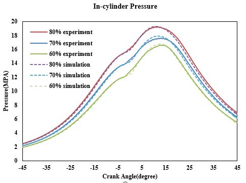
E3S Web of Conferences 236, 01026 (2021)                                                                               https://doi.org/10.1051/e3sconf/202123601026
ICERSD 2020

       the high temperature zone is located further away from the                Auto ignition                       Shell
       cylinder boundaries in the cases of three-injector system,                Spray breakup                        KH-RT
       which leads to the reduction of heat loss and improvement
       of braking thermal efficiency.                                           2.2 Model validation
           The diesel engines in the above examples are all
       vehicle engines, indicating that the novel fuel system can               In the engine model, the simulation only covers the
       reduce or maintain emissions and improve thermal                         combustion process from inlet valve closing to exhaust
       efficiency at the same time for the diesel engines of                    valve opening. In order to ensure the accuracy of the
       smaller size .The combustion chamber of marine diesel                    simulation results, the spray and combustion sub-models
       engine is much larger than that of the vehicle diesel                    were calibrated according to the experimental data and the
       engine, which is an advantage for multiple injectors                     calibration results are shown in figure 1 and 2, respectively.
       arrangement and fuel/air mixing under the condition of                   The experimental results of spray is from literature[10] and
       complex fuel jet distribution in the cylinder. Therefore,                the experimental data of engine combustion are provided
       the novel fuel system is applied in a marine diesel engine               by manufacturer. It is obvious that the simulated fuel spray
       through a validated 3D model. Two injectors with 3 nozzle                agreed with experimental data well. Then, parameters of
       holes are set on the side of the cylinder head, while the                the spray sub-model are maintained for the combustion
       original injector is maintained. The spray orientations of               calibration. The comparison of simulated cylinder
       each hole in the side injector were simulated to ensure the              pressure curve and experimental data under three loads is
       best thermal efficiency. However, the optimized nozzle                   shown in FIG. 2. The curves agree well and the model can
       structures of side injectors are not able to increase the                be used for further research.
       thermal efficiency if the injection strategy was not
       properly optimized. After further combined with proper                                                            Penetration
       injection strategy, the thermal efficiency was increased                                     200
       with NOx emission decreased finally.                                                         180             experiment
                                                                                                    160             simulation
                                                                                  Penetration(mm)

                                                                                                    140
       2 Simulation model, model validation                                                         120
       and work scheduling                                                                          100
                                                                                                     80
       2.1 Simulation model                                                                          60
                                                                                                     40
       In this study, CFD software CONVERGE was applied to                                           20
       conduct simulation modeling on a marine medium-speed                                           0
       diesel engine, and the configuration of the diesel engine                                          0              1                2             3
       was shown in Table 1. The basic mesh size is 20.0mm,                                                                  SOinj(ms)
       applying adaptive mesh refinement for velocity and
       temperature. The                                                                                   Figure 1 shows the overall data comparison
                                 Table 1 Engine specifications.
           Base Engine Configuration             Single cylinder/4 stroke
           Displacement
           Stroke                                550 mm
           Bore                                  390 mm
           Connecting Rod                        1200 mm
           Compression ratio                     17.5:1
           Fuel Injection System                 Common rail
           Center nozzle orifice                 0.63mm×12ͧ0.1257m3/minͨ
           Side nozzle orifice                   0.63mm×3(0.0314m3/min)
                                                 0.8mm×3(0.0507m3/min)
           Maximum injection pressure            1500Mpa

       subdividing criteria are differences of 1.0 m/s and 2.5 K
       in the adjoining meshes, respectively. The area where the
       fuel injector located is encrypted layer by layer along the
                                                                                Figure. 2 Comparison of cylinder pressure between simulation
       injection direction of the fuel spray. The minimum grid                                        and experiment
       size are0.625
       mm. The O 'Rourke model was used for wall heat transfer
       calculation, and the sub-models applied for simulation
       engineering were shown in Table 2.
                Table 2. Sub-models used by CONVERGE.                          2.3 Work scheduling
           Phenomenon                  Model
           Turbulence                  RNG k–
                                                                                In order to compare the combustion characteristics and
           Combustion                  Characteristic time combustion           thermal efficiency after replacing the fuel injection system,
                                       (CTC)                                    a series of simulation were carried out (Table 2). The


                                                                            2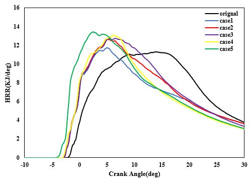
E3S Web of Conferences 236, 01026 (2021)                                                              https://doi.org/10.1051/e3sconf/202123601026
ICERSD 2020

       injector structure and arrangement in the simulation were              of the main injector, results in a longer injection duration
       shown in Figure 3. The start of injection was set at -6CAD             and consequently a longer combustion duration with
       for each injector and fuel quantity was set as 4:3:3, which            higher exhaust loss. However, it is still worthy to analyze
       means that the central injector provides 40% of fuel                   the distribution of high temperature area in the combustion
       quantity and the side injectors provide 30% for each. The              chamber, which is the main influencing factor for heat loss.
       position variations of the side injector are determined                Figure 5 reflects the effect of 1 on the temperature
       through the observation of fuel spray distribution and                 distribution in the combustion chamber (the sectional
       interaction in the combustion chamber before simulation.               plane is 20mm away from the cylinder head). All multi-
       If there are obvious increased fuel interaction and wall               injector cases show a tendency of increased combustion
       impingement, the positions and nozzle orientations at this             zone in the center of cylinder. The change of 1 means that
       condition were set as boundary position. Therefore, the                the overall injection direction changes, which affects the
       variations of nozzle orientations can be limited to a                  distribution of the fuel combustion in the cylinder. As 1
       smaller range for simulation. Considering the cylinder                 reduced, of the fuel penetration of side injector to the
       head structure and the position of the valves, the position            center of the combustion chamber is reduced due to the
       of the side injector is setting 175mm away from the center             interaction of fuel jet from the central injector, and the high
       of the cylinder head. The side injector is installed at an             temperature region of the central part showed a tendency
       inclined Angle of 25° from the axis and its nozzle                     to be expanded. In addition, the heat release rate at the later
       orientations is varied as shown in table 3 for optimization.           stage of combustion (around 20CAD ATDC) tends to
                         Table 3, Simulation cases matrix                     increase as 1
              1˄deg˅       2˄deg˅         1˄deg˅         2˄deg˅           increases (shown in figure 6), which can be explained by
                                                                              the reduced interaction of fuel jet from different injectors
               -10/0/8          20             12.5            7              shown
                 -10         19/20/23          12.5            7              in figure 5. Overall, the 1 indicated an obvious influence
                 -10            20             12.5          5/7/9
                                                                              in spray and combustion distribution, a slightly larger
                 -10            20        10.5/12.5/14.5       7
                                                                              angle can reduce the fuel jet-jet interaction and promote
                                                                              the combustion and thermal efficiency, even though there
                                                                              is a slight increase in heat loss (around 0.2%).


           Figure. 3 Schematic diagram of simulation related parameters

                                                                                        Figure. 4 Influence of 1 on energy balance
       3 Results and Discussion
                                                                               1     0eCA               10eCA             20eCA
       The spray direction and fuel quantity ratio determine the               -10
       spray distribution and interaction, which affects the
       fuel/air mixing and combustion process. Various cross
       section angle, longitudinal section angle and fuel quantity
       ratio were simulated.
                                                                               0
       3.1 Influence of cross section angle
       The effect of 1 on combustion and performance is shown
       in Figure 4, 5 and 6. Both of the heat loss and effective
       thermal efficiency are reduced when 1 reduced from 8
                                                                               8
       degree to -10degree. Although the heat loss is reduced
       obviously, the overall effective thermal efficiency of the
       multi-injector case is still lower than that of the original
       engine, which is due to the increasing of exhaust loss. The
       size of the side injector is limited by the space of cylinder
       head (valves and coolant channel). Therefore, the highest
       injection quantity of the selected side injector is only 1/4


                                                                          3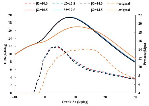
E3S Web of Conferences 236, 01026 (2021) https://doi.org/10.1051/e3sconf/202123601026
ICERSD 2020
ᵪ
An Temperature(K)
not 900 1175 1450 1725
atio 2000
n
Figure 5. Influence of 1 on temperature field distribution
Figure. 7 Influence of 2 on energy balance
2 0eCA 10eCA 20eCA
19
20
Figure 6 Influence of 1 on HR-Rate 23
The influence of injection orientation angle˄2˅ on
combustion performance is shown in figure7,8 and 9 .
Considering the wall impingement and the jet-jet
interaction of the fuel spray of side injector, the variation
range of 2 is set between 19 and 23 degree. As 2 A Temperature(K)
increases, the heat loss decreases and exhaust loss nn 900 1175 1450 1725 2000
increases. The later energy loss indicates a dominated ot
ati
influence on the effective thermal efficiency. When the 2 on
increases, the distribution of high temperature region
becomes more dispersed (shown in Figure8). This is Figure 8. Influence of 2 on temperature field distribution
because the increased interaction between fuel jets from
side injector and central injector, which is indicated by the
less penetration of fuel spray from side injector with
bigger 2 shown in figure 9. It leads to a worse fuel/air
mixture and a decrease in the heat release rate at the later
stage of combustion (shown in figure 9). In addition, the
reduction of high temperature region near cylinder wall as
2 increase might be responsible for the reduction in heat
loss. Overall, the reduction in 2 leads to reduced fuel jets
interaction and better utilization of air in the combustion
chamber and consequently increases the effective thermal
efficiency.
Figure 9 Influence of 2 on HR-Rate
3.2 Influence of longitudinal section Angle
Similarly, the influence of the longitudinal section angle
(LA) on the combustion and performance is shown in
figure 10, 11 and. From the energy balance and heat
release rate analysis in figure 10 and 11, the effect of angle
4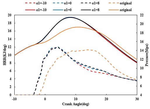
E3S Web of Conferences 236, 01026 (2021)                                                            https://doi.org/10.1051/e3sconf/202123601026
ICERSD 2020

       1 is slight, the difference is less than 0.03% for thermal         obvious reduction of thermal efficiency and heat release
       efficiency. There is no obvious difference for other                rate can be observed in figure 10and 11. This might be
       characteristics, such as heat and exhaust loss. For the other       because the larger angle of lower spray orientation
       angle 2, there is only a slightlyimprovement in heat loss         increases the impingement of cylinder head at central part
       and thermal efficiency when 2 decreases from 12.5 to               and consequently deteriorates the combustion and
       10.5 degree although its exhaust loss increased slightly.          increases the exhaust loss. Overall, the longitudinal
       As 2 further increases to 14.5 degree, an                          section angle can be confirmed as 7 and 12,5 degree for
                                                                           further optimization.

                                                                           3.3 Impact of fuel injection strategy
                                                                           As mentioned above, optimization of the injection angle
                                                                           can improve the effective thermal efficiency. However, the
                                                                           thermal efficiency is still lower than that of original engine,
                                                                           due to the smaller fuel flow the side injector, which limited
                                                                           by the space of cylinder head and specification of fuel
                                                                           injectors. If the nozzle hole diameter of side injector can
                                                                           be modified to achieve a higher flow rate, the thermal
                                                                           efficiency has the potential to be further improved [11,12]. In
                                                                           addition, the previous fuel injection quantity of the side
                                                                           injector leads to longer injection and combustion duration
                                                                           significantly compared with those of original engine,
                                                                           which is the main reason for the low thermal efficiency in
                                                                           previous cases. This
                                                                           section aims to solve the two problems by optimizing the
                                                                           fuel injection strategy and hole diameter based on the
                                                                           optimized injection orientation angle in previous section.
                                                                           The simulation cases are shown in Table 4.
                                                                               Figure 12, 13, and 14 compare the effects of injection
             Figure.10 Influence of 1 and 2 on energy balance            strategies on combustion characteristics and energy
                                                                           balance. It can be seen that increasing the fuel injection
                                                                           quantity ratio of the main injector (case 1, 2 and 3) is
                                                                           beneficial to increase the effective thermal efficiency. This
                                                                           is due to the fact that the overall injection duration is
                                                                           reduced as the fuel ratio reduced from 4:3:3 to 4:1:1 with
                                                                           the same fuel injection quantity. Thus, the combustion is
                                                                           improved dramatically (shown in figure 13) and
                                                                           consequently increases the heat loss slightly and decre ases
                                                                           the exhaust loss obviously. It should be noted that the heat
                                                                           loss of case3 is slightly lower than that of case2, and the
                                                                           increase of effective thermal efficiency is not large.
                                                                           Comparing the temperature distribution of case 1, 2 and 3
                                                                           in figure 14, it is obvious that the high-temperature zone
                                                                           in the combustion chamber tends to be more uniformly
                                                                           distributed, which means that the fuel/air mixture is
                                                                           improved and it is also confirmed by the results of heat
                                                                           releases rate at later combustion period in figure 13. As can
                                                                           be seen from figure 13, the heat release rate of case3 after
                                                                           25ATDC is lower than case2. This change means that the
                                                                           temperature in the Figure 13. Influence of fuel injection
                                                                           strategy on HR-Rate and in-cylinder pressure combustion
                                                                           chamber of case3 later is lower than

                  Figure 11 Influence of LA on HR-Rate


                                                                       5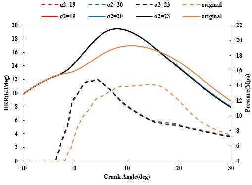
E3S Web of Conferences 236, 01026 (2021)                                                                https://doi.org/10.1051/e3sconf/202123601026
ICERSD 2020

                                                        Table 4, Simulation cases matrix
            case                          Main spray start Start of side spray
                    Distribution ratio                                            Main     injector        Side       injector   Dimensions of
                                          time˄CA˅          ˄CA˅
                    of        injection                                           duration                 duration              side   injector
                    volume                                                        ˄deg˅                    ˄deg˅                 orifice˄mm˅
            1       4:3:3                 -5                    -5                    11.265               25.948                0.63
            2       2:1:1                 -5                    -5                    12.917               21.655                0.63
            3       4:1:1                 -5                    -5                    15.761               15.728                0.63
            4       2:1:1                 -5                    -5                    12.917               14.181                0.8
            5       2:1:1                 -7                    -5                    12.917               14.181                0.8
            Select 1 = 8 °, 2 = 20 °, 1 = 7 °and 2 = 12.5 ° this combination as a foundation for the subsequent optimization
            work.

                                                                                 1

                                                                                 2

       Figure 12 Influence of fuel injection strategy on energy balance
                                                                                 3

                                                                                 4

                                                                                 5

                                                                                 Anno                      Temperature(K)
                                                                                 tation      900    1175    1450    1725    2000


                                                                                     Figure 14. Influence of strategy on temperature field
                                                                                                         distribution
                                                                                temperature is increased as the heat release increased, the
                                                                                brake specific NOx emissions of case 1, 2 and 3 are still
                                                                                less than that of original engine, because brake power
           Figure 13. Influence of fuel injection strategy on HR-               output is improved as fuel quantity ratio increased. It is
                       Rate and in-cylinder pressure                            also the reason to explain the significant reduction of the
       case2. This trend explains that the heat loss of case3 is slightly       exhaust loss while the in-cylinder pressure and
       lower than case2. As can be seen from Figure 15, although the            temperature is increased. By maintaining the fuel quantity
       combustion                                                               ratio as 2:1:1 and injection timing with increasing the
         Case         0eCA               10eCA              20eCA               nozzle hole diameter of side injector, further simulation is
                                                                                conducted in case 4 and compares with case 2. Although
                                                                                the fuel flow of side injector is increased, the in-cylinder
                                                                                combustion was not improved due to the impact of worse
                                                                                the fuel breakup and atomization for the injector of larger


                                                                            6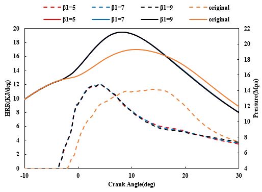
E3S Web of Conferences 236, 01026 (2021)                                                            https://doi.org/10.1051/e3sconf/202123601026
ICERSD 2020

       nozzle hole. An obvious drop can be observed at diffusion                  three injectors, shorten the injection duration, can
       combustion period in the heat release rate for case 4.                     significantly improve the thermal efficiency
       Comparing the temperature distribution of case 4 to that                   effectively. When the total injection time of the three
       of case 2, the combustion of side injection fuel is not                    injectors is the shortest, the thermal efficiency can be
       obviously observed at 10 CAD ATDC. The incomplete                          improved by 1.26
       combustion at case 4 leads to increasing of exhaust loss                   % and the NOx can be reduced by 16%.
       dramatically and the reduction of in-cylinder the heat loss           z    Increasing the nozzle hole diameter of the side
       due to the lower combustion temperature. However, the                      injector does not shorten the overall duration of
       benefit of heat loss still can’t compensate the exhaust lo ss              combustion, but decreases the effective thermal
       and results in a low thermal efficiency. By further                        efficiency due to the deteriorate fuel atomization and
       advancing the injection time of the main injector from -                   evaporation.
       5CAD to -7CAD, the effective thermal efficiency is which              z    Advanced injection timing of central injector
       is indicated by the heat release rate in figure 13. However,
       the combustion of fuel injection of side injector is still not             increases the thermal efficiency obviously, but can’t
       obvious observed based on the temperature distribution in                  improve other characteristics, such as NOx emission,
       figure 14, which leads to an increased in case 5. This is                  heat loss, exhaust loss, peak in-cylinder pressure and
       due to the advance of the injection angle leads to an earlier
                                                                                  maximum pressure rise rate. Other strategies should
       start and end of combustion, unchanged heat release rate
       in the later stage of combustion shown in figure 13.                       be combined to avoid those side effects of using
       However, the advanced injection timing also increased the                  advanced injection timing.
       heat loss, mechanical loss and NOx emission, because it               z    Compared with the single injector, the distribution of
       increased the combustion peak pressure, which reduces
       the effect of thermal efficiency improvement. Overall,                     temperature field in the combustion chamber is more
       decreasing the injection duration might be the main factor                 uniform when using multiple injectors, and the high
       to improve thermal efficiency and NOx emission at the                      temperature area in the center of the combustion
       same time.
                                                                                  chamber increases, effectively increases the air
                                                                                  utilization rate and reduces heat release.

                                                                             Acknowledgments
                                                                             The authors gratefully acknowledge the support of
                                                                             Research of Controllable Combustion Technology in
                                                                             Marine Diesel Engine (granted No. 2017YFE0116400)
                                                                             from National Key R&D Program of China, Ministry of
                                                                             Science and Technology.

           Figure 15. influence of strategy on emission characteristic       Reference
                                                                             1.  Koci, C., Florea, R., Das, S., Walls, M., Simescu, S.,
       4 Conclusion                                                              Roberts, C. (2013) Air-assisted direct injection diesel
                                                                                 investigations. SAE technical paper 2013-01-0907.
       In order to investigate the influence of fuel injection
       direction and strategy on engine thermal efficiency and               2. Nakagome, K., Shimazaki, N., Niimura, K.,
       emission, the multi-injector system is developed in a CFD                 Kobayashi, S.(1997) Combustion and emission
       large bore marine medium speed engine. Comparing the                      characteristics of premixed lean diesel combustion
       results of multi-injector system to those of the original                 engine. SAE technical paper 970898.
       engine, the main conclusions are as follows:                          3. Hashizume, T., Miyamoto, T., Hisashi, A., Tsujimura,
       z Heat loss is always reduced by applying the multi-                      K., (1998) Combustion and emission characteristics
             injector system because part of fuel is combusted at                of premixed lean diesel combustion engine. SAE
             the center of combustion chamber and consequently                   technical paper 980505.
             reduced near wall combustion.                                   4. Nyrenstedt,G., Al Turkestani,T., Im, H., Johansson,
       z Compared with the injection direction of longitude,                     B.,
             the influence of the section injection direction on the
                                                                             (2019)"CFD Study of Heat Transfer Reduction Using
             energy balance is more obvious. The appropriate
                                                                                 Multiple Injectors in a DCEE concept". SAE technical
             selection of section Angle can improve the thermal
                                                                                 Paper 2019-01-0070.
             efficiency. It should be noted that 2 needs to be
             carefully designed to avoid oil and gas hitting the             5. Nyrenstedt, G., Im,H . , Andersson, A., Johansson, B.,
             cylinder head. Otherwise, the thermal efficiency                    (2019) "Novel Geometry Reaching High Efficiency
             would be reduced obviously.                                         for Multiple Injector Concepts," SAE technical Paper
       z By adjusting the ratio of the amount of oil between                     2019-01-0246.


                                                                         7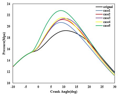
E3S Web of Conferences 236, 01026 (2021)                                                 https://doi.org/10.1051/e3sconf/202123601026
ICERSD 2020

       6.   Noboru, U., Takeshi, O., Hiroki, W., (2018) A new           Review,2016,https://www.energy.gov/sites/prod/files
            concept of actively controlled rate of diesel               /2016/06/f32/ace098_kocher_2016_o_web.pdf.
            combustion for improving brake thermal efficiency of
            diesel engines: Part ĉ—verification of the concept.
            International J of Engine Research Vol. 19(4) 474–
            487.
       7.   Noboru, U., Hiroki, W., (2019) A new concept of
            actively controlled rate of diesel combustion
            (ACCORDIC): Part II—simultaneous improvements
            in brake thermal efficiency and heat loss with
            modified nozzles. International J of Engine Research,
            Vol. 20(1) 34–45
       8.   Takeda, Y., Niimura, K., Bingquan, Z., (1998)
            Combus-tion and emission characteristics of diesel
            engines using multiple injector systems. Foreign
            internal combustion engine ,4(2)˖19-28.
       9.  Nyrenstedt, G., Watanabe, K., Enya, K., Shi, H.,
           Uchida, N., Johansson, B., (2019) Thermal Efficiency
           Compar-ison of Different Injector Constellations in a
           CI Engine. SAE International Technical Paper.2019-
           24-0172,
       10. Beat, R., Kai, H., Konstantinos, B., (2015)
           Experimental investigation on the characteristics of
           sprays represent-tative for large 2-stroke marine
           diesel engine combustion systems. SAE International
           Paper,2015-01-1825.
       11. Graf, G., Seitz, H., Theissl, H., Machold, A., (2017)
           Further ther mal efficiency increase of the diesel
           combustion for com mercial engines.               In:
           Proceedings of 4th ATZ international engine
           congress, Baden.212-223.
       12. Kocher,L.,(2016) Cummins 55% BTE project,
           presentation material in 2016 US DOE Annual Merit


                                                                    8
You can also read