Numerical investigation on combustion and NOx emissions of a CH4 / kerosene afterburner
←
→
Page content transcription
If your browser does not render page correctly, please read the page content below
E3S Web of Conferences 286, 01002 (2021) https://doi.org/10.1051/e3sconf/202128601002
TE-RE-RD 2021

 Numerical investigation on combustion and NOx
 emissions of a CH4 / kerosene afterburner
 Andreea Cristina Mangra1,* and Ene Barbu1
 1
 Romanian Research & Development Institute for Gas Turbine COMOTI Bucharest, Romania

 Abstract. Cogeneration groups equipped with gas turbines usually
 operate with natural gas. The new requirements regarding the flexibility of
 functioning both with conventional and alternative fuels have led to the
 development of new solutions. An afterburning installation facilities, on
 the one hand, the combustion of fuels which can not normally be used in
 gas turbines, and on the other hand, allows a rapid adaptation of the
 cogeneration group to the user's variable thermal energy requirements. In
 some cases, an afterburning installation may contribute to the reduction of
 NOx emissions. It also increases the group's adaptability to changing
 environmental conditions, especially during the summer. Having in mind
 these tendencies and starting from the data collected from the 2xST 18 –
 Suplacu de Barcau cogeneration plant, this paper presents a numerical
 analysis of an afterburner in order to switch from natural gas to natural gas
 / kerosene functioning, with minimal modifications to the existing solution.
 A 3D steady RANS numerical integration of the Navier-Stokes equations
 has been carried out using the commercial software ANSYS CFX. For
 future research work, it will be taken into consideration the use of more
 complex reaction mechanisms and the variation of the spray angle will be
 considered. Also, in order to validate the CFD results a combustion
 experiments campaign will be conducted.

 1 Introduction
 Cogeneration groups equipped with modern gas turbines have to meet the requirements
 regarding the flexibility of functioning both with conventional and alternative fuels. Also,
 the pollutant emissions, have to be kept at a low level, even in partial load operation
 conditions.
 The high oxygen content in the exhaust gases coming from the gas turbine, around 11-
 16 % vol. [1], can be used in the combustion of an additional amount of fuel (afterburning).
 Afterburning is generally used on supersonic military aircrafts at take-off or during
 combat [2].
 The utilization of an afterburning installation on cogeneration groups equipped with gas
 turbines increases the flexibility regarding of the used fuel and allows a rapid adaptation to
 the user's variable thermal agent requirements [3].

 *
 Corresponding author: andreea.petcu@comoti.ro

© The Authors, published by EDP Sciences. This is an open access article distributed under the terms of the Creative Commons
Attribution License 4.0 (http://creativecommons.org/licenses/by/4.0/).
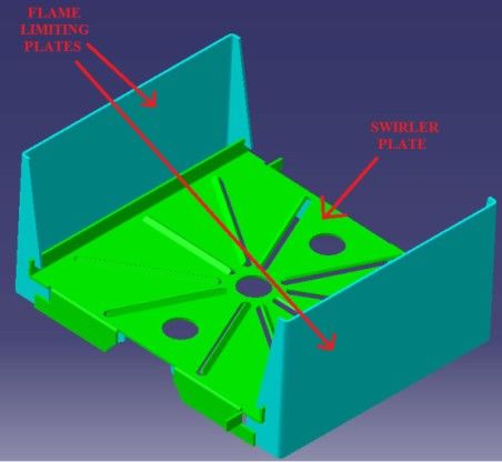
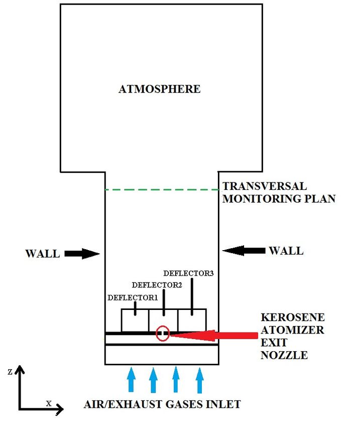
E3S Web of Conferences 286, 01002 (2021) https://doi.org/10.1051/e3sconf/202128601002
TE-RE-RD 2021

 The control of the combustion process and of the afferent pollutants emissions, while
 complying with increasingly restrictive legislative requirements, remains one of the main
 challenges of designing a combustion system. In the field of cogeneration groups with gas
 turbines, combustion process modelling inside the afterburner becomes an integral part of
 the entire group design.
 In the scientific literature, afterburning numerical modelling addresses, besides pollutant
 emissions reduction issues, aspects related to efficiency gains, compensation of
 environmental parameters variations, impact on the recovery boiler, optimization of flow
 conditions etc.
 Sullivan-Lewis [4] analyzes several afterburner geometrical configurations regarding
 the functioning with low NOx and CO emissions, at a given fuel/air ratio and the geometry's
 influence on the combustion stability. Ganjehkaviri [5] has conducted a study on the impact
 of introducing an afterburner into a combined cycle power plant. Elmegaard et al. [6]
 studied the possibility of using a polycarbonate afterburning installation - functioning on
 natural gas / biogas or pyrolysis gas - to increase the efficiency of a power plant with
 indirect combustion gas turbine. Mehrabani et al. [7] proposed using an afterburning
 installation to compensate for the environmental parameters variation and to increase the
 efficiency of combined cycle power groups. Backlund [8] shows that parallel flow burners
 lead to: larger steam flows, a high efficiency of the gas turbine power plant, an efficient use
 of the oxygen from the exhaust gases coming from the gas turbine, a larger range of
 operating regimes, low NOx and CO emissions. Ahamed [9] analyzes various methods to
 improve the blending of fuel with exhaust gases from a turbo-engine, as well as the impact
 on the recovery boiler. Shi [10] optimizes the velocity and temperature fields upstream and
 downstream of the afterburner using numerical modelling. To determine the performance of
 an afterburner, Lezsovits et al. [11] used the commercial software ANSYS CFX 5.6.
 The construction of the 2xST 18 - Suplacu de Barcau cogeneration plant, which has an
 afterburner installation functioning on natural gas with multiple parallel flows, led to
 researches regarding performance improvement. The afterburner was designed to function
 using as oxidant exhaust gases from a turbo-engine. However, in emergency cases (when
 there is a problem with the turbo-engine), it can also function with pure air as oxidant, air
 delivered by a fan.
 Similar to the afterburner in the 2xST 18 cogeneration plant, a test bench for a 3-
 modules afterburner with a single gas supply ramp has been built in INCDT COMOTI [12]
 (Figure 1 a)).
 Each afterburner module is composed of a deflector and 3 fuel nozzles. The central fuel
 nozzle, with a diameter of 6 mm, is the primary one. The other two are secondary ones with
 a role in flame propagation from one module to another. The deflector is fixed to the fuel
 ramp by the means of the 2 secondary fuel nozzles. The deflector (Figure 1 b)) is composed
 of a horizontal swirler plate and two vertical plates with the role of limiting the flame.
 This configuration of the afterburner module insures a good mixing of the fuel (natural
 gas) with the oxidizer (exhaust gases from the turbo-engine / pure air). It insures the
 cooling of the area surrounding the afterburner, the stabilization of the flame front and leads
 to obtaining higher temperatures downstream, with low pollutants levels.

 2
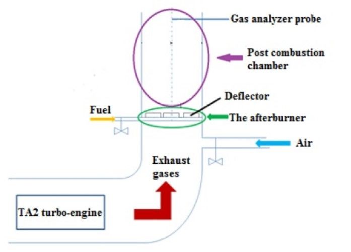
E3S Web of Conferences 286, 01002 (2021) https://doi.org/10.1051/e3sconf/202128601002
TE-RE-RD 2021

 a) b)
 Fig. 1: a) The 3-modules afterburner in COMOTI; b) the deflector

 The test bench has the possibility of testing the afterburner using as oxidant either
 exhaust gases coming from a turbo-engine or pure air (Figure 2).
 The test bench is mainly composed of: a TA2 turbo-engine running on natural gas (this
 is a TV2-117A turbo-engine converted by researchers from COMOTI to function with
 natural gas instead of kerosene), positioned horizontally, the afterburner and afterburning
 chamber positioned vertically in the turbo-engines exhaust chimney. The exhaust gases
 temperature and composition are monitored at a height of 1895 mm from the afterburner.

 Fig. 2 Median longitudinal plan section through the afterburner test bench in COMOTI

 In the context of the shown tendencies, the article presents a numerical analysis
 regarding changing the afterburner functioning on natural gas to functioning on natural gas/
 kerosene, with minimal modifications to the existing solution.

 3
E3S Web of Conferences 286, 01002 (2021) https://doi.org/10.1051/e3sconf/202128601002
TE-RE-RD 2021

 2 Numerical simulations

 2.1 Geometry
 The proposed solution consists of modifying the central module of the afterburner
 presented in Figure
 igure 1 in order to function on kerosene, the adjacent natural gas modules
 remaining unchanged.
 plications of the proposed solution, there have been
 To better understand the implications
 conducted first numerical simulations with natural gas as fuel and exhaust gases/ pure air as
 oxidant, for the configuration presented in F
 Figures 1-3.

 Fig. 3 Afterburner modules configuration

 Based on the results obtained from the numerical simulations on natural gas, there have
 been proposed an afterburner configuration functioning on kerosene. The central natural
 gas nozzle corresponding to the central module has been replaced with a liquid fuel
 atomizer.
 omizer. The atomizer exit nozzle diameter is of 0.85 mm. The other natural gas nozzles
 are blocked.

 putational domain and mesh
 2.2 Computational
 In Figure 4 a)-b)
 b) is presented the computational domain. For this domain an unstructured
 computational grid of 7.678.803 tetrahedral elements and 1.341.681 nodes has been created
 using ICEM CFD.

 a) b)
 Fig. 4 Computational domain,, on the median longitudinal plan of the afterburner: a) afterburner
 functioning on methane gas; b) afterburner functioning on kerosene

 4
E3S Web of Conferences 286, 01002 (2021) https://doi.org/10.1051/e3sconf/202128601002
TE-RE-RD 2021

 2.3 CFD settings

 A three-dimensional steady RANS numerical integration of the Navier-Stokes equations
 has been carried out using the commercial software ANSYS CFX.
 In the numerical simulations it has been considered that the natural gas is composed
 only of methane gas (CH4).
 The methane gas mass flow corresponding to one module has been chosen in
 accordance with the design parameters of the afterburner from the 2xST 18 cogeneration
 plant, functioning on natural gas [12]. It has been considered that the total fuel mass flow is
 equally distributed to each module.
 The composition of the exhaust gases, coming from the TA2 turbo-engine, used as
 oxidant is presented in Table 1.

 Table 1. Exhaust gas composition
 Mass fraction
 CO2 0.0465
 H2O 0.0418
 O2 0.1623
 N2 0.7494

 The kerosene mass flow, for the afterburner functioning with exhaust gases coming
 from the turbo-engine, was calculated according to relation (1) [13]:
 �������_���
 ̇�������� = ̇�������_��� ∙
 �������� (1)

 where: ̇�������� - kerosene mass flow (kg/s), ̇�������_��� - methane gas mass flow
 (kg/s), qmethane_gas - natural gas lower heat value [14], qkerosene - kerosene gas lower heat value
 [15].
 The kerosene mass flow, when the afterburner functions on fresh air (emergency
 regime), was calculated taking into account the maximum allowed thermal power for an
 afterburner module (350 kW) and the lower calorific value of kerosene [15].
 In practice, the measurement of the flue gas temperature is performed in the centre of
 the afterburner chamber, on the monitoring plane positioned at 1895 mm above the burner,
 using the gas analyzer's integrated temperature probe. The flue gas reference temperature,
 resulting from the cogeneration plant design data, is 1043 K [12]. Preliminary experiments
 on natural gas, performed in COMOTI (Fig. 5) [16], showed a strongly turbulent flame.
 Thus in the numerical simulations the average temperature of the flue gases on the
 monitoring plane was compared with the reference temperature of 1043 K.
 The fuel mass flow being thus set, the oxidant mass flow has been determined by
 varying it until an average temperature on the monitoring plan of 1043K, with an error of ±
 1%, has been obtained.

 5
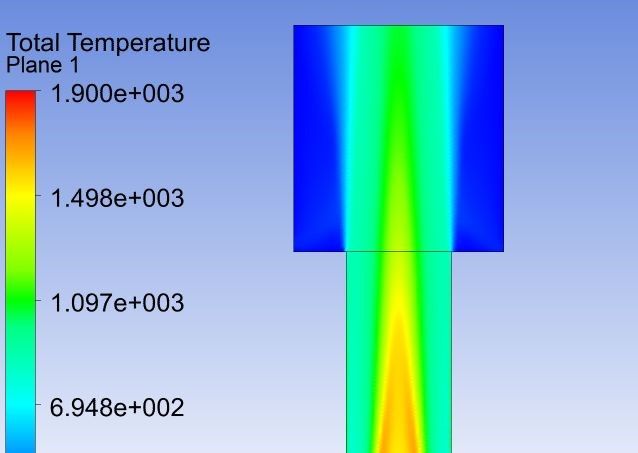
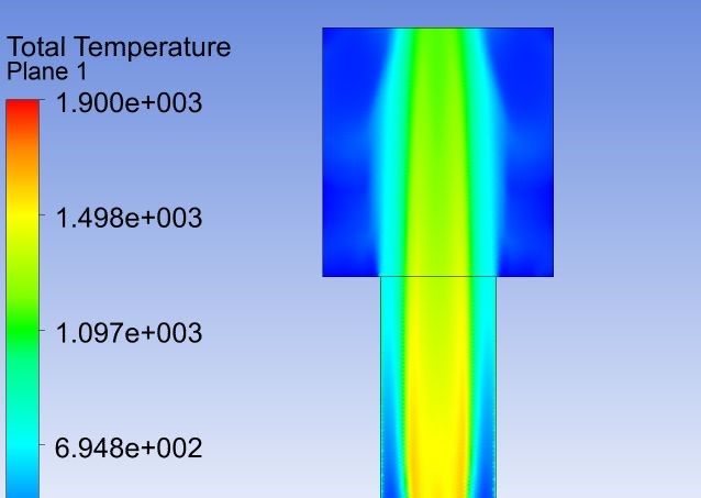
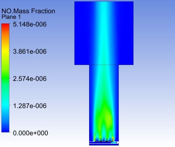
E3S Web of Conferences 286, 01002 (2021) https://doi.org/10.1051/e3sconf/202128601002
TE-RE-RD 2021

 Fig. 5 Flame structure during the preliminary experiments on the 3 modules afterburner functioning
 on natural gas

 In Table 2 are presented the boundary conditions for the considered cases.

 Table 2. Boundary conditions
 Fuel Fuel mass flow Fuel temp. Oxidant Oxidant mass Oxidant temp.
 [kg/s] [K] flow [kg/s] [K]
 CH4 0.006 293 Exhaust gases 0.813 797
 CH4 0.014 293 Air 0.65 293
 Kerosene 0.007 293 Exhaust gases 0.9 797
 Kerosene 0.008 293 Air 0.23 293

 The outlet has been considered of opening type, setting the pressure to be the
 atmospheric one.
 In these numerical simulations an Eddy Dissipation combustion Model (EDM) and a k-ε
 turbulence model have been used. The combustion model was based on a two steps
 methane-air reaction mechanism, respectively a two steps kerosene-air reaction mechanism,
 both imported from the ANSYS library [17]. Also, both used reaction mechanisms take into
 consideration the formation of thermal NO and prompt NO.
 In the case of functioning with kerosene, the fuel was uniformly injected into the
 atmosphere through the atomizer exit nozzle, under a total spray cone angle of 45°. The
 initial fuel droplets diameter was set at 0.1 mm. The break-up of the fuel droplets into
 smaller droplets was simulated using the CAB second break-up model from the ANSYS
 library. To simulate the transformation of the Jet A (kerosene) droplets into Jet A vapours a
 Liquid Evaporation Model from the ANSYS library was used.

 3 Results and discussions
 In Fig. 6 a)-b) and 7 a)-b) are presented the temperature field, respectively the NO mass
 fraction field on the afterburning chamber’s median longitudinal plan.

 6
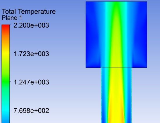
E3S Web of Conferences 286, 01002 (2021) https://doi.org/10.1051/e3sconf/202128601002
TE-RE-RD 2021

 a) CH4 - air b) CH4 - exhaust gases

 c) kerosene - air d) kerosene - exhaust gases
 Fig. 6 The temperature field on the median longitudinal plan

 a) CH4 - air b) CH4 – exhaust gases

 7
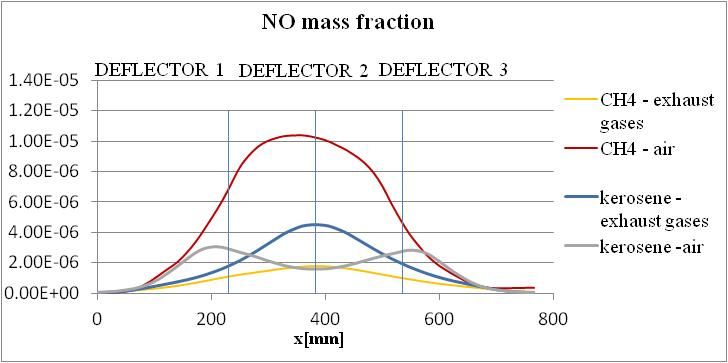
E3S Web of Conferences 286, 01002 (2021) https://doi.org/10.1051/e3sconf/202128601002
TE-RE-RD 2021

 c) kerosene -air d) kerosene - exhaust gases
 Fig. 7 The NO mass fraction field on the median longitudinal plan

 The trend followed by the NO mass fraction in the exhaust gases is consistent with the
 behaviour of the exhaust gases temperature. The NO concentration increasing with the rise
 of the temperature. The NO concentration is higher when fresh air is used as oxidant, both
 when CH4 was used as fuel, as well as when kerosene was used as fuel. The high exhaust
 gases temperature favours the dissociation of the nitrogen molecules, which leads to the
 formation of nitrogen oxides [18].
 In Fig. 8 and 9 are presented the temperature and NO mass fraction variations, along the
 central axis of the afterburner combustion chamber.

 Fig. 8 Temperature variation along the symmetry longitudinal axis

 Fig. 9 NO mass fraction variation along the symmetry longitudinal axis

 8
E3S Web of Conferences 286, 01002 (2021) https://doi.org/10.1051/e3sconf/202128601002
TE-RE-RD 2021

 As was expected the NO mass fraction increases with the temperature rise. The NOx
 emissions are significantly higher in the functioning regime CH4 - air compared with the
 functioning regime CH4 - exhaust gases. This confirms that the afterburner has been
 optimized to function in CH4 - exhaust gases regime.
 In Fig. 10 and 11 present the temperature variation on the transversal axis on the
 monitoring plan (positioned at 1895 mm from the afterburner).

 Fig. 10 Temperature variation along the transversal axis, on the monitoring plan

 Fig. 11 NO mass fraction variation along the transversal axis, on the monitoring plan

 Fig. 10 and 11 reconfirm the normal dependence between the NO emissions and the
 gases temperature. The lowest NO emissions are obtained for the functioning regime CH 4-
 exhaust gases. This is consistent with the fact that the afterburner was designed to function
 optimally in this regime. The highest NOx emissions are obtained when operating on CH4 -
 air, as emergency regime. This is observed also in the results presented in Fig. 9.
 Regarding the functioning on kerosene, further numerical investigations are necessary
 in order to optimize the afterburner. Interestingly, NOx emissions values, when functioning
 on kerosene - air, are comparable to the values obtained for functioning on CH4-exhaust
 gases from the turbo-engine.
 In Table 3 are presented the averaged temperature values obtained through numerical
 simulations, on the monitoring plan where the gas analyser probe is positioned (see Fig. 2).

 9
E3S Web of Conferences 286, 01002 (2021) https://doi.org/10.1051/e3sconf/202128601002
TE-RE-RD 2021

 Table 3. Averaged temperature on the monitoring plan
 Fuel mass flow Oxidant mass flow Temp. Temp. error
 Fuel Oxidant
 [kg/s] [kg/s] [K] [%]
 CH4 0.006 Exhaust gases 0.813 1042 0.095
 CH4 0.014 Air 0.65 1033 0.958
 kerosene 0.007 Exhaust gases 0.9 1039 0.383
 kerosene 0.008 Air 0.23 1034 0.862

 From the results in Table 3, it can be seen that, for the considered numerical simulation
 conditions, an error under 1 % for the average temperature on the monitoring plan has been
 obtained.

 4 Conclusions
 In order to study the possibility of switching the afterburner from functioning on gaseous
 fuel to liquid fuel (kerosene) functioning, a CFD analysis has been carried out. During all
 numerical simulations, it has been intended that the average temperature on the monitoring
 plan to be 1043 K ± 1%.
 The numerical modelling, confirmed that the constructive afterburner solution has been
 optimized for functioning on gaseous fuel with exhaust gases from the turbo-engine, the
 lowest NOx emissions been obtained for this functioning regime.
 Theoretical data and preliminary experiments have highlighted the turbulent structure of
 the flame, imprinted by the afterburner's modules' swirls, and the flame stability in the
 range of the analyzed CH4 mass flow (0.006 - 0.014 kg/s). In the case of functioning on
 kerosene, the flame stability and the low NOx emissions will have to be confirmed through
 experiments. The transition to kerosene functioning will be based on an original technical
 solution, which will be the subject of a patent application.
 For future research work it will be taken into consideration the possibility of the
 afterburner functioning simultaneous with CH4 and kerosene. Also, the use of more
 complex reaction mechanisms and the variation of the spray angle will be considered. In
 order to validate the CFD results, in parallel with the numerical simulations the combustion
 experiments campaign will be continued.

 References
 [1] Baukal E. Ch. Baukal, The John Zink combustion handbook (CRC Press, 2001)
 [2] R. Anand, International Journal of Advanced Research in Engineering & Management
 (IJAREM), vol. 3, issue 5, pp. 20-37 (2017)
 [3] E. I. Caceres, M. R. Montanes, O. L. Nord, Journal of Power Technologies, vol. 98,
 issue 9, pp. 188–197 (2018)
 [4] E. Sullivan-Lewis , R. Hack, V. McDonell, Assessment of a rich-burn, quick-mix, lean-
 burn–based supplemental burner system in a vitiated air stream, Combustion Science and
 Technology, ISSN: 0010-2202 (2015)
 [5] A. Ganjehkaviri, M. Yusof, M. N. M. Jaafar, Jurnal Teknologi (Sciences &
 Engineering), vol. 79, pp. 27-32 (2017)
 [6] B. Elmegaard, U. Henriksen, B. Qvale, Int. J. Thermodynamics, vol.6, No.2, pp. 85-92
 (2003)
 [7] M. K. Mehrabani et al. Thermal Science, vol. 21, No. 6B, pp. 3011-3023 (2017)
 [8] C. J. Backlund, Fiorenza E. Fiorenza, Gas Turbine and Aeroengine Congress,
 Amsterdam, The Netherlands, June 6-9 (1988)

 10
E3S Web of Conferences 286, 01002 (2021) https://doi.org/10.1051/e3sconf/202128601002
TE-RE-RD 2021

 [9] T. M. Ahamed, S. A. Nathan, International Journal of Multidisciplinary Research and
 Modern Education (IJMRME), vol. II, issue I, pp. 632-639 (2016)
 [10] X. Shi, W. Chriswindarto, D. Boyce, Proceedings of ASME 2009 Power Conference
 ASME Power 2009, July 21-23, Albuquerque, New Mexico, USA, pp. 1-8 (2009)
 [11] F. Lezsovits, S. Könczöl, K. Sztankó, Thermal Science, vol. 14, No. 3, pp. 845-854
 (2010)
 [12] E. Barbu, et al., WSEAS Transactions on Environment and Development, vol. 6, issue
 6, pp. 405-416 (2010)
 [13] I. Staffell, The energy and fuel data sheet, University of Birmingham, UK (2011)
 [14] V. Rathod, P. V. Bhale, 4th International Conference on Advances in Energy Research
 2013, ICAER 2013
 [15] T. Giampaolo, Gas Turbine Handbook: Principles and Practice (CTC Press)
 [16] E. Barbu et al., The influence of inlet air cooling and afterburning on gas turbine
 cogeneration groups performance, Gas Turbines - Materials, Modelling and Performance,
 Dr. Gurrappa Injeti (Ed.), InTech (2015)
 [17] ***.2016. ANSYS CFX-Solver Modelling Guide, release 17, ANSYS INC
 [18] H. A. Lefebvre, R. D. Ballal, Gas Turbine Combustion. Alternative Fuels and
 Emissions, 3rd edition, (CRC Press, 2010)

 11
You can also read