Laboratory Exhaust Systems Vektor-H - High Plume - July - Greenheck
←
→
Page content transcription
If your browser does not render page correctly, please read the page content below
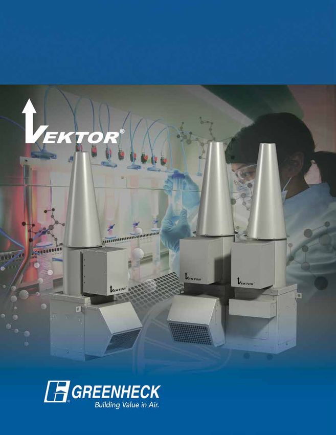
Laboratory Exhaust Systems
Vektor ®-H
High Plume

                              July
                             2020
Laboratory Exhaust Systems

The Vektor®-H is a cost-effective, self-contained, high plume laboratory exhaust system
designed to remove hazardous or noxious fumes from a laboratory, dilute the fumes with
bypass air and expel them from the laboratory building so the fumes do not contaminate
the roof area or are re-entrained into building make-up air systems.

Benefits of the Vektor-H:
• Licensed to bear the AMCA Seal for Sound and Air performance
• Applicable to constant or variable volume exhaust systems
• Meets ANSI Z9.5, NFPA 45 and ASHRAE guidelines
• Performance capacities from 500 - 26,000 cfm and up to 4 in. wg per fan
  (800 – 44,200 m3/hr and up to 1,000 Pa)
• Configurable in single, double or triple fan systems
• Spark B resistant construction

                         Greenheck Fan Corporation certifies that the Vektor-H
                         laboratory exhaust fans shown herein are licensed to
                         bear the AMCA Seal. The ratings shown are based on
                         tests and procedures performed in accordance with
                         AMCA Publication 211 and AMCA Publication 311 and
                         comply with the requirements of the AMCA Certified
                         Ratings Program. The Ratings Seal applies to sound
                         and air performance as shown in the Vektor-H
                         Performance catalog, 00.LAB.NB002 R3 4-2017

                                                                                                          Vektor-H

The Greenheck Vektor Advantage
The Greenheck Vektor-H laboratory exhaust system
is a better, lower-cost alternative to a field built-up
exhaust system.
• Installed quickly and easily on Greenheck’s
  reinforced roof curb model GPFHL
• Requires less roof deck space
• Designed to withstand up to 125 mph wind-loads
  without guy wires
• A cleaner installation with fewer roof penetrations
• No performance losses due to field fabricated
  inlet or outlet ducts
                                                                         Vektor-H system         Field built-up system

Ease of Maintenance                                                 Computer Aided Product Selection
The Vektor-H provides                                               Greenheck’s eCAPS® and CAPS® programs
safe, easy inspection and                                           provide fast selection of Vektor-H units along
maintenance of internal fan                                         with detailed drawings and fan specifications.
components. By removing one                                         Available at www.greenheck.com.
access panel, service to the
fan wheel, shaft and bearing
assembly is accomplished
without removing the fan from
the system.

2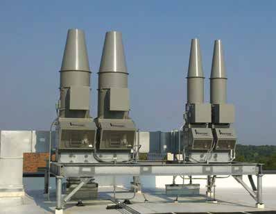
Design Features & Applications

                                                                           Applications
                            Total                                      •   High School and College Laboratories
                             Air
                                                                       •   Restaurant Exhaust
                                                                       •   Wastewater Treatment Facilities
                                                                       •   Forensic Labs
                                                                       •   Hospital Isolation Rooms
          Nozzle

                                Isolation
                                Damper

     Bypass
       Air                          Bypass
     Damper                           Air
                                    Plenum

        Bypass
          Air        Exhaust
                       Air

Performance Ranges                                          Design Versatility
Vektor-H models use an efficient tapered outlet             The Greenheck Vektor-H laboratory
nozzle to accelerate the exhaust to a high                  exhaust system can be applied to
velocity, giving the exhaust additional momentum            single as well as multiple manifolded
to be displaced high above the roof.                        fume hoods.

Chemical Emission and Odor Dispersion –
Plume Height Calculations
The effective plume height is an important factor in
designing exhaust systems servicing laboratories. The
effective plume height needs to be high enough to
avoid exhaust re-entrainment into the same or adjacent
                                                                  hr2
buildings. Fan discharge type, concentration levels and
airflow volumes all affect the needed effective plume                      he2
height. The effective plume height (he ) is the physical
height of the fan system (hs ) plus the plume rise (hr ).
ASHRAE 2015 Applications Handbook (Chapter 45) on           hr1   he1
laboratory design and the Greenheck CAPS program
use a geometric formula called momentum flux equation
to calculate plume rise (hr ). The formula takes into             hs
account downwind distance, height of the building,
prevailing wind speed and the terrain factor surrounding
the building.

                                                                                                                  3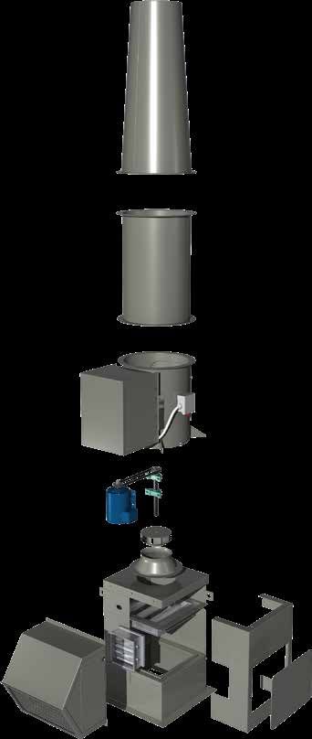
Licenses, Certifications &
Standards, LabCoat™
Licenses and Certifications
AMCA – For Vektor-H performance pages showing AMCA licensed data for Sound and Air
performance, please refer to the Vektor-H Laboratory Exhaust System Performance catalog.
UL 705 Power Ventilator – Vektor-H models are available with the UL/cUL 705 (Underwriters
Laboratory) Listing on a wide variety of 50 and 60-hertz motors. This listing ensures the use
of UL approved electrical components. Motors are available in NEMA totally enclosed, fan
cooled (TEFC), or explosion proof (EXP) designs.
UL 762 Restaurant Exhaust – The Vektor-H, inline grease exhaust fan, is an
alternative for kitchen applications when the requirement for a high plume rise
is deemed necessary. The Vektor-H with the UL 762 grease option is designed
to withstand the demands of high temperature kitchen grease exhaust.
                                                                                                                                 Model Vektor-H is available
UL 762 is concerned with fans designed for removal of smoke and grease                                                           with the UL/cUL 705
laden vapors.                                                                                                                    Electrical Listing
                                                                                                                                 File #E40001
High Wind – The Vektor-H has also been tested and certified by an
independent third party to meet the hurricane and high wind standards of the
Miami Dade Building Code Compliance Office, the Florida Building Council and
the Texas Department of Insurance (TDI).
                                                                                                                            Model Vektor-H is available
Complete certification reports can be found on the Miami-Dade website for                                                   with the UL 762 Listing
the Notice of Acceptance (NOA) number 19-0520.03 (www.miamidade.gov),                                                       (Power Ventilators for
                                                                                                                            Restaurant Exhaust
the Florida Building Code website for the Florida Product Approval number                                                   Applications) Maximum
FL17237 (www.floridabuilding.org), or the Texas Department of Insurance                                                     Operating Temperature 400ºF
                                                                                                                            File #MH11745
website under TDI number RV88 (www.tdi.texas.gov).

LabCoat™ Corrosion-Resistant Coating
Components are electrostatically powder-coated with LabCoat, a two-part corrosion-resistant epoxy coating.
The standard color is RAL 7023 Concrete Grey. Optional colors are available upon request.
• Step 1: Advanced surface preparation
  (8-stage chemical wash)
• Step 2: An epoxy primer is applied and                                                 LabCoat Cross Section
  partially cured
                                                             Two Coat Process                                             Epoxy Primer
• Step 3: The finish coat of polyester resin
  (Hi‑Pro Polyester) is applied and then fully                              Topcoat
  cured at 400ºF
                                                                            4-6 mils Total                                            Advanced
LabCoat is not affected by the UV component                                                                                  Surface Preparation
of sunlight (does not chalk), and has superior
corrosion resistance to acids, alkalis, solvents
                                                                                                Base Steel
and harsh environments (high humidity, coastal
applications). The LabCoat system exceeds
4000 hour ASTM B117 Salt Spray Resistance.

LabCoat Test Data
       Salt Spray ASTM B117                            Durability                             Chemical Resistance Ratings
                                                  Pencil      Cross-Hatch                    Sulfuric
     Hours         1000   2000   3000   4000                                                                 HCI                       Chlorine         NaOH
                                                Hardness       Adhesion         Bleach         Acid                        MEK
                                                                                                            (10%)                       (0.1%)          (20%)
                                               ASTM D3363    ASTM D3359-B                     (10%)
Permatector™                                      3H           No Failure          0             0             0             1            0              1
Hi-Pro Polyester                                  2H           No Failure      0 - No effect
LabCoat                                           2H           No Failure      1 - Slight change in gloss or color
                                                                               2 - Surface etching, severe staining, but film integrity remains
                                                                               3 - Significant pitting, cratering, swelling, or erosion with obvious
                                                                                    surface deterioration

4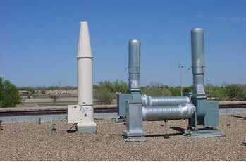
Standard Construction
Features and Options
1   Nozzle - High velocity, conical discharge nozzle reduces system effects associated with a
    quick or abrupt reduction in the discharge stack diameter.
2   Extension - Standard component on sizes 9 through 22 to increase the overall system
    height to a minimum of 10 ft (3 m) above the roof deck. The extension is manufactured
    from welded steel and coated with LabCoat.
3   Motor Cover - Designed to protect the motor and drive components from rain,
    moisture, dust, and dirt. The motor cover is manufactured from welded steel and
    coated with LabCoat.
                                                                                                             1
4   NEMA-3R Toggle Disconnect Switch - Factory mounted and wired NEMA-3R switch
    is available to disconnect power before performing field service work.
5   Drives - Belts and sheaves are sized for 200% of motor horsepower with a minimum
    of two belts.
6   Motor - Premium efficient, standard NEMA frame, TEFC motor with 1.0 service factor
    when used with a variable frequency drive (VFD) and 1.15 service factor with across
    the line operation.
7   Wheel - A backward-inclined, non-overloading wheel manufactured of welded
    aluminum and coated with Hi-Pro Polyester.
8   Bypass Air Plenum (optional) - Facilitates the addition of ambient air to the exhaust
    airstream. The additional air increases the dilution of the exhaust air and also                         2
    increases the discharge momentum resulting in greater displacement above the
    roof. On variable volume systems, the bypass air plenum and damper allow the
    reduction of lab exhaust volume by adding ambient air to the exhaust airstream.
    This allows the fan to run at a constant speed without the need for a variable
    frequency drive. Bypass air plenums are constructed of heavy-gauge welded
    steel and are coated with LabCoat.
9   Isolation Damper (optional) - A parallel blade damper used to allow
    maintenance on a fan while others are in operation. The isolation damper also                                     4
    prevents backflow on a redundant fan while the system is operating. Dampers
    are fabricated of steel or aluminum and are coated with Hi-Pro Polyester.
                                                                                            3
    Control options are gravity or electric (2-position, spring return) actuators.
10 Bypass Air Damper (optional) - Opposed blade damper used to bring
    ambient air into the fan system for additional dilution or an increase in plume
                                                                                            5
    rise. Dampers fabricated of steel are coated with Hi-Pro Polyester. Control
    options are electric or a manual quadrant.
                                                                                        6
11 Weatherhood - (included with Bypass Air Damper) Designed to protect the
    bypass air damper and actuator (optional) from rain, moisture, dust, and dirt.
    Weatherhoods are manufactured from welded steel and coated with LabCoat.
                                                                                                7
12 Roof Curb - A structural support fabricated of 14-gauge galvanized/
    galvaneal steel structurally reinforced to provide a minimum wind-                                                    9
    load rating of 125 mph (200 km/hr) without the use of guy wires on
    the installed Vektor-H system.
    Drain Connection - A drain connection located at the bottom of                                  8
    the fan housing allows for removal of any rain or condensation. An
    additional drain (standard) is located at the bottom of the bypass air
    plenum.
                                                                                 11
    Fasteners - All fasteners provided are stainless steel for additional                               10
    corrosion-resistant protection.
                                                                                                                 12
    Spark-Resistant Construction - All size fans are manufactured to
    meet AMCA type “B” spark-resistant construction (aluminum wheel
    and shaft seal).
    Bearings - Air handling quality bearings in excess of L10 -
    100,000 hour bearing life (equal to L50 - 500,000 hrs).
    Nylon extended lube lines allow for fan bearing lubrication.

                                                                                                                              5
Performance
Unit Performance Range (CFM) Nozzle Size Range
Size Minimum Maximum Minimum Maximum
9 270 1,705 4 9
10 420 1,960 5 10
12 600 2,640 6 13
13 810 3,160 7 14
16 1,050 7,080 8 18
18 1,320 7,880 9 19
22 1,650 10,560 10 22
24 2,760 14,760 13 27
30 3,690 19,640 15 30
36 5,310 24,000 17 38
Nozzle Data Effective Stack Height*
Size Outlet Area Outlet Velocity (ft/min.)
(in) (ft²) 3000 3500 4000
4 0.09 13.4 14.0 14.5
5 0.14 14.3 15.0 15.7
6 0.20 15.1 16.0 16.8
7 0.27 16.0 17.0 18.0
8 0.35 16.8 18.0 19.1
9 0.44 17.7 18.9 20.2
10 0.55 18.5 19.9 21.4
11 0.66 19.4 20.9 22.5
12 0.79 20.2 21.9 23.6
13 0.92 21.1 22.9 24.8
14 1.07 21.9 23.9 25.9
15 1.23 22.8 24.9 27.0
16 1.40 23.6 25.9 28.2
17 1.58 24.5 26.9 29.3
18 1.77 25.3 27.9 30.5
19 1.97 26.2 28.9 31.6
20 2.18 27.0 29.9 32.7
22 2.64 28.8 31.9 35.0
24 3.14 30.5 33.9 37.3
26 3.69 32.2 35.9 39.5
27 3.98 33.0 36.8 40.7
28 4.28 33.9 37.8 41.8
30 4.91 35.6 39.8 44.1
32 5.59 37.3 41.8 46.4
34 6.31 39.0 43.8 48.6
36 7.07 40.7 45.8 50.9
38 7.88 42.4 47.8 53.2
* Effective stack height values assume system height of 10 feet, wind speed of
10 mph. Plume rise calculated assuming a 10 mph crosswind. (3,000 ft/min. is
the minimum recommended outlet velocity per ANSI Z9.5.) For a full range of fan
performance, consult the Laboratory Exhaust Systems, Vektor-H Performance
Manual, 00.LAB.NB002 R3 4-2017
Model Number Nomenclature
VEKTOR - H - 24
Lab Exhaust Fan Size
Belt Drive
High Plume Blower
6Dimensional Data
1x1 System - Fan Only 1x1 System with Plenum
Size A B C D G Size A B C D E G
9 122 22 321⁄2 23 56 9 122 215⁄8 40 27 50 29
43.0 43.0 43.0 43.0
10 122 22 321⁄2 23 56 10 122 215⁄8 40 27 50 29
12 122 22 32 ⁄21
23 56 12 122 21 ⁄8
5
40 27 50 29
13 1221⁄2 24 351⁄2 241⁄2 55 13 1221⁄2 235⁄8 45 28 521⁄2 27
16 1221⁄2 28 391⁄2 281⁄2 51 16 1221⁄2 275⁄8 50 30 581⁄2 21
43.0 43.0 A A 43.0 43.0
18 122 34 45 ⁄21
31 48 18 122 33 ⁄8
5
57 31 62 17 G
A G
A
22 1211⁄4 40 54 351⁄4 43 22 1211⁄4 395⁄8 64 34 691⁄4 9
24 122 46 591⁄2 42 37 24 122 455⁄8 71 37 79 —
30 1311⁄2 52 681⁄4 481⁄2 40 D D
30 1311⁄2 515⁄8 79 40 881⁄2 —
A A
36 143 58 741⁄2 54 46 36 143 575⁄8 87 46 100A
G — G
A
E E
B B2.5
Inside Inside 2.5
Square Square D Option B
D Option B
C C Inlet Inlet
D D Position Position
E 2.5 2.5
E
B B
All dimensions
Inside
Square
2.5 are
Inside in inches.
2.5 B
Inside
B
Inside
Square D OptionDB Square
Option B Square
C
A =COverall systemCheight (less curb) Inlet Inlet C
Position Position
Option A
B = Length of curb cap (inside dimension) Inlet
Option A
Inlet
C = Width of curb cap (inside dimension) 2.5 2.5 Position Position
D = Width of plenum (including weatherhood) B B
Inside Inside
E = Height of plenum C
Square
C
Square
F = Height of plenum and fan (less curb cap) Option A Option A
G = Height of stack extension Inlet Inlet
Position Position
2x1 System with Plenum 43.0 43.0 3x1 System with Plenum
43.0 43.0 43.0 43.0
G G
A A
G G G G
A A F F A A
3.25 3.25 3.25 3.25
Option B Option B
E EInlet Inlet
Position Position
F F 2.5 F F
2.5
3.25 3.25 3.25 3.25
Option B Option
C B C Option B Opti
C
B E B Inlet E Inside B BE Inlet E
Inside Inlet Inside Inside In
Insid
Inside Position Inside Position
D Position D D Pos
Option A Option A Optio
Inlet Inlet Inle
2.5 2.5 Position Position 2.5 2.5 Posit
B C C C C
B Inside Inside B B
Inside Inside Inside Inside Inside Inside
D D D D
Option A Option A Option A Option A
Inlet Inlet Inlet Inlet
Position Position Position Position
Size A B C D E F G Size A B C D E F G
9 122 48 ⁄2
1
21 ⁄8
5
40 27 50 29 9 122 75 ⁄8
3
21 ⁄85
40 27 50 29
10 122 481⁄2 215⁄8 40 27 50 29 10 122 753⁄8 215⁄8 40 27 50 29
12 122 481⁄2 215⁄8 40 27 50 29 12 122 753⁄8 215⁄8 40 27 50 29
13 1221⁄2 521⁄2 235⁄8 45 28 521⁄2 27 13 1221⁄2 813⁄8 235⁄8 45 28 521⁄2 27
16 1221⁄2 601⁄2 275⁄8 50 30 581⁄2 21 16 1221⁄2 933⁄8 275⁄8 50 30 581⁄2 21
18 122 721⁄2 335⁄8 57 31 62 17 18 122 1113⁄8 335⁄8 57 31 62 17
22 1211⁄4 841⁄2 395⁄8 64 34 691⁄4 9 22 1211⁄4 1293⁄8 395⁄8 64 34 691⁄4 9
24 122 961⁄2 455⁄8 71 37 79 — 24 122 1473⁄8 455⁄8 71 37 79 —
30 1311⁄2 1081⁄2 515⁄8 79 40 881⁄2 — 30 1311⁄2 1653⁄8 515⁄8 79 40 881⁄2 —
36 143 1201⁄2 575⁄8 87 46 100 — 36 143 1833⁄8 575⁄8 87 46 100 —
7Family of Lab Exhaust Systems
High Plume - Effective means of creating a discharge plume height to prevent re-entrainment of chemical exhaust
fumes into make-up air systems.
Vektor-H Vektor-MH Vektor-CH
• High plume discharge nozzle • High plume nozzle • High plume nozzle
• Centrifugal wheel • Mixed flow wheel / • Centrifugal wheel
• Compact design / sealed bifurcated housing • Up to 56,000 cfm
airstream components • Compact design and 12 in. wg
• Up to 26,000 cfm and 4 in. wg • Up to 47,000 cfm
and 11 in. wg
High Plume Dilution - Fan design that entrains and mixes outside ambient air into the exhaust airstream prior to
exiting out the windband discharge. Potentially hazardous exhaust or exhaust fumes are diluted and dispersed quickly.
Vektor-MD Vektor-CD
• High plume discharge nozzle • High plume discharge nozzle
with entrainment and dilution with entrainment and dilution
• Mixed flow wheel / bifurcated housing • Centrifugal wheel
• Compact design • Highest efficiency / easy service design
• Up to 83,000 cfm and 11.5 in. wg • Up to 122,000 cfm and 13.5 in. wg
High Plume Variable Geometry Nozzle (VGN) - The discharge area automatically adjusts to maintain
a constant discharge velocity and remain compliant to design codes. VGN maximizes effective plume heights during
periods of reduced flow and lower discharge velocity fixed nozzles.
Vektor-HS Vektor-MS Vektor-CS
• VGN discharge • VGN discharge • VGN discharge
nozzle technology nozzle technology nozzle technology
• Variable volume flow – • Variable volume flow – • Variable volume flow –
constant velocity discharge constant velocity discharge constant velocity discharge
• Centrifugal wheel • Mixed flow wheel / • Centrifugal wheel
• U p to 26,000 cfm bifurcated housing • Up to 32,000 cfm
and 3.5 in. wg • Up to 32,000 cfm and 10 in. wg
and 10 in. wg
Our Commitment
As a result of our commitment to continuous improvement, Greenheck reserves the right to change
specifications without notice.
Product warranties can be found online at Greenheck.com, either on the specific product page or in the
literature section of the website at Greenheck.com/Resources/Library/Literature.
00.LAB.1001 R8 7-2020
P.O. Box 410 • Schofield, WI 54476-0410 • Phone (715) 359-6171 • greenheck.com Copyright © 2020 Greenheck Fan Corp.You can also read