2010+ Camaro "Triple-Threat" Wet Nitrous System
←
→
Page content transcription
If your browser does not render page correctly, please read the page content below
2010+ Camaro “Triple-Threat” Wet Nitrous System
    This Installation Guide is to be used with the Ny-Trex Owner’s Manual.
(Refer to the Owner’s Manual for installation tips, safety tips, and precautions)

1. Remove power Disconnect negative battery cable from battery terminal; then do the same with
   the positive cable. Note: the battery is located in the trunk- where a spare tire would apparently
   reside. Next, disconnect the Engine Control Module (ECM) connectors located in the engine bay,
   on the passenger side, next to the fuse box (figure 1).

2. Remove Engine Cover Remove oil fill cap and lift front of plastic cover to remove. Unlock the
   clips to remove the “soft” cover (figures 2 & 3).

3. Assemble Throttle Body (TB) Plate, Nozzle assembly, and lines Assemble the throttle body
   plate (10), nozzle (11), jets (8), 90° nozzle adapters (16), and 12” nozzle lines (8). Insure nozzle
   outlet hole and lines are configured as shown in figure 4. Note: Only use thread sealer (19) on
   NPT fittings- never use on flare fittings!

4. Install TB Plate Assembly Remove air intake tube from throttle body (TB) and air box. Discon-
   nect TB wire harness and loosen/remove TB bolts. Remove and discard OEM TB gasket. Using
   longer TB bolts/washers (18) and gaskets (17), attach Ny-Trex TB plate assembly to intake mani-
   fold- braided lines should go toward passenger’s side. Note: two new gaskets should be placed on
   either side of TB plate on 2010-2011 vehicles; 2012+ only require one gasket on TB side of plate.
   Re-connect wire harness and re-assemble air intake tube.

5. Mount Camaro Triple-Threat Assembly Loosen and remove bolt which retains water pipe on
   passenger’s side cylinder head (figure 5). Install the Triple-Threat assembly on top of this pipe
   bracket with OEM bolt (figure 6). Connect the nozzle lines to the appropriate fittings on the Triple-
   Threat valve. Note: the red fuel line connects to the rear fitting, and the blue nitrous line to the
   middle fitting (figures 7 & 8).

6. Connect Fuel Supply Line Remove the service cap from the fuel pressure Schrader valve at
   back of engine near the firewall (figure 9). Place a shop rag around the valve fitting to catch and
   contain escaping fuel. SLOWLY start to remove the Schrader valve, letting the fuel that is still un-
   der pressure seep out and soak into the rag. This will depressurize the fuel system. When the sys-
   tem is depressurized, completely remove the valve. Retain and store the valve for future re-
   installation. Install the 90° fuel supply adapter (15) with the outlet clocked toward the passenger
   side front wheel (figure 10). Connect the fuel supply line (6) to the adapter and route the line over
   the valve cover to the Triple-Threat valve (figure 11). Connect the loose end of the line to the blue
   rear-facing fitting on the Triple-Threat valve. Tighten both ends of line.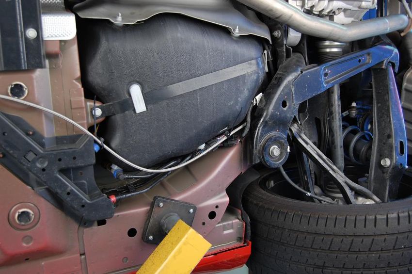
7. Install Engine Bay Electrical System Remove fuse box cover, located in engine bay just behind
passenger side headlight. Remove the nut on the positive terminal, located immediately in front of
the fuse box (figure 12). Install the eyelet connectors from the Triple-Threat valve harness to the
terminal and reinstall the nut (figure 13). Connect and install the engine to passenger bay exten-
sion cable (5). It should be routed from the fuse box vicinity to the firewall, following the wire
harness that passes over the passenger side strut tower. Unlock the plastic cowl cover clips and
lift the cover (figure 14). Route the wire to the driver side of the car in the cowl channel. Exit cowl
and pull wire through the firewall utilizing one of the available grommets under the brake booster,
providing access to the driver’s foot area. Fasten all loose wire with zip ties (9).
8. Install Passenger Compartment Electrical System Locate and remove the bottom-right bolt
on the accelerator pedal assembly and place the WOT bracket/switch over the revealed hole. In-
sert the bolt into the wire eyelet on the supplied passenger bay harness (4). Then insert the bolt
into the bracket and pedal assembly (figure 15). Adjust bracket/switch assembly down and to the
right (figure 16); tighten bolt assuring its proper orientation. Test for proper operation and adjust
if necessary. Route the remaining wiring and components toward the location at which the activa-
tion and purge button will be installed. Note: improper installation may result in faulty activation.
9. Install the Purge Button and Activation Switch Location of these controls is determined by
owner/installer preference. Any location within easy reach of the driver is acceptable. Note: many
Ny-Trex customers fabricate a small switch panel which can be placed in the cup-holder/ash tray
compartment. After switches have been installed, connect the remaining two connectors from the
passenger bay electrical components to the extension cable. Hide and tie all access/loose wire un-
der the dash utilizing zip ties (9).
10.Install Purge Components Locate a preferred point at which the v-spray purge block should be
mounted. Note: the aluminum tubing (7) is 3 feet long, so choose a location accordingly. Connect
the aluminum line to the v-spray purge block utilizing the brass compression fitting. Thread sealer
(19) may be used on the brass fitting to purge block connection. Mount the purge block. Route
the aluminum tubing to the fitting labeled “PURGE OUT”, on the Triple-Threat valve. Connect to
fitting and tighten. See figures 17 - 20 for examples of a suitable and stylish location.
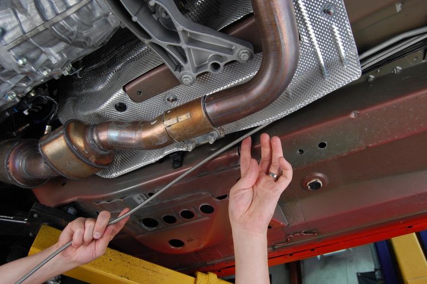
11.Initialize Nitrous Supply Line Routing Refer to page 10 of the Owner’s Manual for details, tips,
and precautions. Lift the trunk compartment carpeting on the right side and fold to the left, ex-
posing trunk pan (figure 21). Remove black plastic plug and feed line through the hole (figure
22). The line will exit just above muffler. Pull majority of line through the pan.
12.Mount the Nitrous Bottle Note: carefully consider the carpeting and what the owner/installer
prefers while progressing through the steps to install the bottle. Mounting the bottle on top of the
carpeting will require drilling and or cutting, while leaving the carpeting folded back requires none.
Mount the bottle brackets (2) to bottle (1) as described on page 10 of the Owner’s Manual. Place
the bottle on the trunk pan, as illustrated (figure 23). Mark holes with permanent marker (figures
24, 25, 26) Note: bracket might need to be outlined first; then removed from bottle to locate and
mark holes. Drill holes with a pilot bit initially and then follow with a ½” bit. Install well nuts (14)
into the four holes. Place bottle (with brackets) over the holes. Install bolts (14) and tighten.
13.Completing the Nitrous Supply Line Routing Determine the best suited path. Avoid routing
line near all hot components- mufflers and exhaust in particular. Following the fuel lines and tuck-
ing the line behind the aluminum heat shield (removing and replacing fasteners where necessary)
is advised. Utilizing plastic zip ties (9), fasten line to fuel lines, wire harness, or other suitable lo-
cations intermittently along route. Just after the line passes the ECM, start the upward turn to-
ward the Triple-Threat valve (figures 27-34).
2
14.Attach Supply Line to Triple-Threat Valve Route supply line to the “N2O IN” fitting on the
   front-most side of the Triple-Threat valve (figure 35). Connect to fitting and tighten. Carefully
   track the route of the supply line, insuring that the line is secure and appropriately fastened. Clip
   excess off each zip tie.

15.Test the Solenoids Be sure the nitrous bottle is FULLY CLOSED and no pressure is in the N2O
   supply line. Because this complete system utilizes a fuel safety switch, a jumper must be placed
   across the “NO” and “C” terminals while testing the solenoids. Reconnect the ECM and then the
   battery. To test the system, turn the arming toggle switch ON, and quickly depress and release
   the accelerator pedal, toggling the WOT switch. A clicking sound should be heard as the solenoids
   activate. Test the purge solenoid by quickly pressing and releasing the red purge switch. Again, a
   clicking sound should be heard as the purge solenoid activates.

16.Check All Components With feed lines and electrical connections completed and nitrous supply
   line connected to the bottle, FULLY open the bottle valve and carefully check connections on the
   nitrous side of the system for leaks. Re-tighten fittings if necessary. With no leaks detected, start
   engine and thoroughly check fuel connections for leaks. Again, re-tighten fittings if necessary.

17.Re-install All Loose Parts If everything is in proper working order, re-install both engine covers.
Re-install all cowl clips. Re-install fuse box cover. Scan vehicle to see that nothing was missed or for-
gotten.

    18. INSURE THAT TRACTION CONTROL IS DEACTIVATED BEFORE USE!
   2010+ Camaros utilize a Drive-By-Wire throttle system; the throttle body is not mechanically con-
   nected to the throttle plate. To control wheel-spin, the Camaro’s ECM will close the throttle and
   cut fuel proportionally. The activation of this Ny-Trex nitrous system is directly associated with
   pedal position; there is no connection to the ECM or the vehicle’s Traction Control System (TCS).
   Nitrous oxide cannot be used while the TCS is activated. To disabled the TCS, depress the
   “StabiliTrak” button located just in front of the transmission shifter lever, and hold it for seven se-
   conds (figure 36). Amber warning symbols, similar to those below, will be displayed on the right
   side of the instrument cluster (just inside the tachometer) when the TCS has been fully disabled.
   WARNING: when vehicle is shut off and restarted again, the TCS is automatically activated. It
   must again be disabled for use of the nitrous system. So...ALWAYS CONFIRM THAT THE TCS
   IS DEACTIVATED BEFORE UTILIZING THE NITROUS OXIDE SYSTEM!

                                                     3
Component Overview                                                                                                                                                                    Fig. 35

                  Triple-Threat Camaro 5 (2010+) V6 EFI Wet Nitrous System
                                      2                       1
                                                                                              2

              3                                      6             10                                12

                                                 7                                                                  18
                                                              11
                                                 8

                                                                                                                         19
                                          5                                                                         13
                                                                                                                                                                                              Fig. 35
       4                                                                                                             14

                                                         9                     17                     15      16

ITEM       DESCRIPTION                                       QTY        ITEM        DESCRIPTION                          QTY
1          Assembled Nitrous Bottle                           1         11          N-T Nozzle                            1
2          Bottle Brackets                                    2         12          14' Nitrous Feed Line                 1
3          Camaro Triple-Threat Assembly                      1         13          Jet Assortment                        8
4          Passenger Bay Electrical Components               Set        14          Installation Hardware                Set
5          Engine to Passenger Bay Extension Cable            1         15          90° Fuel Supply Adapter               1
6          Fuel Supply Line                                   1         16          90° Nozzle Adapters                   2
7          Purge Components                                  Set        17          Throttle Body Gaskets                 2
8          12" Nozzle Lines                                   2         18          Throttle Body Bolts & Washers        Set
9          Zip Ties                                           20        19          Thread Sealer                         1
10         Throttle Body Plate                                1

                                                                                                                               Ny-Trex, DEI Contact: Sales@DesignEngineering.com, Ph: 440-930-7940 Fax: 440-930-7967
                                                                   4                                                                                                       17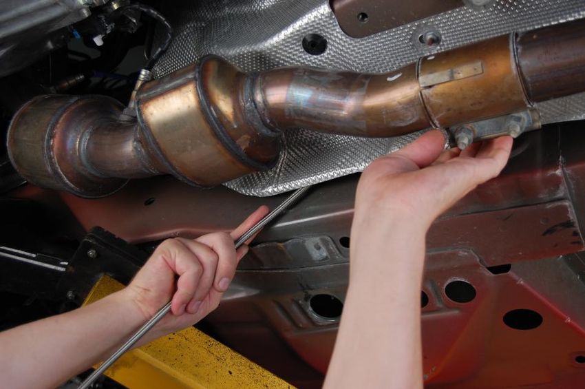
Fig. 33   Fig. 1                         Fig. 2

                        Fig. 3                Fig. 4

     Fig. 34

                                     Fig. 5

16                               5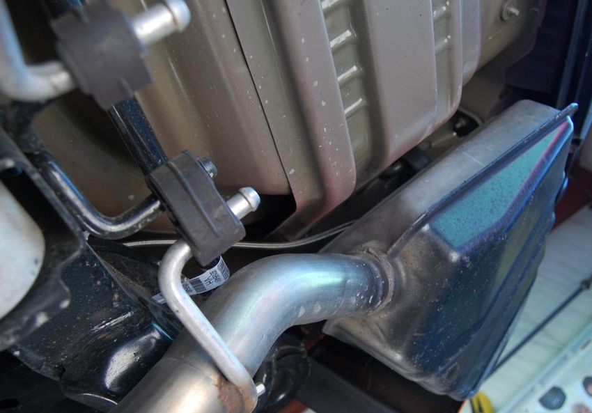
Fig. 6                Fig. 7           Fig. 31

                                           Fig. 32
Fig. 8                       Fig. 9

                 Fig. 1

             6                        15
Fig. 29   Fig. 10            Fig. 11

     Fig. 30
                    Fig. 12

                                  Fig. 13

14                            7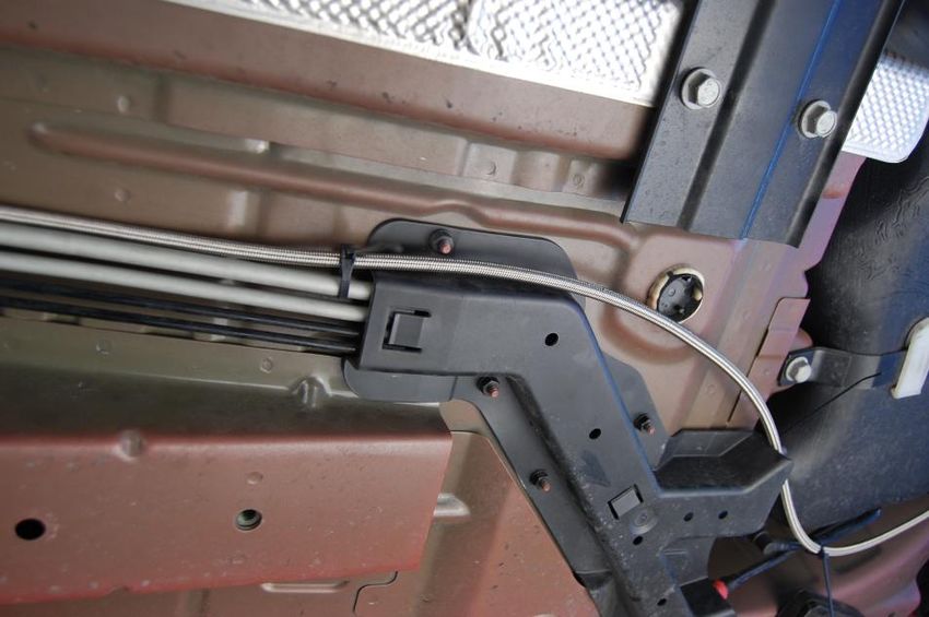
Fig. 14                         Fig. 27

    Fig. 15                    Fig. 16

                                              Fig. 28

                   Push WOT switch
                         ↓down and
                        →to the right

8                                        13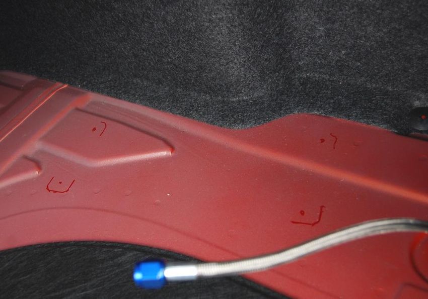
Fig. 25                 Fig. 17

     Fig. 26

                   Fig. 18

12             9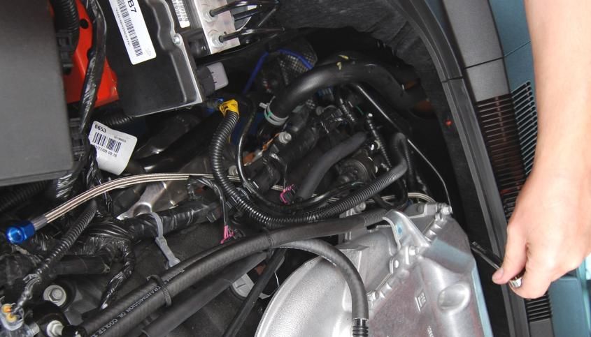
Fig. 19   Fig. 21                  Fig. 22

                              Fig. 23

     Fig. 20

                              Fig. 24

10                       11
You can also read