CONTRACT NO. WM20/21-02 - 2021 Leachate Pond Primary Geomembrane and Floating Cover Replacement BACKGROUND REFERENCE DOCUMENT FOR
←
→
Page content transcription
If your browser does not render page correctly, please read the page content below
BACKGROUND REFERENCE DOCUMENT
                 FOR

         CONTRACT NO. WM20/21-02

2021 Leachate Pond Primary Geomembrane and
         Floating Cover Replacement

                     LANE COUNTY
      PUBLIC WORKS - WASTE MANAGEMENT DIVISION
                 3100 EAST 17TH AVE.
               EUGENE, OREGON 97403

                       Expires 06/20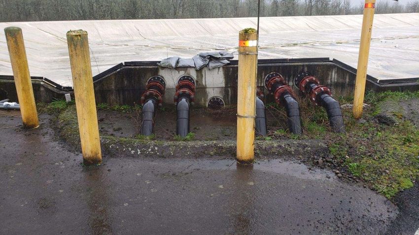
TABLE OF CONTENTS

                                                      PAGE

DESCRIPTION OF WORK……………………………………………………………………….1

BACKGROUND…………..……………………………………………………………………….1

DESIGN INTENT………………………………………………………………………………….3

PHOTOS OF EXISTING FLOATING COVER AND ANCHOR WALL …………………….3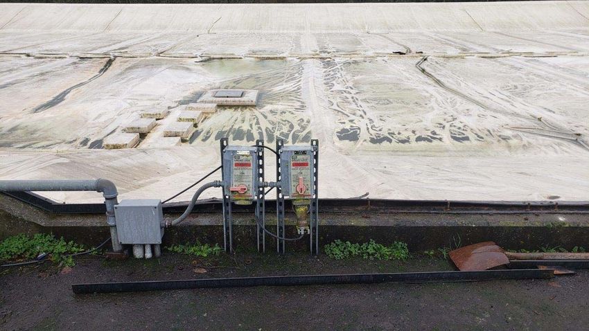
DESCRIPTION OF WORK

                              Contract No. WM20/21-02
      2020 Leachate Pond Primary Geomembrane and Floating Cover Replacement

Perform the following general scope of work on 1.5 ac pond (65,544 sq ft): remove and dispose
of existing floating cover system into onsite landfill; remove estimated 500,000 gallons of sludge
and liquid from pond and dispose into onsite landfill; clean existing pond liner and perform
electric leak survey on existing conductive liner; install new 80-mil smooth conductive HDPE
geomembrane over the top of existing liner and perform electric leak survey; install new 60-mil
RPP floating cover system with all appurtenances; and all other work called for in the plans and
specifications. Project is located at the Short Mountain Landfill, 84777 Dillard Access Road,
Eugene, Oregon 97405.

                                         BACKGROUND

The existing leachate pond at the Short Mountain Landfill was constructed in 1998. The pond
size is 1.5 acres, with a rectangular shape having rounded corners. The maximum pond depth
from crest to sump is 13 feet. The interior side slopes are 3:1. The bottom slope is 4% with
minimum 2% slopes hinge lines.

The original bottom liner system is two layers of 60-mil conductive HDPE with an intervening
geonet leakage collection layer. The bottom of the pond has a secondary riser pipe that allows
monitoring and removal of any leakage through the primary geomembrane. The current
leakage rate that the pond experiences, averaged over a one year period, is about 25 gallons
per day. Removal of leachate from the pond occurs through a vertical pipe penetration in the
sump that conveys the leachate to a pump station. Leachate inlet into the pond come in
through pipes over the top of the liner system perimeter anchor.

The secondary geomembrane is terminated around the perimeter by an extrusion weld to a
concrete embedment strip in the perimeter concrete anchor wall. The primary geomembrane is
extrusion welded to the secondary geomembrane about 4 inches behind the embedment strip.

To eliminate rainwater from directly falling into the pond, which would have to be treated as
leachate, the pond was fitted with a floating cover. The floating cover system was/is comprised
of a 45-mil reinforced polypropylene geomembrane with a system of floats, weight tubes,
hatches, and a weighted stormwater sump. The stormwater is pumped from the surface of the
floating cover.

The performance of the bottom liner system and floating cover system has been exemplary for
21 years. At this time, however, it is clear from cracking in the polypropylene geomembrane
that the resin is at the end of its life, and the floating cover needs to be replaced. This need
is the primary driver for doing this project.

Since the floating cover will be removed for the first time since its construction 21 years ago, this
will also be an opportune time to remove any accumulated sludge from the pond. Cleaning the
sludge and removing the leachate will also provide a clean working surface for installing the
new membrane liners.
                                                 1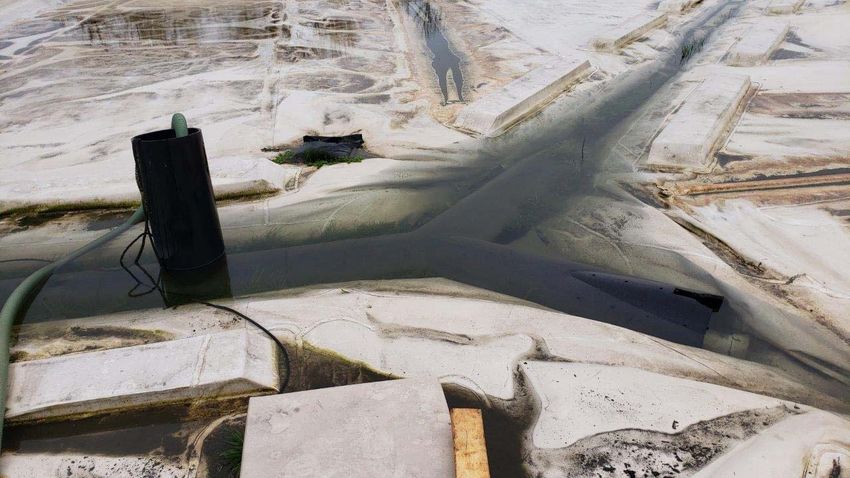
Even though the existing primary and secondary geomembrane pond liner appear to be
performing very well at containing the leachate, the removal of the floating cover affords the
opportunity to make any desired modifications to the existing liner system. The owner has
decided that since the geomembranes are over 20 years old, it would be prudent to over-line the
existing primary geomembrane with a new primary geomembrane. Installing a new primary
geomembrane also necessitates some means of relieving any gases and liquids that might
become trapped between the new and old geomembranes. Such measures have been
incorporated into the new design, described below.
DESIGN INTENT
2021 LEACHATE POND PRIMARY GEOMEMBRANE AND FLOATING COVER
REPLACEMENT
Key design intents for this project include the following:
The existing integrity of the existing 60-mil HDPE primary geomembrane liner
shall be maintained. The existing primary geomembrane has some important
penetration seals around the outlet and the secondary riser pipe. Also its existing
integrity is a valuable source of redundancy. Therefore it is the design intent that the
Contractor shall take special care not to damage the existing geomembrane during
cleaning and over-lining activities. Before the installation of the new primary
geomembrane, the contract documents will require the conductive liner to be electrically
surveyed for defects, and any found defects to be repaired. The Special Provisions do
not allow cutting of any materials with razors above the existing geomembrane without
the presence of 60-mil or thicker rubsheets. This will be enforced.
The new geomembrane shall be a conductive smooth black (or white surfaced) 80-
mil HDPE. Trial welds shall be conducted between the new material and samples taken
from the existing pond. The sampling areas shall be near the crest and shall be
patched.
A new leakage detection and removal riser will need to be installed, necessitating
a localized modification of the perimeter anchor wall. A limited leakage collection
layer piping system is designed to be installed between the existing and new primary
geomembranes. Also, gas vent holes need to be cut with hole saws (perfectly round
with no angular corners) at the high end to allow trapped gasses to vent. The
modifications to the anchor wall will necessitate the Contractor to provide and install
some amount of new batten bar assembly for the floating cover.
The new geomembrane shall be electrically tested for leaks. Leakage of leachate
into either the existing secondary leachate collection and removal system, or the new
leakage collection system between the new and existing primary geomembranes, shall
be less than 50 gallons per day when the pond is in operations (current leakage rate
averages approximately 25 gallons per day before construction began). This leakage
rate is estimated to be the likely result of the occurrence of one “small hole” defined as
having a diameter of 1/32”; or a total of four pinholes, defined as having a diameter of
1/64”; or some other combination of minor defects that would occur in the
geomembranes under an average operating head of 6 feet of liquid. Contractor shall
remedy leakage rates greater than this at no extra cost to Owner.
2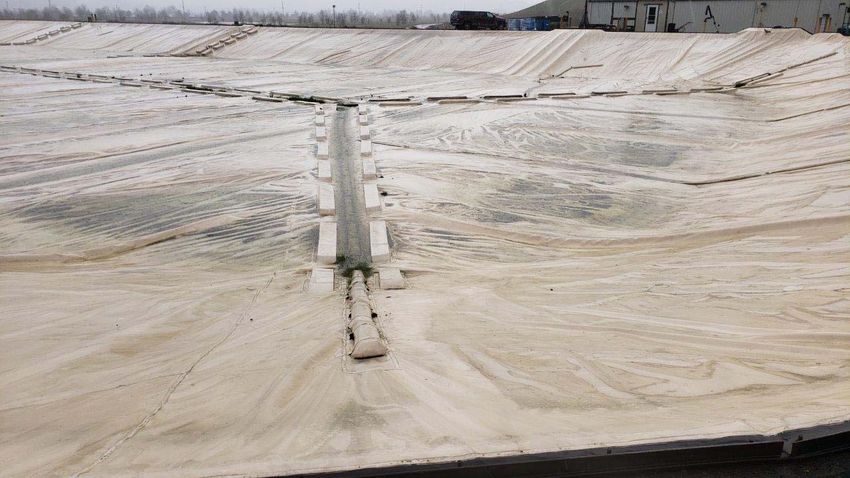
Some elements of piping and weight tubes on top of the existing primary
geomembrane will need to be removed and later replaced to allow installation of
the new primary geomembrane. All costs associated with this work are to be included
in the bid.
When removing the existing floating cover system for demolition, the contract assume
that the following elements shall be salvaged: batten bar, stormwater sump
assembly and pump, and hatches. All other elements shall be discarded and replaced
with new materials. The contactor, at its option, may replace any of the intended
salvage items with new materials, but at no extra cost. Note that the base bid
assumption assumes that 96% of the existing ½” dia anchor bolts are re-usable, and the
6% may need to be ground off, redrilled, and epoxy set. In addition there are two
locations where new batten bar assemblies are required to be supplied and installed by
the Contractor: (1) where the anchor wall has to be raised to accommodate the new riser
pipe, and (2) where the new primary geomembrane will liner over the top of the
secondary rise pipe and need to be vertically battened to the inside of the anchor wall.
For the hatches, only the aluminum frames and covers will be salvaged; new floats shall
be provided for the hatches.
The design intent is that the original floating cover design shall be replicated.
Hence the design is based on markups of the 1999 ‘record drawings’, and no new
design drawings are being provided. The most significant change in the floating
cover to the original design is that the new cover is being specified as 60-mil reinforced
material, whereas the original was only 45 mils.
There are new project specifications for the supply and installation of the
geosynthetics, contained in the Special Provisions.
The project must be completed before the end of August. It is not acceptable for the
County to go into the next rainy season without this project being complete. The County
will intent to enforce the schedule and apply liquidated damages in full measure to
ensure this schedule is met.
PHOTOS OF EXISTING FLOATING COVER AND ANCHOR WALL
In lieu of requiring a mandatory pre-bid meeting, it was deemed expedient to provide a series of
photos showing existing site conditions. Even so, prospective bidder are welcome to visit the
site ahead of time by contacting Jesse Berger as described in the bid documents.
Photos on following pages.
3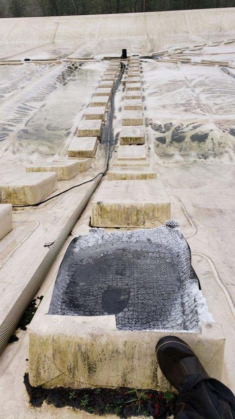
STANDING ON MIDDLE OF NORTH SIDE LOOKING SW

LOOKING ACROSS POND N-S AT LOCATION OF BROKEN SIDE WEIGHT TUBE CABLE

                                  4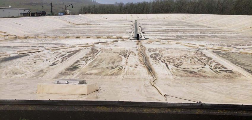
LOOKING N-S ON WEST END OF POND TOWARDS STORMWATER SUMP

AT NW CORNER LOOKING SE TOWARDS STORMWATER SUMP

                                 5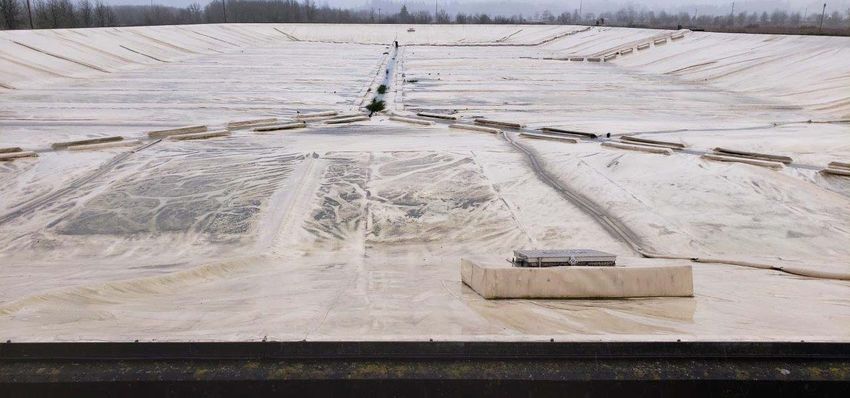
AT WEST END CENTER LOOKING EAST

AT SE CORNER LOOKING NW. THERE IS NO SUMP AT THAT ‘Y’.

                                    6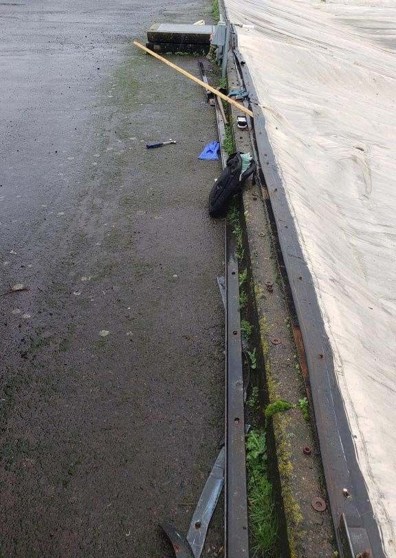
AT EAST END LOOKING WEST

POND INLETS GOING THROUGH ANCHOR WALL NEAR NE CORNER

                                 7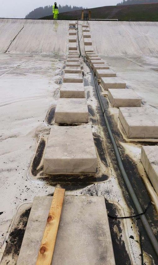
LOADOUT INLET DRAINS ON NORTH SIDE

CENTER NORTH SIDE LOOKING AND ELECTRIC JUNCTIONS AND HATCH ABOVE POND
SUMP

                                     8
STANDING ON HATCH FLOATS AND VIEWING LEACHATE INSIDE OPEN HATCH. THE
HATCH MECHANISMS SEEMED TO WORK VERY WELL. A SOUNDING OF THE
LEACHATE AT THIS LOCATION WITH A 1X4 TO THE POND BOTTOM DID NOT INDICATE
THE PRESENCE OF ANY SLUDGE.
PREPARING TO WALK DOWN FLOATS TO STORMWATER SUMP. THE LINER FROM
THE TOP FLOAT HAD BEEN CUT OFF FOR SAMPLING AND TESTING
9STANDING AT STORMWATER SUMP LOOKING BACK TO THE NORTH
STANDING AT STORMWATER SUMP LOOKING EAST
10STANDING AT STORMWATER SUMP TO SW CORNER
STANDING AT STORMWATER SUMP TO NW CORNER
11STORMWATER SUMP
VIEW OF CRACKED RESIN ON FLOATING COVER
12ON NORTH SIDE LOOKING EAST. NOTE REMOVED BATTEN BAR
TYPICAL VIEW UNDER FLOATING COVER NEXT TO ANCHOR WALL ON NORTH SIDE
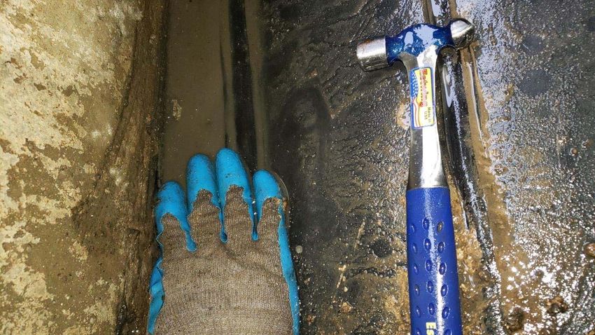
13VIEW UNDER FLOATING COVER NEXT TO ANCHOR WALL SHOWING EXTRUSION
WELD UNDER GLOVE OF SECONDARY GEOMEMBRANE TO EMBEDMENT STRIP. THE
EXTRUSION WELD UNDER THE HAMMER IS THE PRIMARY GEOMEMBRANE TO THE
SECONDARY GEOMEMBRANE. THE INTENT IS FOR THE NEW PRIMARY
GEOMEMBRANE TO BE WELDED BETWEEN THESE TWO WELDS TO THE EXISTING
SECONDARY GEOMEMBRANE. THE INSIDE OF THE ANCHOR WALL WAS STRUCK
WITH HAMMERS AND CROW BARS AND THE CONCRETE FOUND TO BE VERY SOUND.
THERE WERE NOT PARTICULARLY STRONG ODORS OR NOXIOUS SMELLS BELOW
THE COVER
14BATTEN BARS REMOVED AND FLOATING COVER BEING PRYED AWAY FROM
ANCHOR BOLTS ON EAST END
15CONDITION OF EXISTING GEOMEMBRANES AND CONCRETE ANCHOR WALL ON EAST
END APPEARED SIMILAR TO NORTH SIDE: VERY GOOD CONDITION. CONCRETE WAS
SOLID AND HARD.
16REMOVAL OF ANCHOR BOLTS ON SOUTH SIDE
17EXAMPLE OF ‘BATTEN DETAIL USING EX. ANCHOR WALL’ REPAIR SHOWN ON DETAIL
1 OF DRAWING C26 FROM 1999 ON SOUTH SIDE. REASON FOR REPAIR IN 1999 IS NOT
KNOWN, BUT IT APPEARS IN GOOD CONDITION AND NEW PRIMARY GEOMEMBRANE
WELD COULD OCCUR JUST IN FRONT OF THIS.
EXAMPLE OF ‘BATTEN DETAIL USING 12” CONCRETE BLOCK’ REPAIR SHOWN ON
DETAIL 2 OF DRAWING C26 FROM 1999 ON SOUTH SIDE. REASON FOR REPAIR IN
1999 IS NOT KNOWN, BUT IT APPEARS IN GOOD CONDITION AND NEW PRIMARY
GEOMEMBRANE WELD COULD OCCUR JUST IN FRONT OF THIS.
18BATTENS REMOVED ON WEST END.
AS AT ALL OTHER LOCATIONS, CONDITION OF EXISTING GEOMEMBRANES AND
CONCRETE ANCHOR WALL BELOW FLOATING COVER APPEARED VERY GOOD.
END
19You can also read