Applications of MEMS Actuators in Optical and Ultrasound Imaging Jason M. Zara - ECE Department
←
→
Page content transcription
If your browser does not render page correctly, please read the page content below
Applications of MEMS Actuators in
 Optical and Ultrasound Imaging

          Jason M. Zara
           ECE Department
   Biomedical Engineering Professor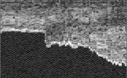
MEMS Devices Developed at Sandia
     National Laboratories

Silicon Gear and Chain –   Spider Mite Crawling on
Chain Links 50 µm Apart    Micro-Mirror Device
Polyimide MEMS Devices for Medical
             Imaging
• Our research group has been working for years on
  applications of polyimide based MEMS devices
  in medical imaging probes
• This work has been done in ultrasound and optical
  imaging applications
• The primary application of these probes is
  endoscopic and catheter based imaging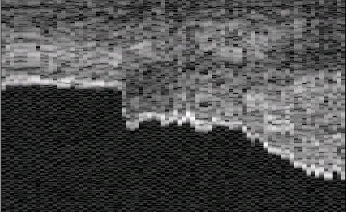
Advantages of MEMS Scanners
• The probe we are developing uses a MEMS actuator to
  mechanically steer a mirror for scanning
• MEMS devices are fabricated using photolithography so
  they can be made to be inexpensive and disposable for
  endoscopic and catheter applications
• Very small devices with low power consumption are
  possible for catheter applications
• Entire scanning mechanism can be contained in tip of
  probe to avoid complications with catheter bending
MEMS Ultrasound Scanning Devices

Modeling and Design of IC
           Fabricated Devices
• Hand-built devices were time consuming to build and
  inconsistent
• Devices needed to be developed that could be fabricated
  on silicon wafers
• Modeling was done with one-dimensional beam models
  and ANSYS finite element analysis
• Devices were then fabricated and tested
• New fabrication methods allow for design of a side
  looking scanner
Schematics of Designed Devices
Forward Viewing Probe Side Viewing Probe
1 mm and 2 mm probes 1 mm and 2 mm probes
IFA
Attachment
Flap
PZT
3 µm Thick Polyimide PZT
Hinges Polyimide
Air Gap
Contact Vias 3 µm Thick Air Gap
Electrical Torsion Contact Vias
Connections Hinges Electrical
Connections
Linear Actuator (IFA) Attached to Table to Sector Ultrasound BeamForward Viewing Devices After Liftoff
2 mm probe
• Devices fabricated with 3-layer
process using photolithography
• 3 µm metallized polyimide layer
1 mm for electrical connection
• 30 µm polyimide layer for table
1 mm probe and rigid supports
• Vias connect top level to
electrical traces
• Liftoff done with HF to remove
1 mm
sacrificial oxide layerSide Viewing Devices After Liftoff
• Devices fabricated with 3-layer
process using photolithography
• 3 µm metallized polyimide layer
2 mm for electrical connection
1 mm
probe • 30 µm polyimide layer for table
and rigid supports
• Vias connect top level to
electrical traces
• Liftoff done with HF to remove
sacrificial oxide layer
1 mm 1 mm
probeMEMS Device Used to Steer Beams:
The Integrated Force Array (IFA)
• Microelectromechanical
System (MEMS)
• Hundreds of thousands of
deformable capacitors
• 2-mask process of
patterned polyimide and
angled metallization
• 1 cm long, 2.2 µm thick
and 1 mm or 3 mm wideIntegrated Force Array Contraction
• Applied voltages create
electrostatic forces which
contract cells in a linear
fashion
• 20 % strains and 13 dyne
forces at 130 Volts
• Scaling down devices
produces equivalent
forces
ε AV 2
Force =
2 L2Assembled Forward Viewing Devices
• 20 MHz piston on 2 mm by 2.25
mm table
• 3 mm wide IFA attached to side of
table
1 mm • Hinges 1.8 mm long and .75 mm
wide
• 30 MHz piston on 1 mm by 1.125
mm table
• 3 mm wide IFA attached to side of
table
1 mm
• Hinges 1.8 mm long and .375 mm
wideAssembled Side Viewing Devices
• 20 MHz piston on 2 mm by 2.25 mm
table
• 3 mm wide IFA attached to side of
table
• Hinges 180 µm wide and 250 µm
1 mm
long
• 30 MHz piston on 1 mm by 1.125
mm table
• 1 mm wide IFA attached to side of
table
• Hinges 90 µm wide and 250 µm long
1 mm30 MHz Forward Viewing Probe and
1 mm Wide IFA
.5 cm
Probe • 4 visible wires
2 mm • Estimated
Scan scan angle
Depth 7.6 degrees
.5 mm
2 cmUltrasound Device Summary • Devices were modeled using FEM and fabricated on silicon wafers • Device scan angles below desired 60° sector angles • Hinge curling, nonlinear stiffening, and fluid damping are major factors in performance shortfalls • Displacements in air were very large, up to 60°, but images were not as successful • The development of new actuators is underway to increase force – thicker IFAs – may be able to overcome fluid problems
MEMS Optical Scanning Devices
Optical Beam Scanner
• In order to take advantage of the large displacements in
  air, devices similar to the ultrasound devices were
  developed as optical scanners
• A gold coated silicon mirror replaces the PZT on the
  table
• Devices have deflected laser beams up to 118º at
  frequencies of 120 Hz
• Could be used to sector laser beams in optical coherence
  tomography (OCT) scanners
Small Optical Scanner
                         Silicon
                         Mirror

                          3 µm
                         Torsion
                         Hinges

                           IFA
                         Actuator

                          30 µm
                          Support
                         Structure

1 mm square mirrors, 1.125 mm wide tables, 1mm wide IFAs
Large Scanning Devices
Gold/Silicon
Mirror
3 µm Thick
Torsion Hinges
IFA
Actuator
30 µm Thick
Support
Structure
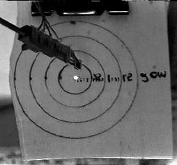
1.5 mm square mirrors, 2.25 mm wide tables, 3 mm wide IFAsScanner Displacements
Calibrated Target Fixed 1.2 cm from Scanner
Small
Scanner at Rest Quasi-Static Near 2nd Resonance
LargeOptical Displacement vs. Frequency
Displacement Vs. Freqency Small Mirror 80 Volts
100
Scan Angle (Optical)
80
60 64° displ. at 31.2 Hz,
40
20
89° displ. at 62 Hz
0
0 10 20 30 40 50 60 70 80
Drive Frequency (Hz)
Displacement Vs. Freqency Large Mirror 80 Volts
160
140
Scan Angle (Optical)
120
77° displ. at 20.6 Hz, 100
80
60
142° displ. at 41.2 Hz 40
20
0
0 10 20 30 40 50 60
Drive Frequency (Hz)Measured Optical Displacements
Scan Angle (degrees)
60
40 Scanner is relatively
20 linear at frequencies
less than 8 Hz
0
50 70 90
Drive Voltage (V) 160
Scan Angle (degrees)
140
120
100
80
77° displ. at 20.6 Hz,
60
142° displ. at 41.2 Hz 40
20
0
0 10 20 30 40 50 60
Drive Frequency (Hz)Optical Coherence Tomography (OCT) • Analogous to ultrasound or radar, but measures reflected infrared light • As small as 4 µm resolution, but only 2-3 mm of penetration in tissue • Has cell level resolution, could be used as an ‘Optical Biopsy’ technique • Applications include eye, skin, intravascular imaging • Most current probes are circular side-scanning, a forward looking probe would have certain advantages – can look ahead of probe and also guide interventional procedures
OCT in Bladder Cancer
• We are currently working with Dr. Michael Manyak
  of the GWUMC Urology Department in a clinical
  trial to investigate the use of OCT in bladder cancer
• For probes to be most useful for this application the
  scan ranges need to be wide and the devices need to
  be robust and predictable
• For this reason we have begun to investigate a new
  way to scan optical beam for endoscopic OCT that
  will be more robust.
OCT Detection of Bladder Cancer
                1.8 mm          1.8 mm

                         U
1.5       LP
               SM                                1.5 mm
mm
                    MS
                             No Defined Tissue
                             Layers
        Normal Bladder
        Tissue               Invasive Tumor
Lateral Scanners in OCT • Lateral scanner is used to move the OCT beam across the target to generate 2-D image • This scanner must be compact for endoscopic and catheter based applications • Clinical endoscopic OCT scanners use spinning wires or push-pull devices • There are certain advantages to a probe that scans in a sector to the front or side of the probe rather than a circular scanning geometry
Endoscopic Scanning Formats
Circumferential Side-Scanning
Scanning Probe Probe
Interventional Interventional
Device Device
360° Scan
Sector
Scan
Other groups have also investigated sector
Many groups have investigated spinning
scanning probes
probes
Boppart et.al. Optics Letters 1997
Tearney et.al. Science 1997
Bouma et.al. Optics Letters 1999
Rollins et.al. Optics Letters 1999
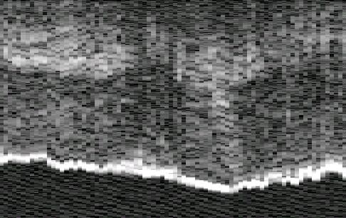
Pan et.al. Optics Letters 2001OCT Images Made With MEMS Scanner
4 mm
Cuticle
Fingernail
4 mm
Stratum Corneum
Sweat
4 mm Stratum Spinosum Gland
Stratum Gemanitivum
4 mmMEMS Scanner in OCT System
Broadband Delay
Optical Source Optical Line
Circulator
I II
Differential
Detector Module 50/50 MEMS
III Fiber and
+ Mirror
Collimator
Σ
-
Operator Controls
Lens
Envelope Sample
Frame Computer
Detector Grabber
Display/Recording
MEMS scanner integrated into scanning arm of OCT scanners, system
is different for galvanometer based scannerIntegration Into Slow OCT System
• The MEMS based scanners were initially integrated into the
scanning arm of a galvanometer based OCT system and used
to make in vivo images of human fingers at imaging rates of
less than 1 Hz
System Specifications
• Light source •Galvanometer based system
– Super luminescent diode (SLD)
–Reference arm displaced by
• FWHM bandwidth - 28.1 nm mirror mounted on galvanometer
• Center frequency - 1288.8 nm - images obtained at a rate of 2-3
• Coherence length - 20.2 µm seconds per image
• 3 mWatts power delivered to –104 dB dynamic range
targetIn vivo Images Made With
Galvanometer Based System
4 mm
Cuticle
Fingernail
4 mm
Stratum Corneum
Stratum Spinosum Sweat
4 mm Gland
Stratum GemanitivumHigh Speed RSOD System
• After some success at lower scan rates, the scanners were then
inserted into a high-speed RSOD OCT system and images of
human fingers and excised porcine tissue were made at image
rates from 4-8 Hz
System Specifications
• Light source
– Super luminescent diode (SLD) •RSOD High speed system
• FWHM bandwidth - 28.1 nm –Reference arm is an
• Center frequency - 1288.8 nm oscillating diffraction grating
– 4 khz Scan rate
• Coherence length - 20.2 µm
– images from 4-8 Hz
• 3 mWatts power delivered to
targetRSOD System Images
mm marks Mucosa
ruler (a) colon (b) Submucosa
Image Scale
(1 mm) Cornea Stratum Corneum
eye (c) Iris finger tip (d) Dermis
Images were obtained of (a) ruler (b) in vitro porcine colon
(c) in vitro porcine eye (d) in vivo human finger tipPiezoelectric MEMS Optical
Scanning DevicesPiezoelectric Scanning Mirror Motion
Constant
3 µm Optical
Silicon Torsion Axis
Mirror Hinges
Image
Scale
Image 1 mm
Scale PZT
1 mm BimorphPiezoelectric Scanning Mirror Motion
40 volts applied to the bimorph at 53
No voltage applied to the
Hz
bimorph
Measurements were taken
using a calibrated target.
A 4mW He-Ne laser
(633nm) was used to
produce the beam and a
35 volts applied to the
digital video camera bimorph at 38 Hz
captured the imagesOCT Images Made With Piezo Scanner
5 mm 5 mm
Stratum
Finger Corneum
Cuticle
3 mm 3 mm
Fingernail
Dermis
Nail Bed
(a) (b)Research Directions • Eventual development of a catheter scanner incorporating high frequency ultrasound with an OCT Scanner - incorporating the two complementary modalities and increase the information received • Investigation of new fabrication techniques for incorporating photolithography with medical imaging • Two-dimensional beam scanning • IC chip cooling with MEMS • Electronic nose enhancement • Other medical applications of MEMS devices (microfluidics, etc.)
You can also read