EDF INSTALLATION ADDENDUM - JET HANGAR INTERNATIONAL, INC. www.jethangar.com Post Office Box 1607
←
→
Page content transcription
If your browser does not render page correctly, please read the page content below
EDF INSTALLATION ADDENDUM
  JET HANGAR INTERNATIONAL, INC.
          Post Office Box 1607
      Hawaiian Gardens, CA 90716
         phone: 562-467-0260
            fax: 562-467-0261
     email: larrywjhi@jethangar.com
         www.jethangar.com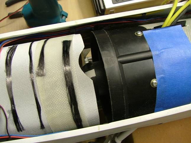
JHI-A7-06-0002

                                      TABLE OF CONTENTS
1.0   INTRODUCTION........................................................................................3
2.0   GENERAL BUILDING TIPS .......................................................................3
3.0   EDF SYSTEM ............................................................................................3
4.0   EDF INSTALLATION .................................................................................4
5.0   AIRCRAFT SETUP AND CG .....................................................................8
6.0   FLYING THE EDF A-7 CORSAIR II ...........................................................8
6.1   Range Check .............................................................................................8
6.2   Power System ............................................................................................8
6.3   First Flight ..................................................................................................8

      Have questions? Call us at 562-467-0260 or email larrywjhi@jethangar.com                                      2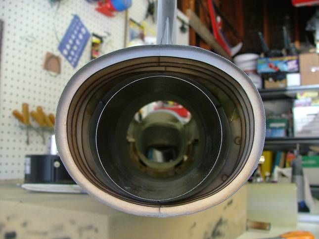
JHI-A7-06-0002

1.0 INTRODUCTION

This addendum documents the procedures for installation of the Electric Turbax
Fan System into the ARF A-7 Corsair II and is supplemental to the instruction
manual JHI-A7-06-0001.

2.0 GENERAL BUILDING TIPS

The ARF A-7 Corsair should be assembled as described by the ducted fan
installations in the instruction manual (ailerons, elevator, rudder, retracts,
etc.) with the exception of the propulsion installation procedure. This
procedure supplements the propulsion system installation making it
specific to the Electric Ducted Fan.

3.0 EDF SYSTEM

The ARF EDF A-7 Corsair II is designed for use with the Jet Hangar International
Electric Turbax Fan System as listed below:

      1    Electric Turbax Ducted Fan System
      1    Neu 1521/1.5Y/ Electric Motor (5mm shaft)
      1    Castle Creations 110HV Electronic Speed Controller
      2    5s1p 5000 mah Lithium Polymer Batteries

       Have questions? Call us at 562-467-0260 or email larrywjhi@jethangar.com          3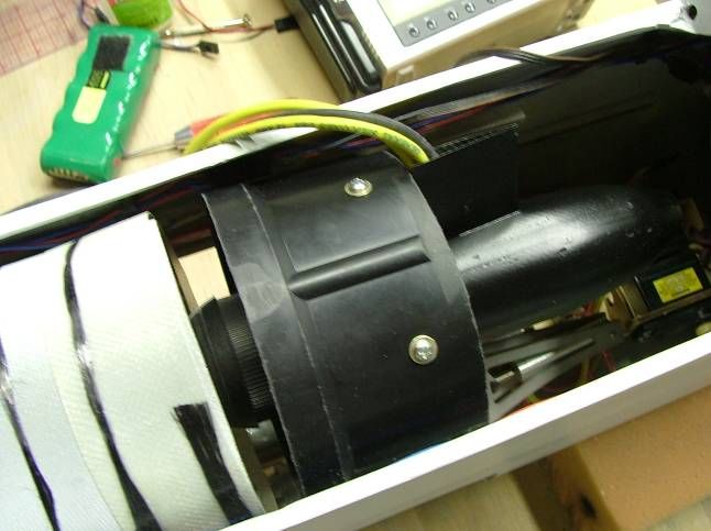
JHI-A7-06-0002
4.0 EDF INSTALLATION
1. Perform the aircraft hardware installations for
Antenna routed into
the control surfaces and retracts per the nose of aircraft
ducted fan instruction manual.
Route all necessary servo/radio extension
leads into the tail of the aircraft. Accessory panel
Install the receiver and receiver battery pack installed per ducted fan
installation
into the tail of the aircraft as shown using
industrial strength Velcro. Note: The
prototype model used a larger 5-cell battery
pack for purposes of balancing the aircraft.
Route the receiver antenna forward into the
nose of the aircraft avoiding wherever
possible any sources of “noise.” These
would be the ESC and battery extension
leads.
2. Assemble the ducted fan unit per the
manufacturer’s instructions. Note: This Fibreglass Slip
aircraft is intended for use with the JHI Ring (SEE STEP
4)
Electric Turbax Fan System.
Trim the aluminum fan mounting rails back
11/32”; drill new mounting holes. This is for
the fan to fit inside the fuselage. Note: Drill
holes into mounting rails only after test fitting
the fan inside the aircraft.
Test fit the ducted fan into the fuselage. Trim
any interference material (including glue
fillets on the wood mounting rails). Set in
Mark Locations
place. Note: The fan shroud is intended to fit
inside of the inlet duct.
Mark and drill the fan mounting holes in the
wood mounting rails installed in the aircraft.
Temporarily mount the fan in place. Note:
The fan should be located such that the fan
shroud is clear of the main wheels in the
retracted position; this may result in the fan
being behind the inlet duct. This is remedied
by step 4.
Before removing the fan for the next steps,
mark the location of the trailing edge of the
aluminum fan mounts and the trailing edge of
the fan shroud.
Have questions? Call us at 562-467-0260 or email larrywjhi@jethangar.com 4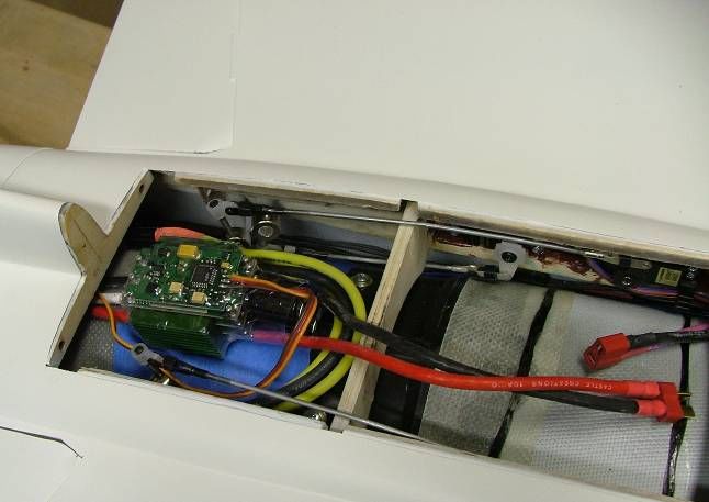
JHI-A7-06-0002
3. Locate the two fiberglass exhaust ducts.
Remove
Note: It is a two piece duct system with the Material
larger diameter mating to the rear of the fan
and tapering down to the smaller diameter at
the aircraft exhaust.
Remove the scale exhaust cone by flexing
the fiberglass and removing the three wire
pins from their tubes.
Test fit the rear exhaust liner into the aircraft
pushing the liner as far back as possible to
achieve a snug fit. Note: Remove
interference material as required at the
trailing edge of the wing saddle to allow duct Cut Slot 3
to slip into place. Places
Trim the exhaust side of the liner to fit in
place as required. The liner should extend
approximately 1-¼” beyond the rear
bulkhead.
Mark the three locations for the scale exhaust
cone attachments. Using a Dremel cutoff
wheel, cut slots at each location in the
direction of the exhaust flow. Note: This is
only required if installing the scale exhaust
cone into the aircraft for static display or
flight.
4. Locate the supplied fiberglass sheet and trim
to approximately 1 ¾”-2” in width by 17 ¼”
long.
Wrap the fiberglass sheet around the outside
of the front of the fan shroud and mark the
crossover location. Cut the fiberglass at the
mark. The excess ¾” strip is used to seam
the fiberglass ring in the next step.
CA the ¾” strip to the rough side (one side Opening for
only) of the 2” fiberglass sheet. Spinner
Wrap the fiberglass sheet around the fan
shroud and glue the ¾” strip to the other half
side of the fiberglass sheet creating a ¾” Seam
Strip
fiberglass ring.
Create a slight opening on the trailing edge of
the inlet duct. Note: This is to allow for the
fan spinner to pass through for ease of
installation and removal of the fan.
Install the fiberglass ring over the inlet duct
sliding it back to allow the spinner to pass
through the opening created.
Have questions? Call us at 562-467-0260 or email larrywjhi@jethangar.com 5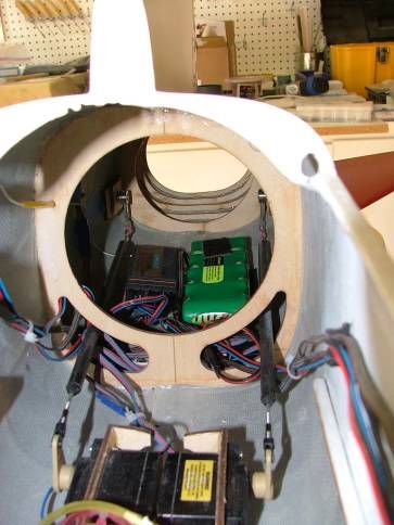
JHI-A7-06-0002
5. With the rear exhaust liner in place, test fit
the front exhaust liner in the aircraft. Note:
The rear of the front exhaust liner has a
beveled edge. The top of the liner should
orient the bevel angle with the longest side at
top, shortest at bottom of aircraft.
While in the aircraft, note the location of the
fan mounting rails and trim the exhaust liner
to fit. Note: It is best to split the difference
from the front and rear of the exhaust liner.
For example, the prototype model required
that about 1” be trimmed, ½” was trimmed
from either end.
Carefully cut a tapered slot into the fan
interfacing exhaust duct to allow for the
hollow stator extension on the fan tailcone.
Note: The motor wires are routed through the
stator extension on the tailcone.
Slip the front exhaust liner onto the rear of
the fan shroud and tape in place on the top
and bottom of the fan.
6. Test fit the fan/liner assembly into the aircraft
and slide the slip ring in place over the fan
shroud.
Slip Ring
Note the location of the main wheels in the
retracted position on the inlet and slip ring.
Cut openings in the inlet liner and slip ring to
allow for the main wheels to fully retract.
Note: Openings should be just enough to
allow for the wheels to retract into place.
Minimize as much as possible any “over
cutting.”
Install the fan/liner assembly into the aircraft.
Slide the fiberglass slip ring forward over the
fan shroud so that there is approximately ½”
of fiberglass overlapping the fan shroud.
Note: For final installation of the fan unit, tack
gluing the slip ring to the inlet duct is
recommended to add rigidity and hold it in
place. Tack glue only as the ring must be
able to be popped free to remove the fan.
Install the speed controller into the airplane
as shown.
Have questions? Call us at 562-467-0260 or email larrywjhi@jethangar.com 6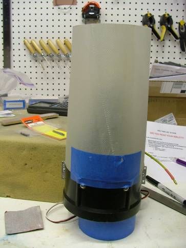
JHI-A7-06-0002
7. Test fit the two 5s batteries into the nose of
the aircraft. Note: The batteries are intended
to fit on top of the inlet into the turtle deck
between the cockpit and leading edge of the
wing saddle.
Check the cg of the aircraft per the instruction
manual JHI-A7-06-0001. If necessary,
relocate components to achieve cg.
Create a series connector as shown in figure
1. The 2 5s batteries are to be wired in
series to create a single 10s1p battery pack.
Install the series connector into the aircraft.
To ESC
+ -
+ -
Deans
Connectors
+ -
+ - +
-
- +
+ - + -
5s 5s
Battery Battery
Figure 1: Battery Connection Schematic
Have questions? Call us at 562-467-0260 or email larrywjhi@jethangar.com 7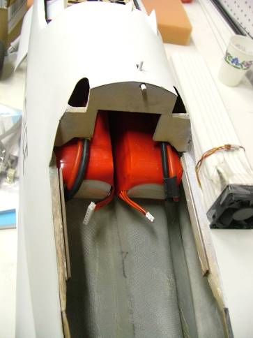
JHI-A7-06-0002
5.0 AIRCRAFT SETUP AND CG
Once all aspects of the assembly have been finished, ensure the aircraft is setup
and balanced as noted in instruction manual JHI-A7-06-0001. Note these are
recommended start values for the first flights. These can be tailored to suit
personal preferences as desired once the initial flights have been completed.
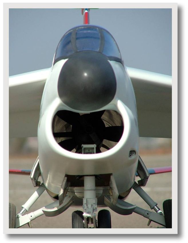
6.0 FLYING THE EDF A-7 CORSAIR II
The EDF ARF A-7 Corsair II is a high performance R/C electric jet aircraft. It has
been designed for scale accuracy and flight performance. The aircraft flies like a
high performance trainer as it is extremely stable in all axes of flight. Capable of
high speeds upwards of 140-160 mph with the E-turbax fan, the aircraft also
retains excellent slow speed handling. The high lift provided by the A-7’s fixed
droop leading edge, coupled with trailing edge flaps, allows for very positive
control at incredibly slow flight speeds. The aircraft possesses a long glide,
making it very docile to land while the high lift wing requires only moderate take-
off speeds to become airborne. Target weight with EDF is 12.5-13 lbs.
6.1 Range Check
Perform the range check with the antenna down and with the propulsion system
off and also running. If unable to achieve a good range check or if any glitching
is noted, rerouting of the receiver antenna and relocation of some of the
electronics may be required.
6.2 Power System
Check the power levels of the propulsion system installed in the aircraft. The
recommended Electric Turbax setup will run approximately 87 amps and 3100
watts using a 20c 5000 mah 10s1p lithium battery. This setup is good for
approximately a 4-1/2 minute flight depending on throttle usage. Note that if one
were to fly full throttle for the duration of the batteries and able to achieve a
continuous 87 amp current draw (current draw does decrease over time), this
equates to 3.4 minutes of run time on the system. Additionally, for best results
and longevity of the batteries, it is best to use up to 90% of the battery charge in
a flight as fully discharging the batteries can result in cell imbalances and
damage the battery packs.
6.3 First Flight
When accelerating the aircraft down the runway for takeoff, carry a very slight
amount of up elevator during the ground roll. The reason is two fold: first, it will
desensitize the nose wheel steering and, secondly, it will maintain positive
attitude on the ground roll. Note that the EDF A-7 will accelerate very rapidly on
the takeoff at full throttle and is able to get airborne from pavement in about 100
Have questions? Call us at 562-467-0260 or email larrywjhi@jethangar.com 8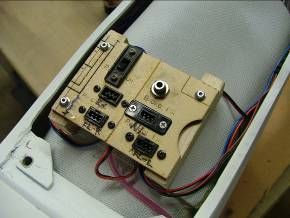
JHI-A7-06-0002

feet. Once in the air, get a feel for the control of the aircraft prior to exercising
any maneuvers. Additionally, spend a good portion of the flight at partial throttle
to maximize the flight time. Perform some slow flight and check how the aircraft
responds to the different flap settings before attempting to land with flaps. With
the correct amount of flap/elevator mixing, the aircraft should not change trim
with flap deflections. Lastly, it is recommended the first flight be limited to 3-
3.5 minutes using full throttle for takeoff and a select few passes only.
Recharging the batteries will show the amount of capacity used during the flight
which can be used to gauge the time for the next flight. The average current
draw for the flight can be determined by dividing the amount of capacity used (in
amp hours) by the flight time (in hours). In general, full throttle should be used
for high speed passes and maneuvers while throttling back on the downwind.

This is a very easy flying aircraft which we hope you will enjoy! If we can help in
any way, please do not hesitate to contact us.

       Have questions? Call us at 562-467-0260 or email larrywjhi@jethangar.com          9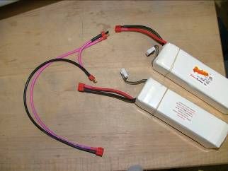
You can also read