Study of Flow Structure and its effect on Indian Train Using C.F.D. Technique
←
→
Page content transcription
If your browser does not render page correctly, please read the page content below
International Journal of Advanced Mechanical Engineering.
ISSN 2250-3234 Volume 4, Number 5 (2014), pp. 463-468
© Research India Publications
http://www.ripublication.com

Study of Flow Structure and its effect on Indian Train Using
                    C.F.D. Technique

                    Vivek Kumar and Abhishek Pratap Singh

          Student, B.Tech. Mechanical, ITM University, Gurgaon, Haryana
           Deptt of Mechanical Engg., ITM University, Gurgaon, Haryana

                                      Abstract

   Present research aims to Study of the Flow Structure and its effect on Indian
   Trains using C.F.D. Technique. The purpose of the study was to simulate and
   analyze the flow structure and finding the high pressure points and suggesting
   suitable changes to eliminate them by low pressure points and study the
   velocity pattern of air across the body. This analysis is done on 2-D Structure
   of the concerned object. Objective of this research is to study the air flow over
   the Indian Railways and to find out the high pressure points created due to the
   motion of the vehicle. In order to achieve the desired result, C.F.D technique
   is used and software on which project work is carried out is ANSYS Fluent.
   Results show that the current design of the locomotive and the bogie has
   certain flaws. If these flaws are removed, design of the vehicle will be more
   attractive in looking, it will be more aerodynamically stable and speed and
   efficiency of the system will also get increased. Centre of the gravity of the
   vehicle will also be lowered as the ground clearance can be reduced. Current
   design faces unwanted amount of drag force and more material consumption
   in manufacturing. High pressure points are generated on the front of the
   locomotive and the engine has to do extra work to overcome the drag so
   created by these points.

   Keywords: Indian Train, Locomotives, Bogies, Air, Fluid flow, C.F.D.,
   ANSYS, Fluent.

Introduction
Certain Problems which are identified when we compare Indian Railways with the
railways of some other countries. In India, average number of wagons are around 23
for long distance travel whereas in countries like Australia number goes up to 48. The
fastest train in India is Bhopal Shatabdi between New Delhi – Bhopal Junction with a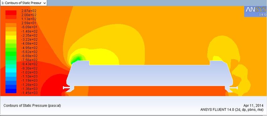
464                                         Vivek Kumar and Abhishek Pratap Singh

maximum speed of 161 km/h (100 mph) and an average speed of 87.17 km/h (56.5
mph), excluding stops. In India, design of the engine is “old school” i.e. No new
development is made in a long time, only old designs are modified a bit, but no new
concepts are made whereas in other countries proper R&D departments are there for
research work. Indian trains face max, air drag force as compared to engines of trains
in other countries because of their old design. Indian railways also lag in terms of
aerodynamics and air flow analysis. Present Study has been done to understand the
concepts of fluid dynamics and its application, and to study, the airflow over the
Indian Railways, behavior of air at different locations, and aerodynamic concepts
involved. The study identified the various high pressure points created due to the
motion of the vehicle, velocity variation of air when it comes in contact with the
vehicle. Present study suggested changes in the design and shape of the engine for
better working and efficiency, improvement of the shape and design of the engine,
improvement in the looks of the train, and, proper air flow over the engine, hence less
effect of air drag force, and more speed of train for the same amount of fuel.

Geometrical Model Setup:
The ultimate purpose of a finite element analysis is to recreate mathematically the
behavior of an actual engineering system. In other words, the analysis must be an
accurate mathematical model of a physical prototype. In the broadcast sense, this
model comprises all the nodes, elements, material properties, real constants, boundary
conditions, and other features that are used to represent the physical system. The
object here is referred to the Indian Railways Locomotive and the bogies. There
dimensions and figured is drawn on the basis of the information obtained from the
Internet and the official website of Indian Railways. Some of the illustrations which
displays the dimensions are given in Figure 1. The process for generating a mesh of
nodes and elements consists of three general steps (i) Set the element attributes, (ii)
Set mesh controls. ANSYS offers a large number of mesh controls from which we can
choose as needs dictate. (iii) Meshing the model.

                       Figure 1. Dimension of the locomotive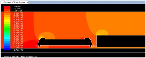
Study of Flow Structure and its effect on Indian Train Using C.F.D. Technique 465
Experimental Setup:
The discretized conservation equations are solved iteratively until convergence.
Pressure based solver is applicable for a wide range of flow regimes from low speed
incompressible flow to high speed compressible flow. We define the input velocity in
Absolute Reference Frame and its value in X-direction is 20m/s. Turbulence intensity
is set to 1% and turbulent viscosity ratio to 10. In similar fashion, we determine the
pressure outlet parameter. Make sure that symmetry parameter has symmetry type
selected and the wall parameter has the wall type selected. Next we make sure that the
reference values are computed from the inlet.
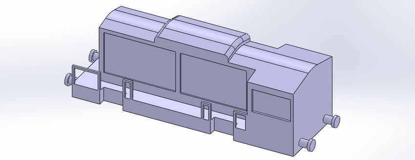
Figure 2. 3-D graphical Model of a Locomotive
Result Discussion
As the flow analysis results are obtained for the single locomotive in motion, it is
observed that High Pressure points are developed at the front side of locomotive and
under the locomotive. When it comes in term of the velocity, it appears that velocity
of air films which are in contact with the locomotive don’t vary much. But change in
velocity is observed above the locomotive. Low velocity zone is obtained right behind
the locomotive which exists till certain distance. Maximum velocity contour is
obtained at the front top of the locomotive. The same behavior is depicted by the
velocity vectors. Fair amount of velocity contour is obtained below the locomotive.
Turbulence is produced over the top of the locomotive and bottom end of the
locomotive. As compared to normal velocity of nearby air, turbulence produced is not
much in magnitude.466 Vivek Kumar and Abhishek Pratap Singh
Figure 3. Contours of static pressure on a 2-D locomotive
As the flow analysis results are obtained for the single locomotive and single
bogie arrangement, we observed that High Pressure region is formed at the bottom
half of the front of the locomotive and a little bit less pressure region is formed at the
bottom of the locomotive. On the top of the locomotive, there exists a high pressure
region whose magnitude is little less than what’s developed at the front of the
locomotive. Normal pressure zone is formed above the bogie. After a little back from
the bogie, pressure zone starts to become normal again. Turbulence is formed at the
top as well as the bottom of the locomotive and large section at the back of the bogie.
As compared to surrounding air, its magnitude is not that much. Slight turbulence is
also observed at the top of the bogie. Majorly, the High Velocity regions are formed
above the locomotive and the bogie. Low velocity regions exist for the air layers
which are in contact with body. Low velocity region also exist in the gap between the
locomotive and the bogie. Partial low velocity regions are obtained behind the bogie.
Velocity region formed below the bogie is more than that is formed below the
locomotive.
Figure 4. Contours of static pressure on a locomotive and a bogieStudy of Flow Structure and its effect on Indian Train Using C.F.D. Technique 467
As the flow analysis results are obtained for one locomotive and four bogies
arrangement, we observed that High Pressure region is formed at the bottom half of
the front of the locomotive and at the bottom of the locomotive. A little less pressure
region is formed at the top of the locomotive. Around the bogies pressure region is
almost same i.e. medium pressure region. Medium pressure regions are also formed
behind the bogies. Turbulence is obtained at the top of the locomotive and the top of
the first locomotive. A large turbulence region is obtained at the back of the bogies. A
fairly good velocity region is observed above the locomotive and the bogies. This
region exists till a little distance beyond the last bogie. Very low velocity regions are
observed between the locomotive and bogie as well as between the bogies. Small
packets of low velocity regions are formed behind the last bogie.
Figure 5. Contours of static pressure on front of a locomotive
Conclusion
It can be suggested that some changes in the design and structure of the locomotive
and the bogies which can improve the various things like the speed, aerodynamics,
engine efficiency. Changes the shape of the locomotive and make it more pointed out
in the front and increase the slope of the front surface then airflow patter will change.
Air will flow over the surface to the sideways and resulting in less air drag. It
increases the speed of the locomotive and makes the design more aerodynamically
stable. Some pressure zone and velocity variations are observed below the
locomotive. If we decrease the ground clearance up to some suitable extent then such
points can be reduced for good. There are some low velocity regions between the
bogies. We can make the bogies in the continuous formation which has same height
and cross section throughout the length. In this way a uniform space will be available
for continuous airflow.
The present study is aimed at enhancing our understanding of the stated problem
and technical capabilities involved in finding a workable solution for the same. In468 Vivek Kumar and Abhishek Pratap Singh
addition, an attempt can be made to find out the extent of application of CFD code
FLUENT in the air flow analysis on Indian Railway Locomotive. Further effect of
wind orientations, varying aspect ratios, varying locomotive geometries as well
varying environmental conditions could be analyzed in the future for more responsive
solutions. An attempt could also be made for analyzing Indian Train as a whole i.e.
Locomotive and Bogies systematically attached like in real life condition.
References
[1] Tim Langlais, Ansys Short Course lecture (langlais@me.um.edu), on August
16, 1999.
[2] Dr. Mohammad O. Hamdan, lecture on Ansys Fluent in Spring 2010.
[3] ©Ansys Fluent Theory by Ansys Inc.
[4] Rajesh Bhaskaran, Lecture notes on Introduction to CFD Basics
[5] Andre Bakker, Applied Computational Fluid Dynamics,
http://www.bakker.org, ©Bakker(2002-2006).
[6] Elizabeth M. Marshall and Andre Bakker, Fluent Inc., Technical Notes on
Computational Fluid Mixing, submitted to the North American Mixing Forum
(NAMF) Handbook on Mixing January,2001.
[7] Tao Xing and Fred Stern, Simulation of Turbulent Flow over Ahmed Body,
Intermediate Mechanics of Solid, CFD Lab, By:, IIHR- Hydroscience and
Engineering, The University of Iowa, C. Maxwell Stanley Hydraulics
Laboratory, Iowa City, IA 52242-1585.
[8] Tennekes H., Lumley J.L. “A First Course in Turbulence .” The MIT Press
1972.
[9] Versteeg H.K., Malalasekera W. (1995) “An Introduction to Computational
Fluid Dynamics: The Finite Volume Method” by Longman Scientific &
Technical. ISBN: 0-582-21844-5.
[10] Pope, Stephen B. “Turbulent Flows.” Cambridge University Press 2000.You can also read