Toyota Supra MKIII Installation Manual - Firmware Version 3.1
←
→
Page content transcription
If your browser does not render page correctly, please read the page content below
Toyota Supra MKIII Installation Manual – Firmware Version 3.1
Warnings:
Before proceeding you are obligated to read and agree to the terms and conditions attached to this manual.
Misuse of this product may cause injury or death.
Incorrect installation may cause damage to your vehicle and may void the warranty.
Tools Required:
Wire cutter / crimper
Soldering iron / solder
12 volt momentary buttons (optional)
SPST switch (optional)
voltmeter
Installation
For questions or technical support, email tech@latentsolutions.com
1. Remove the passenger’s side kick panel, glove box, and inner glove box cover.
The car’s engine ECU is located on the upper left of the glove box opening.
The ECT ECU is located behind the passenger’s right lower kick panel.
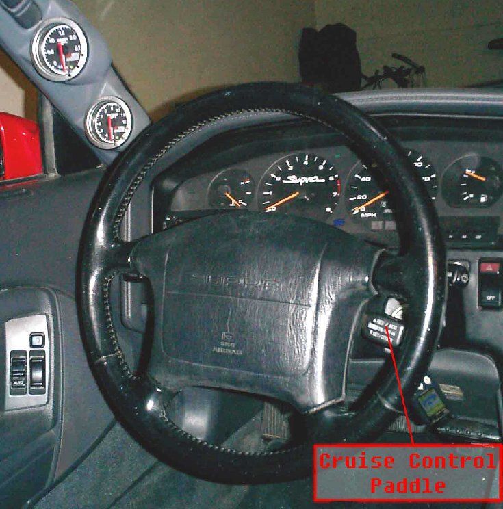
The Cruise Control ECU (89+) is above the driver’s lower kick panel, by the steering column2.
Wiring Diagram: All connections should be spliced except Sol 1, Sol 2, and Sol L which require the 3 wires to be cut.
Wire Color Number Description
Black 1 Ground
White 2 Manual / Auto Selector (12 volts = man, 0 volts = auto)
Red 3 Ignition +
Light Blue 4 Sol 1 (ECT ECU Side of cut wire)
Tan 5 Sol 2 (ECT ECU Side of cut wire)
Yellow 6 Sol L (ECT ECU Side of cut wire)
Orange 7 Upshift (12 volts = shift)
Light Green 8 Downshift (12 volts = shift)
Dark Green 9 Throttle Position (TPS signal wire)
Brown 10 Cruise Control Paddle
White/Brown 11 RPM (NE signal wire)
White/Blue 12 Brake Signal
Pink 13 Sol 1 (Tranny Side of cut wire)
Gray 14 Sol 2 (Tranny Side of cut wire)
Dark Blue 15 Sol L (Tranny Side of cut wire)
Purple Unit Test Signal / Shift LightTips:
Stealth Install:
Use the cruise control paddle from the 89+ supra as a built in
paddle shifter. Stock cruise control operation is retained when the
Suprastick is in the “Fully Automatic” mode.
Use the stock ECT PWR button to switch between manual and
automatic modes of the Suprastick.
(Follow the provided wiring diagram above for the stealth install)
The white Manual / Auto selector lead may be wired to the #2 in the wiring diagram and use the
ECT switch next to the gear shifter for mode selection, or any 12 volt switch and source.
The cruise control paddle wire is located under the driver’s side dash. It is the pink /
green wire in the wire loom coming from the steering wheel and connecting to the cruise control
ECU. It will shift voltages when the paddle is pressed up or down, and be constant 12 volts
when the paddle is not touched.
3. Initial Tests
After connecting all of the SupraStick wires, but before replacing the kick panels and
glove box, start by turning the car’s ignition to on (do not start the car). The SupraStick unit will
click twice. Select manual shifting mode. Shift up and down through the gears. You should
hear a distinctive click in the SupraStick box and in the tranny for each shift. You may verify the
following voltages on wires 13-15 for each gear.
Gear Wire Gear Wire Gear Wire Gear Wire
Voltage Voltage Voltage Voltage
1 d.blue 0 2 d.blue 0 3 d.blue 0 4 d.blue 0
gray 0 gray 12 gray 12 gray 0
pink 12 pink 12 pink 0 pink 0
Start the car, and put SupraStick into the normal automatic mode. Connect a test light or
a voltmeter between the Unit Test Signal Wire and +12 volts. You will see continuity when any
of the following conditions are true:
Upshift Signaled
Downshift Signaled
Brake Applied
Throttle > 5%
RPM between 1100 and 1400 rpm
Once you have completed the tests to your satisfaction and reinstalled the kick panels and glove
box the instillation is complete.Programming
The unit is programmable to suit your car’s transmission and your own personal
preferences. Enter the programming mode by pressing the Manual / Auto Selector 5 times
within 5 seconds, ending with the manual mode on. The unit will flash the Unit Test Signal 3
times.
The following diagram describes how to program the unit. The program mode starts in
the upper left corner. Downshift to move down one row, Upshift to move over a column. The
Unit Test Signal will flash long flashes to indicate a new row selected, and short flashes to
indicate a new column selected. Once you hit the end of a row or column, the next row or
column signal will automatically loop back to the beginning of that respective row or column.
Example: To program a rev limit +300, stall speed 3000, lockup delay disabled, and the shift
light of 5500 rpm, enter the programming mode – the unit flashes 3 times in acknowledgement.
Upshift once, the unit flashes 2 quick flashes. Downshift, the unit flashes 2 long flashes.
Downshift, the unit flashes 3 long flashes. Upshift, the unit will flash quickly twice, Upshift, the
unit will flash quickly 3 times, and Upshift, the unit will flash quickly 4 times. Downshift, the
unit flashes 4 long flashes. You must wait for the flashes before shifting again. Finally
deselect the manual shifting mode to save the settings.
Upshift
Downshift
Normal Downshift Rev Downshift Rev Downshift Rev
Downshift Limit Limit Limit
Rev Limit +300 RPM +600 RPM +900 RPM
(default)
Stall Speed Stall Speed Stall Speed Stall Speed
2500 3000 3500 4000
(default)
Lockup Delay Lockup Delay
Lockup Delay Lockup Delay Disabled
Normal +400 ms +800 ms (if locked, will not unlock
(default)
during shifts)
Shift Light Shift Light Shift Light Shift Light
5500 rpm 5800 rpm 6100 rpm 6400 rpm
(default)Operation
The system operates in two modes: Normal Automatic Mode and Manual Shifting Mode.
You may switch between the modes at any time. Normal Auto mode operates identically to the
stock system. No user intervention is required. Selecting Manual Shifting Mode places the
driver in full control of all shifts – any shift the car makes will be in direct response to an up or
downshift you command.
Use extreme care, especially in low gears, not to over rev the transmission. You
are responsible for shifting in manual shifting mode.
The system will prevent accidental downshifts at an rpm that will redline the engine upon
downshifting.
Use extreme care downshifting at high rpm. The system is designed to the limits
of the car and an experienced driver
Tech Tips & F.A.Q.
In Manual mode, SupraStick employs an aggressive lockup scheme in all 4 gears to
improve shifting speed and deliver more power to the wheels. In first and second gears, with at
least 30% throttle the system will be eligible for lockup, depending on engine rpm, throttle
position, and stall speed setting.
You can delay lockup while shifting gears to help control wheel spin or traction loss by
not releasing the shift button or lever upon shifting. The system will wait for release before
enabling lockup computation or allowing another shift.
Stall Speed – this option in the programming mode affects the rpm at which the torque
converter locks up. The actual rpm at which lockup begins and ends is based on the stall speed
setting, current gear, and throttle position.
Suprastick uses the brake signal input to disable torque converter lockup while the brakes
are applied.
Lockup delay sets the “wait time” between shifts before the torque converter is allowed
to lock up again. The default setting is the quickest setting that still unlocks the torque converter
between shifts. Setting the lockup delay to “disabled” keeps the torque converter locked up
during the shift sequence, as long as all torque converter perquisites are maintained. This is
recommended as a “race only” mode as it will put much more stress on the transmission.
The system will fail to operate if the RPM wire is not connected. If downshift rev
protection is not desired (not recommended) connect this wire to ground to bypass RPM
checking.
The rpm at which downshift is disabled at varies by gear. With the default setting the 4-3
limit is 4000 rpm, the 3-2 limit is 3600 rpm, and the 2-1 limit is 2900 rpm.
The unit test / shift light wire will output +12 volts when above the rpm set in the user
options.PLEASE READ THESE WARRANTIES AND DISCLAIMERS CAREFULLY BEFORE INSTALLING AND USING THE SUPRASTICK. BY PURCHASING THE SUPRASTICK, YOU INDICATE YOUR AGREEMENT TO THESE WARRANTIES AND DISCLAIMERS. IF YOU ARE NOT AGREEABLE TO THESE WARRANTIES AND DISCLAIMERS, DO NOT INSTALL OR USE THE SUPRASTICK. Limited Warranty Latent Solutions warrants this product to be free from manufacturing defects in its original parts and workmanship under normal use and conditions (“manufacturing defect”) for a period of six (6) months from date of original purchase (“warranty”). THIS WARRANTY IS NON-TRANSFERABLE AND APPLIES ONLY TO THE ORIGINAL PURCHASER AND DOES NOT EXTEND TO SUBSEQUENT OWNERS OF THE PRODUCT. ANY APPLICABLE IMPLIED WARRANTIES, INCLUDING THE WARRANTY OF MERCHANTABILITY, ARE LIMITED IN DURATION TO A PERIOD OF THE EXPRESSED WARRANTY AS PROVIDED HEREIN BEGINNING WITH THE DATE OF ORIGINAL PURCHASE AT RETAIL AND NO WARRANTIES, WHETHER EXPRESSED OR IMPLIED, SHALL APPLY TO THE PRODUCT THEREAFTER. Disclaimers of Warranties LATENT SOLUTIONS MAKES NO WARRANTY AS TO THE FITNESS OF THE PRODUCT FOR ANY PARTICULAR PURPOSE OR USE. Latent Solutions makes no warranty, representation or guaranty as to the SupraStick’s performance or legality in some jurisdictions. Latent Solutions makes no warranty, representation or guaranty that (i) the information and directions provided in the Installation Manual will be followed to their fullest extent, (ii) that the installation of SupraStick will not void any warranties that an automobile, its’ parts or equipment are currently covered under, (iii) the installation of SupraStick will be executed by persons with the mechanical and technical ability to perform the task or (iv) that any defects with the installation or performance of the SupraStick can be corrected. For the purpose of these disclaimers and the limitation of liability described below Latent Solutions includes its divisions, subsidiaries, successors, parent companies, and their respective employees, partners, principals, agents, technicians, mechanics, representatives and third-party providers and sources of information and data. SOME JURISDICTIONS MAY NOT ALLOW THE EXCLUSION OF IMPLIED WARRANTIES, SO THE ABOVE EXCLUSIONS SHALL ONLY APPLY TO THE EXTENT PERMISSIBLE UNDER APPLICABLE LAW. Limitation of Liability Under no circumstances shall Latent Solutions be liable for any losses or damages whatsoever, including but not limited to any indirect, special, incidental or consequential damages arising from the installation of, or the use of, the SupraStick, including but not limited to damages to an automobile or any if its parts or equipment or use. SOME JURISDICTIONS MAY NOT ALLOW THE EXCLUSION OR LIMITATION OF INCIDENTAL OR CONSEQUENTIAL DAMAGES, SO THE ABOVE EXCLUSIONS SHALL ONLY APPLY TO THE EXTENT PERMISSIBLE UNDER APPLICABLE LAW. As to the Installation Manual: WARNING: READ AND UNDERSTAND ALL INSTRUCTIONS BEFORE INSTALLING THE SUPRATICK. WARNING: THE SUPRASTICK MAY NOT COMPLY WITH SOME JURISDICTION’S LAWS. PLEASE CHECK ALL APPLICABLE LAWS BEFORE INSTALLING OR USING THE SUPRASTICK TO ENSURE THAT YOU ARE IN COMPLIANCE WITH THE LAWS. LATENT SOLUTIONS WILL NOT BE HELD RESPONSIBLE FOR THOSE INDIVIDUALS WHO DO NOT FOLLOW THE APPLICABLE LAWS AS TO THE INSTALLATION AND USE OF THE SUPRASTICK.
You can also read