Consolidated 3500-1/2/3 EBV Series - Electromatic Ball Valve System Instruction Manual (Rev. D) - Baker Hughes ...
←
→
Page content transcription
If your browser does not render page correctly, please read the page content below
Consolidated                                ™

3500-1/2/3 EBV Series
Electromatic™ Ball Valve System

Instruction Manual (Rev. D)

Baker Hughes Data Classification : Public
THESE INSTRUCTIONS PROVIDE THE CUSTOMER/OPERATOR WITH IMPORTANT
  PROJECT-SPECIFIC REFERENCE INFORMATION IN ADDITION TO THE CUSTOMER/
  OPERATOR’S NORMAL OPERATION AND MAINTENANCE PROCEDURES. SINCE
  OPERATION AND MAINTENANCE PHILOSOPHIES VARY, BAKER HUGHES (AND
  ITS SUBSIDIARIES AND AFFILIATES) DOES NOT ATTEMPT TO DICTATE SPECIFIC
  PROCEDURES, BUT TO PROVIDE BASIC LIMITATIONS AND REQUIREMENTS
  CREATED BY THE TYPE OF EQUIPMENT PROVIDED.
  THESE INSTRUCTIONS ASSUME THAT OPERATORS ALREADY HAVE A GENERAL
  UNDERSTANDING OF THE REQUIREMENTS FOR SAFE OPERATION OF MECHANICAL
  AND ELECTRICAL EQUIPMENT IN POTENTIALLY HAZARDOUS ENVIRONMENTS.
  THEREFORE, THESE INSTRUCTIONS SHOULD BE INTERPRETED AND APPLIED
  IN CONJUNCTION WITH THE SAFETY RULES AND REGULATIONS APPLICABLE AT
  THE SITE AND THE PARTICULAR REQUIREMENTS FOR OPERATION OF OTHER
  EQUIPMENT AT THE SITE.
  THESE INSTRUCTIONS DO NOT PURPORT TO COVER ALL DETAILS OR VARIATIONS
  IN EQUIPMENT NOR TO PROVIDE FOR EVERY POSSIBLE CONTINGENCY TO BE MET
  IN CONNECTION WITH INSTALLATION, OPERATION OR MAINTENANCE. SHOULD
  FURTHER INFORMATION BE DESIRED OR SHOULD PARTICULAR PROBLEMS ARISE
  WHICH ARE NOT COVERED SUFFICIENTLY FOR THE CUSTOMER/OPERATOR'S
  PURPOSES THE MATTER SHOULD BE REFERRED TO BAKER HUGHES.
  THE RIGHTS, OBLIGATIONS AND LIABILITIES OF BAKER HUGHES AND THE
  CUSTOMER/OPERATOR ARE STRICTLY LIMITED TO THOSE EXPRESSLY PROVIDED
  IN THE CONTRACT RELATING TO THE SUPPLY OF THE EQUIPMENT. NO ADDITIONAL
  REPRESENTATIONS OR WARRANTIES BY BAKER HUGHES REGARDING THE
  EQUIPMENT OR ITS USE ARE GIVEN OR IMPLIED BY THE ISSUE OF THESE
  INSTRUCTIONS.
  THESE INSTRUCTIONS ARE FURNISHED TO THE CUSTOMER/OPERATOR SOLELY
  TO ASSIST IN THE INSTALLATION, TESTING, OPERATION, AND/OR MAINTENANCE
  OF THE EQUIPMENT DESCRIBED. THIS DOCUMENT SHALL NOT BE REPRODUCED
  IN WHOLE OR IN PART WITHOUT THE WRITTEN APPROVAL OF BAKER HUGHES.

ii | Baker Hughes                                  © 2020 Baker Hughes Company. All rights reserved.
Conversion Table
          All the United States Customary System (USCS) values are
          converted to metric values using the following conversion
                                    factors:

                    USCS Unit                              Conversion Factor                            Metric Unit

                           in.                                       25.4                                     mm

                           lb.                                   0.4535924                                     kg

                           in2                                     6.4516                                     cm2

                        ft3/min                                 0.02831685                                  m3/min

                       gal/min                                    3.785412                                   L/min

                         lb/hr                                   0.4535924                                   kg/hr

                         psig                                   0.06894757                                   barg

                          ft lb                                  1.3558181                                    Nm

                           °F                                    5/9 (°F-32)                                   °C

     Note: Multiply USCS value with conversion factor to get metric value.

                                                                    NOTICE!
                                                    For any service questions not covered
                                                    in this manual, please contact your local
                                                    Green Tag™ Center (GTC).

© 2020 Baker Hughes Company. All rights reserved.                                       Consolidated 3500-1/2/3 EBV Series POSRV Manual | iii
Table of Contents
I. Product Safety Sign and Label System ������������������������������������������������������������������������������������������������������1
II. Safety Precautions��������������������������������������������������������������������������������������������������������������������������������������2
III. Safety Notice�����������������������������������������������������������������������������������������������������������������������������������������������5
IV. Warranty Information�����������������������������������������������������������������������������������������������������������������������������������6
V. Valve Terminology���������������������������������������������������������������������������������������������������������������������������������������7
VI. Handling and Storage����������������������������������������������������������������������������������������������������������������������������������9
VII. Design Features and Nomenclature����������������������������������������������������������������������������������������������������������10
VIII. Introduction������������������������������������������������������������������������������������������������������������������������������������������������10
IX. Consolidated 3500 Series Safety Valves��������������������������������������������������������������������������������������������������� 11
X. Operating Principles����������������������������������������������������������������������������������������������������������������������������������15
XI. Recommended Installation Practices��������������������������������������������������������������������������������������������������������18
A. Main Valve��������������������������������������������������������������������������������������������������������������������������������������������18
B. Type 3539 Controller ���������������������������������������������������������������������������������������������������������������������������18
C. Required Wire Gauge �������������������������������������������������������������������������������������������������������������������������18
D. Cable - Special Conditions Use�����������������������������������������������������������������������������������������������������������19
E. Limit Switch Enclosure - Special Conditions Use��������������������������������������������������������������������������������19
F. ASCO Solenoid - Special Conditions Use�������������������������������������������������������������������������������������������19
XII. Disassembly of 3500 Series Safety Valve�������������������������������������������������������������������������������������������������20
A. Ball, Seat and Loader Assembly Removal�������������������������������������������������������������������������������������������20
B. Actuator Assembly Removal����������������������������������������������������������������������������������������������������������������20
C. Stem Removal ������������������������������������������������������������������������������������������������������������������������������������21
D. Cleaning�����������������������������������������������������������������������������������������������������������������������������������������������21
XIII. Maintenance Instructions��������������������������������������������������������������������������������������������������������������������������22
A. Seat Leakage���������������������������������������������������������������������������������������������������������������������������������������22
B. Packing Leakage ��������������������������������������������������������������������������������������������������������������������������������22
C. Electrical System ������������������������������������������������������������������������������������������������������������������������������� 23
XIV. Inspection and Part Replacement�������������������������������������������������������������������������������������������������������������36
XV. Reassembly of 3500 Series Safety Valve��������������������������������������������������������������������������������������������������36
A. Lubrication ������������������������������������������������������������������������������������������������������������������������������������������36
B. Tools Required ������������������������������������������������������������������������������������������������������������������������������������36
C. Valve Assembly �����������������������������������������������������������������������������������������������������������������������������������36
D. Actuator and Accessory Assembly for LEDEEN GS and SY Series Actuators����������������������������������� 38
E. Actuator and Accessory Assembly for LEDEEN Models VA123 Actuators������������������������������������������ 40
XVI. Setting and Testing������������������������������������������������������������������������������������������������������������������������������������42
A. Start-Up of the System�������������������������������������������������������������������������������������������������������������������������42
1. Prior to Start Up Checks ��������������������������������������������������������������������������������������������������������������42
2. System Start Up ���������������������������������������������������������������������������������������������������������������������������42
3. Adjusting the Set Pressure and Blowdown ����������������������������������������������������������������������������������42
4. Minimum Blowdown Setting ���������������������������������������������������������������������������������������������������������44
B. Hydrostatic Testing�������������������������������������������������������������������������������������������������������������������������������44
iv | Baker Hughes © 2020 Baker Hughes Company. All rights reserved.C. MVC-5000 --Start-Up of the System����������������������������������������������������������������������������������������������������45
1. Prior to Start-Up Checks���������������������������������������������������������������������������������������������������������������45
2. Setting of the EBV and Digital Controller��������������������������������������������������������������������������������������46
3. System Start-Up����������������������������������������������������������������������������������������������������������������������������47
4. Adjusting the Set Pressure and Blowdown�����������������������������������������������������������������������������������47
5. Minimum Blowdown Setting����������������������������������������������������������������������������������������������������������47
6. Hydrostatic Testing������������������������������������������������������������������������������������������������������������������������47
XVII. Troubleshooting�����������������������������������������������������������������������������������������������������������������������������������������48
XVIII. Maintenance Tools�������������������������������������������������������������������������������������������������������������������������������������50
A Disassembly and Reassembly Required Tools������������������������������������������������������������������������������������50
XIX. Replacement Parts Planning���������������������������������������������������������������������������������������������������������������������52
A. General Information ����������������������������������������������������������������������������������������������������������������������������52
B. Inventory Planning - Replacement Parts List ��������������������������������������������������������������������������������������52
C. Identification and Ordering Essentials ������������������������������������������������������������������������������������������������53
XX. Genuine Consolidated Parts���������������������������������������������������������������������������������������������������������������������53
XXI. Recommended Spare Parts����������������������������������������������������������������������������������������������������������������������53
XXII. Field Service, Repair and Training Program���������������������������������������������������������������������������������������������54
A. Field Service ���������������������������������������������������������������������������������������������������������������������������������������54
B. Factory Repair Facilities����������������������������������������������������������������������������������������������������������������������54
C. Safety Valve Maintenance Training������������������������������������������������������������������������������������������������������54
© 2020 Baker Hughes Company. All rights reserved. Consolidated 3500-1/2/3 EBV Series POSRV Manual | vvi | Baker Hughes © 2020 Baker Hughes Company. All rights reserved.
I. Product Safety Sign and Label System
     If and when required, appropriate safety labels have been included in                   1
     the rectangular margin blocks throughout this manual. Safety labels are
                                                                                            DANGER — Immediate hazards
     vertically oriented rectangles as shown in the representative examples
                                                                                            which WILL result in severe
     (below), consisting of three panels encircled by a narrow border. The panels
                                                                                            personal injury or death.
     can contain four messages which communicate:
     • The level of hazard seriousness.
                                                                                             2
     • The nature of the hazard.                                                            WARNING — Hazards or unsafe
     • The consequence of human, or product, interaction with the hazard.                   practices which COULD result in
                                                                                            severe personal injury or death.
     • The instructions, if necessary, on how to avoid the hazard.

     The top panel of the format contains a signal word (DANGER, WARNING,                    3
     CAUTION or ATTENTION) which communicates the level of hazard                           CAUTION — Hazards or unsafe
     seriousness.                                                                           practices which COULD result in
                                                                                            minor personal injury.
     The center panel contains a pictorial which communicates the nature of the
     hazard, and the possible consequence of human or product interaction with
     the hazard. In some instances of human hazards the pictorial may, instead,              4
     depict what preventive measures to take, such as wearing protective                    ATTENTION — Hazards or
     equipment.                                                                             unsafe practices which COULD
                                                                                            result in product or property
     The bottom panel may contain an instruction message on how to avoid the                damage
     hazard. In the case of human hazard, this message may also contain a more
     precise definition of the hazard, and the consequences of human interaction
     with the hazard, than can be communicated solely by the pictorial.

      1                                    2                         3                               4

         Do not remove bolts                    Know all valve
                                                                            Wear necessary             Handle valve carefully.
          if pressure in line,              exhaust/leakage points
                                                                         protective equipment          Do not drop or strike.
         as this will result in                to avoid possible
                                                                          to prevent possible
        severe personal injury              severe personal injury
                                                                                 injury.
                or death.                          or death.

© 2020 Baker Hughes Company. All rights reserved.                                  Consolidated 3500-1/2/3 EBV Series POSRV Manual | 1
II. Safety Precautions
Read - Understand - Practice
1. DANGER: High temperature/pressure can
cause injury. Be sure all system pressure is
absent before repairing or removing valves.
2. DANGER: Don’t stand in front of valve outlet
when discharging, Stand clear of valve to
prevent exposure to trapped, corrosive media.
3. DANGER: When inspecting a pressure relief
valve for leakage, Be very careful!
1. W
ARNING: Allow the system to cool to room
Improper use or repair temperature before cleaning, servicing or
Do not remove bolts if of pressurized device repairing the system. Hot components or fluids
pressure is in line, as may result in severe can cause severe personal injury or death.
this will result in severe personal injury or
personal injury or death. death. WARNING: Always read and comply with
2.
safety labels on all containers. Do not remove or
deface the container labels. Improper handling
or misuse could result on severe personal injury
or death.
WARNING: Never use pressurized fluids/gas/
3.
air to clean clothing or body parts. Never use
body parts to check for leaks or flow rates or
areas. Pressurized fluids/gas/air injected into
or near the body can result in severe personal
injury or death.
WARNING: It is the responsibility of the owner to
4.
specify and provide guarding to protect persons
Heed all container label Provide and use from pressurized or heated parts. Contact with
warnings. guarding to prevent
pressurized or heated parts can result in severe
contact with heated and/
or pressurized parts. personal injury or death.
WARNING: Do not allow anyone to work while
5.
under the influence of intoxicants or narcotics.
They are a hazard both to themselves and other
employees and can cause severe personal
?
injury or death to themselves or others.
6. W
ARNING: Incorrect service and repair could
result in product or property damage or severe
personal injury or death.
XXX
WARNING: These warnings are as complete
7.
as possible but not all-inclusive. Baker Hughes
cannot know all conceivable service methods
nor evaluate all potential hazards.
Do not work with All potential hazards
valves while under the may not be covered in
8. W
ARNING: Use of improper tools or improper
influence of intoxicants this manual.
or narcotics. use of right tools could result in personal injury
or product or property damage.
2 | Baker Hughes © 2020 Baker Hughes Company. All rights reserved.II. Safety Precautions (Cont.)
9. WARNING: This valve product is not indended
for radioactive nuclear applications. Some
valve products manufactured by Baker Hughes
may be used in radioactive environments.
Consequently, prior to starting any operation in
a radioactive environment, the proper “health
physics” procedures should be followed, if
applicable.
1. CAUTION: Heed all service manual warnings.
Read installation instructions before installing
valve(s).
Improper tools or Know nuclear "health
physics" procedures, 2. CAUTION: Wear hearing protection when
improper use of right
tools could result in if applicable, to avoid testing or operating valves.
personal injury or possible severe personal
injury or death 3. CAUTION: Wear appropriate eye and clothing
product damage.
protection.
4. CAUTION: Wear protective breathing
apparatus to protect against toxic media.
Note: Any service questions not covered in this
manual should be referred to your local
Green Tag Center (GTC).
Know nuclear "health Heed all Service
physics" procedures, Manual warnings,
if applicable, to avoid
Read Installation
possible severe
personal injury or instructions before
death. installing valve(s).
Wear necessary
protective equipment
to prevent possible
injury.
© 2020 Baker Hughes Company. All rights reserved. Consolidated 3500-1/2/3 EBV Series POSRV Manual | 3II. S
afety Precautions (Cont.)
Read - Understand - Practice
Safety Precautions
Follow all plant regulations, but be sure to observe the following:
Always eliminate the working pressure before making any valve adjustments
•
or repairs. This will preclude severe personal injury or death.
• Do not stand in front of the discharge of a valve when testing or operating.
• Hearing protection should always be used when testing or operating a valve.
• Wear protective clothing. Hot water can burn and super-heated steam is not
visible.
• When removing a power operated safety relief valve from a system, stand
clear and/or wear protective clothing to prevent exposure to spatter, or any
Eliminate pressure and
corrosive process medium, which may have been trapped inside the valve.
stand clear of discharge
Ensure the valve is isolated from system pressure before valve is removed. when working on valve
Exercise care when examining a power operated safety relief valve for
• to avoid severe personal
audible or visible leakage to avoid possible personal injury. injury or death
• Prior to each actuation, ensure that no personnel are near the valve exhaust
point. Media escaping from the valve during actuation can possibly cause
personal injury.
Never tamper with the valve when system pressure is near the valve set
•
pressure.
• Before performing any machining on valve parts, consult Baker Hughes or its
authorized representative.
• ll valves require periodic inspection and tests by qualified persons to ensure
A
that the valves are in proper working condition, and will function as designed
by Baker Hughes.
• The owner/operator of the valves must be aware of usage condition, and
must bear the responsibility for determining the appropriate frequency of
examination of the valves. Wear necessary
protective equipment
• Do not attempt to repack a power actuated relief valve while it is pressurized.
to prevent possible
• Use care when making wiring connections on electrical components and when injury.
making valve setting adjustments to avoid electrical shock.
Know all valve
Avoid electric exhaust/leakage points
shock. to avoid possible
severe personal injury
or death.
4 | Baker Hughes © 2020 Baker Hughes Company. All rights reserved.III. Safety Notice
Proper installation and start-up is essential to the safe and reliable operation of
all valve products. The relevant procedures recommended by Baker Hughes, and
described in these instructions, are effective methods of performing the required
tasks.
It is important to note that these instructions contain various “safety messages”
which should be carefully read in order to minimize the risk of personal injury,
or the possibility that improper procedures will be followed which may damage
the involved Baker Hughes product, or render it unsafe. It is also important to
understand that these “safety messages” are not exhaustive. Baker Hughes can
not possibly know, evaluate, and advise any customer of all of the conceivable
ways in which tasks might be performed, or of the possible hazardous
consequences of each way. Consequently, Baker Hughes has not undertaken
any such broad evaluation and, thus, anyone who uses a procedure and/or tool,
which is not recommended by Baker Hughes, or deviates from Baker Hughes
Wear necessary
recommendations, must be thoroughly satisfied that neither personal safety, nor protective equipment to
valve safety, will be jeopardized by the method and/or tools selected. If you have prevent possible injury.
any questions, please contact your local Green Tag Center (GTC).
The installation and start-up of valves and/or valve products may involve proximity
to fluids at extremely high pressure and/or temperature. Consequently, every
precaution should be taken to prevent injury to personnel during the performance
of any procedure. These precautions should consist of, but are not limited to, ear
drum protection, eye protection, and the use of protective clothing, (i.e., gloves,
etc.) when personnel are in, or around, a valve work area. Due to the various
circumstances and conditions in which these operations may be performed on
Baker Hughes products, and the possible hazardous consequences of each way,
Baker Hughes can not possibly evaluate all conditions that might injure personnel
or equipment. Nevertheless, Baker Hughes does offer certain Safety Precautions,
listed in Section II, for customer information only.
It is the responsibility of the purchaser or user of Baker Hughes valves/equipment
to adequately train all personnel who will be working with the involved valves/
equipment. For more information on training schedules, please contact your local
Green Tag Center. Further, prior to working with the involved valves/equipment,
personnel who are to perform such work should become thoroughly familiar with
the contents of these instructions.
© 2020 Baker Hughes Company. All rights reserved. Consolidated 3500-1/2/3 EBV Series POSRV Manual | 5IV. Warranty Information
Warranty Statement – Baker Hughes warrants that its Unauthorized Repair Work – Baker Hughes has not
products and work will meet all applicable specifications authorized any non-Baker Hughes affiliated repair
and other specific product and work requirements companies, contractors or individuals to perform
(including those of performance), if any, and will be warranty repair service on new products or field repaired
free from defects in material and workmanship. Refer products of its manufacture. Therefore, customers
to Baker Hughes Standard Terms of Sale, or specific contracting such repair services from unauthorized
contract for complete details on warranty and limitation sources must do so at their own risk.
of remedy and liability.
Unauthorized Removal of Seals - All new valves and
Defective and nonconforming items must be held valves repaired in the field by Baker Hughes Field Service
for Baker Hughes’s inspection and returned to the are sealed to assure the customer of our guarantee
manufacturer upon request. against defective workmanship. Unauthorized removal
and/or breakage of this seal will negate our warranty.
Incorrect Selection or Misapplication of Products
– Baker Hughes cannot be responsible for customer’s
incorrect selection or misapplication of our products.
6 | Baker Hughes © 2020 Baker Hughes Company. All rights reserved.V. Valve Terminology
(Paraphrased from ASME’s PTC 25)
• Back Pressure • Lifting Device
Back pressure is the static pressure existing at the A lifting device is a device for manually opening a
outlet of a safety valve device due to pressure in the safety valve, by the application of external force
discharge system. to lessen the spring loading which holds the valve
closed.
• Blowdown
Blowdown is the difference between actual popping • Outlet Size
pressure of a safety valve and actual reseating Outlet size is the nominal pipe size of the outlet
pressure expressed as a percentage of set pressure, passage of a safety valve, unless otherwise
or in pressure units. designated.
• Bore Area • Overpressure
Bore area is the minimum cross-sectional area of Overpressure is a pressure increase over the set
the seat bushing. pressure of a safety valve, usually expressed as a
percentage of set pressure.
• Bore Diameter
Bore diameter is the minimum diameter of the seat • Popping Pressure
bushing. Popping pressure is the value of increasing inlet
static pressure at which the disc moves in the
• Built-Up Back Pressure
opening direction at a faster rate as compared
Pressure existing at the outlet of a safety valve while
with corresponding movement at higher or lower
it is open and flowing through a discharge system.
pressures. It applies only to safety or safety relief
• Chatter valves on compressible fluid service.
Chatter is abnormal, rapid reciprocating motion of
• Pressure Containing Member
the moveable parts of a safety valve, in which the
A pressure containing member of a safety valve is
disc contacts the seat.
a part which is in actual contact with the pressure
• Closing Pressure media in the protected vessel.
Closing pressure is the value of decreasing inlet
• Pressure Retaining Member
static pressure at which the valve disc re-establishes
A pressure retaining member of a safety valve is a
contact with the seat, or at which lift becomes zero.
part which is stressed due to its function in holding
• Disc one or more pressure containing members in
A disc is the pressure containing moveable member position.
of a safety valve which effects closure.
• Rated Lift
• Inlet Size Rated lift is the design lift at which a valve attains its
Inlet size is the nominal pipe size of the inlet of a rated relieving capacity.
safety valve, unless otherwise designated.
• Safety Valve
• Leak Test Pressure A safety valve is a pressure relief valve actuated
Leak test pressure is the specified inlet static by inlet static pressure and characterized by rapid
pressure at which a quantitative seat leakage test is opening or pop action.
performed in accordance with a standard procedure.
• Seat
• Lift A seat is the pressure containing contact between
Lift is the actual travel of the disc away from closed the fixed and moving portions of the pressure
position when a valve is relieving. containing elements of a valve.
© 2020 Baker Hughes Company. All rights reserved. Consolidated 3500-1/2/3 EBV Series POSRV Manual | 7V. Valve Terminology (Cont.)
• Seat Bushing • Set Pressure
A seat bushing is the pressure containing element Set pressure is the value of increasing inlet
which constitutes the inlet flow passage and includes static pressure at which a safety valve displays
the fixed portion of the seat closure. the operational characteristics as defined under
“Popping Pressure.” It is one value of pressure
• Seat Diameter
stamped on the safety valve.
Seat diameter is the smallest diameter of contact
between the fixed and moving members of the • Simmer
pressure containing elements of a valve. Simmer is the audible or visible escape of fluid
between the seat and disc at an inlet static pressure
• Seat Tightness Pressure
below the popping pressure and at no measurable
Seat tightness pressure is the specific inlet static
capacity. It applies to safety valves on compressible
pressure at which a quantitative seat leakage test is
fluid service.
performed in accordance with a standard procedure.
• Warn
See “Simmer” (definition above).
8 | Baker Hughes © 2020 Baker Hughes Company. All rights reserved.VI. H
andling and Storage
The valve either crated or un-crated, should always be kept with the inlet down,
(i.e., never laid on its side).
Never attempt to lift the full weight of the valve by the actuator tubing, solenoid
valve, junction box, etc.
Electromatic™ ball valves (EBV) should be stored in their original shipping crates,
in a dry environment, to protect them from the weather. They should not be
removed from the crates until immediately prior to installation.
The inlet and outlet protectors should not be removed until the valves are ready
for installation into the system.
Do not position inlet
EBV, either crated or un-crated, should never be subjected to sharp impact. This
flange horizontally, would most likely occur by bumping or dropping during loading or unloading from
or lift value by tubing a truck, or while moving with a power conveyor, such as a fork lift truck, or while
assembly or external hoisting during installation, care should be exercised to prevent bumping the
devices. valve against structures or other objects.
When EBV are un-crated, and the inlet and outlet protectors are removed
immediately prior to the installation. Meticulous care should be exercised to
prevent dirt, or other foreign materials, from entering the inlet and outlet ports
while installing the valves.
Improper tools or
improper use of right
tools could result in
personal injury or
product damage.
Do not allow dirt or
foreign matter to enter
the inlet or outlet
points.
© 2020 Baker Hughes Company. All rights reserved. Consolidated 3500-1/2/3 EBV Series POSRV Manual | 9VII. Design Features and Nomenclature
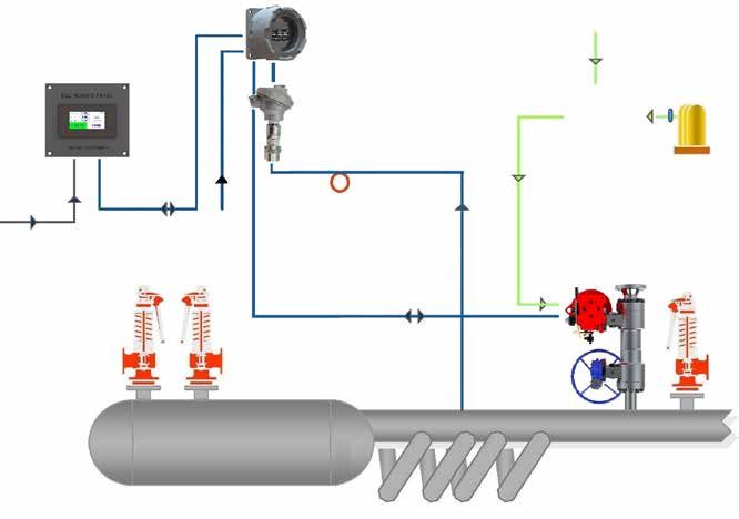
Figure 1 illustrates the relationship of the various inrush current, does not exceed 5%.
elements of the power actuated relief valve system.
The Type 3539 Controller consists of a pressure The field wiring must have insulation suitable for at least
sensing element (i.e., a bourdon tube), an electrical 600 volts. The solenoid insulation is Class F.
relay and control box which houses the electrical relay Environmental Conditions:
and sensing element. The Type 2537 control station
• Indoor or outdoor use
is a three position selector which allows selection of
manual actuation, off or automatic actuation. It consists • Elevation (maximum) 2000 M
of a box, selector switch and two indicator lights (red
• O
perating ambient temperature maximum 140°F
and amber). The pneumatic actuator assembly consists
(60°C). (CE certified at 40°C maximum.)
of a double acting pneumatic actuator, two three-way
solenoid valves (one normally open and one normally • Pollution degree - 2
closed), and one actuator mounted Westlock switch • Over voltage category III
which contains two SPDT limit switches.
• Main supply voltage fluctuations of +10% to -5% of
The electrical supply system consists of a control circuit the normal voltage.
and a solenoid circuit.
• Protection classification
The solenoid circuit provides the voltage needed for - Type 2537 Control Station – Nema (IP)
the solenoid. The solenoid power supply wiring must - Type 3539 Controller – Nema 4 (IP)
be sized so that the voltage drop, due to the solenoid
- Topmount Controller Assy - Nema (IP)
Discharge
3539 Controller
Stack
Shut
Off
Siphon Valve
3500 Series
From Electromatic
Solenoid Ball Valve
Voltage Steam
Header
CLOSED
Supply
Electrical Supply
Drain &
Test Pneumatic Level Isolating
Valve 2537 Gate Valve
Control
Station
Header
Control Voltage Supply
Figure 1: Consolidated Electromatic Ball Valve Systems
VIII.Introduction
The Consolidated Electromatic Ball Valve (EBV) is an When the pressure element is set to open the
electrically controlled pneumatically actuated pressure Electromatic Ball Valve (EBV) at a pressure slightly
relief device. It may be manually operated by closing a below the lowest set spring loaded safety valves, it will
switch, or automatically operated at specified opening prevent the safety valves from opening except during
and closing pressure. The application provides the major overpressure excursions.
plant operator with a means of instantaneously opening
and closing a relief valve at a remote location.
10 | Baker Hughes © 2020 Baker Hughes Company. All rights reserved.IX. Consolidated 3500 Series Safety Valves
Part
Nomenclature
No.
1 Body
12 11 10 19 2
7 22 2 Yoke
6 3 Discharge Collar
8
Ball and Seat
15 4
Assembly
16 4A Seat
4B Ball
9
4C Loader
4D Belleville Washer
5
4E Split Spacer Ring
3 5 Gasket
4D
6 Stem
1 4E 4C 4B 4A 24 14 13 7 Stem Nut
8 Bearing Washer
Figure 2: 3500 Valve Typical Flange Inlet. Packing Gland
9
Flange
19 2
10 Packing Gland
11 Packing Ring
22 16
12 Packing Stop Washer
3
9
Discharge Collar
17 13
10 Studs
18 14 Discharge Collar Nuts
15
12 15 Stud Packing Gland
7
11 16 Nut Packing Gland
8 Cap Screw Yoke/
17
Body
Lock Washer Yoke/
18
Body
19 Drive Bushing
Cap Screw Yoke/
20
Actuator
Lock Washer Yoke/
21
Actuator
22 Key Stem
23 Set Screw
13 14 5 4A 4B 4C 4E 4D 1
24 Drain
Figure 3: 3500 Valve Typical Buttweld Inlet. 25 Actuator Assembly
25A Actuator
© 2020 Baker Hughes Company. All rights reserved. Consolidated 3500-1/2/3 EBV Series POSRV Manual | 11IX. Consolidated 3500 Series Safety Valves (Cont.)
Part
Nomenclature
25K 25L 25L 25K 25A No.
25B Solenoid (Open)
25C Solenoid (Closed)
25D Position Switch
25E Bracket
Cap Screw Bracket/
25F
CLOSED
Actuator
BEACON
Lock Washer Bracket/
25G
CLOSED
Actuator
Cap Screw Bracket/
25H
Switch
25B
Lock Washer Bracket/
25J
25Q Switch
25C
25K Close Nipple Pipe
1/2”-14F NPT
25P 25U 25M 25N 25S 25S 25S 25L Flush Bushing
Conduit Fitting
25M
Straight
25N Pipe Plug
25P Tee Pipe
23
25Q Nipple Pipe 6" Length
19 20 21 25R Elbow Pipe
25S Tubing
17 18
Tube Fitting Union
25T
Elbow
25U Tube Fitting Union
25V Male Branch Tee
25W Male Run Tee
25R 26 Pressure Regulator
27 Filter
28 Nipple Pipe 3" Length
29 Check Valve
CLOSED
25T 25E 25H 25J 25D 25F 25G 25T 25T 30 Cross Pipe
31 Hex Nipple Pipe
Figure 4: Valve Actuator Assembly (GS620/GS628 Actuator)
32 Thread Protector
Note: The drive bushing that connects the LEDEEN GS620 and 628 actuators with the stem of 33 Rupture Disc
the ball valve may float up inside the actuator during re-assembly. A temporary application
(during disassembly), of duct-tape or a 4" hose clamp will hold it in position with about ¾
of an inch of bushing showing below the actuator. Following re-assembly remove any duct-
tape or hose clamp from the drive bushing and ensure that the drive bushing set screw is
tight.
12 | Baker Hughes © 2020 Baker Hughes Company. All rights reserved.IX. Consolidated 3500 Series Safety Valves (Cont.)
25A
CLOSED
BEACON
CLOSED
25B 25U
25C
1/2”-14F NPT
25Q 25P 25U 25M 25N 25S 25S
23
18 17
20 21
22
25R
CLOSED
25G 25F
25T 25K 25L 25E 25H 25J 25D 25L 25K 25T 25T
Figure 5: Valve Actuator Assembly (SY1032/SY1043 Actuator)
© 2020 Baker Hughes Company. All rights reserved. Consolidated 3500-1/2/3 EBV Series POSRV Manual | 13IX. Consolidated 3500 Series Safety Valves (Cont.)
25S 25U 25T 25L 25K 25S
26
25V 1/2” - 14F NPT
25W
CLOSED
28
BEACON
CLOSED 27
Figure 7: Pressure
Regulator and Filter
25S 25S
25B
25R
25C
32 29 33 31
25Q 1/2”-14F NPT 25P 25U 25M 25N 25S
TO
ACTUATOR
FLOW
30
FLOW 29
17 23
18 32
19
20
21 Figure 8: Auxiliary Supply
Manifold
CLOSED
25H 25F
25U 25E 25J 25D 25G 25T
Figure 6: Valve Actuator Assembly (VA123 Actuator)
14 | Baker Hughes © 2020 Baker Hughes Company. All rights reserved.Power Actuated Relief Valve System.
The solenoid insulation is Class F.
The MVC-5000 digital controller consists of a touchscreen display
module and pluggable terminal board, enclosed within a rugged
X. Operating Principles
NEMA 4X/IP68 aluminum or stainless steel window housing. Local
indication is provided for AUTO/OPEN mode selection, real-time
pressure display, set and reseat pressure.
Digital Controller Retrofit for 3500-1/2/3 EBV
MVC-5000 Digital Controller Digital
Controller Instrument Air Supply
(Standard 80 psig)
(40 psig min. - 120 psig max.)
Remote Panel
(Optional)
Optional
Transducer Manifold
System
Syphon
Nitrogen Tanks
Control w/Regulator
Voltage
System
Supply
Supply Electromatic Safety
Voltage Ball Valve Valve
Isolation Ball
Valve
Super Heater
Boiler Drum
Figure 1: Typical Electromatic Ball Valve System
© 2017 General Electric Company. All rights reserved. Consolidated 3500-5 Series EBV Instruction Manual | 9
In the “PARV” configuration, the MVC-5000 operates as a sophisticated digital pressure switch. While
continuously monitoring process pressure through a high-precision ADC, the MVC-5000 automatically
operates a power actuated relief valve according to the user’s programmed set pressure and
blowdown criteria. This configuration can be used to control ASME and non-ASME capacity certified
EBVs. The EBV configuration also includes provisions for DCS and manual override. For more
information please visit the following links:
MVC-5000 GENERATION 1 (Produced before August 2018)
Datasheet:
https://a-tcontrols.com/Documents/2064/MVC-5000%20Datasheet%20GE%20R5%20(new).pdf
IOM:
https://a-tcontrols.com/Documents/2065/MVC-5000PARV%20-%20IOM%20R6.pdf
MVC-5000 GENERATION 2 (Produced after August 2018)
Digital Controller
Datasheet:
https://a-tcontrols.com/Documents/1787/MVC5000%20PARV%20Catalog-20181004.pdf
IOM:
https://a-tcontrols.com/Documents/1792/IOM08085%20-%20MVCG2%20PARV_Rev02.pdf
© 2020 Baker Hughes Company. All rights reserved. Consolidated 3500-1/2/3 EBV Series POSRV Manual | 15X. Operating Principles (Cont.)
External Switchbox
The ASME certified MVC-5000 housing is sealed closed after installation, leaving the local
touch screen inaccessible in normal operating conditions. The MVC-5000 switch box is a simple
bolt-on that outfits the MVC with local hand controls so that the operator can control the device
without removing the cover. Each box contains a three position, normally closed, selector switch.
Two positions initiate commands (AUTO and OPEN), while the third mid position removes both
commands from the MVC so that other devices may take control.
Digital Controller
• Ingress Protection: NEMA 4X, IP66
with External Switchbox
Remote Panel Options
The remote panels, which are offered in two varieties (DCS push buttons and Modbus
touchscreen), are small units that can be mounted on the plant control panel. The DCS control
station is hardwired to the MVC’s discrete I/O, while the Modbus control station is connected to the
MVC’s RS-485 serial port. Both versions provide for remote control and communication with the
MVC-5000.
DCS Remote Panel
The DCS remote panel consists of two lights and a three position switch. The Open and Closed
lights indicate actual valve position. The selector switch is used to command the controller either
in Auto Mode or Open Mode. In Auto Mode, the controller operates the valve autonomously in
response to system pressure. In Open Mode, the controller manually opens the valve, regardless of
system pressure.
• Ingress Protection: IP65 (panel mounted) DCS
Remote Panel
Modbus Touchscreen Remote Panel
The Modbus touchscreen remote panel consists of a 3.5” color touchscreen, which duplicates the
local MVC-5000 touchscreen display. Commands and feedback are sent through the MVC-5000’s
RS-485 Modbus link. Auto/open Modes and device configuration parameters can all be set from
the Modbus control station. Set/Reseat and actual system pressure are also relayed to the control
station for remote readout.
Modbus
• Ingress Protection: IP66 (panel mounted) Touchscreen
Remote Panel
16 | Baker Hughes © 2020 Baker Hughes Company. All rights reserved.X. Operating Principles (Cont.)
Electrical System completes the relay circuit that energizes the valve
solenoid. The low pressure switch D then provides
The EBV is a 90 degree turn "open to close,” electrically for relay control below the actuation value of the high
controlled, pneumatically actuated relief valve. pressure switch, thereby allowing an adjustable blow
Automatic actuation at a predetermined set pressure is down for the Electromatic Valve. This action makes
accomplished by a Type 3539 controller. extremely sensitive regulation possible.
The field wiring must have insulation suitable for at The Type 2537 control station, which includes a switch
least 600 volts. and two lights, Is a small unit that can be mounted in a
control panel.
The Type 3539 controller is actuated by the pressure
in any vessel to which it is connected. The construction The control station is electrically connected to the Type
of the controller is such that it will make and break 3539 controller. With the control station Switch in the
electrical contact with a difference in pressure of 1-1/2% "automatic" position (see Figure 10), the "amber" light
of the "set pressure." Within the controller (see Figure turns on and remains on until the valve is opened.
9) is the dual control pressure switch.
When the pressure reaches the predetermined point,
Adjusting screws A and B determine the operating at which the valve is set to open, contact is made in
point of each switch. When the pressure increases to the Type 3539 controller, resulting in the relay closing.
the "set point," high pressure switch C is actuated and
ELECTROMATIC RELIEF VALVE
TYPE 2537 CONTROL STATION
E
MOV
WHIT
PURPLE
ITE
RED
WH
RED
RED
RED AMBER
W
HI
TE
VALVE VALVE
BR OPEN CLOSED
D OW
N
MAN.
OW
LL
OFF
YE
ATTACH G
E
RED
RED OR BLACK
N
TO GROUND BL RA
UE O RED AUTO
LUG ON DOOR
D
RE
C E
B A
Figure 9: Type 3539 Controller Figure 10: Type 2537 Control Station
Accordingly, the solenoid valves are energized, and When it is desirable to open the valve "manually," this
the valve opens. At this time the "red" light in the Type can be accomplished by simply pushing the Control
2537 control station turns on which indicates that the Station Switch to the "manual" position. To close the
valve is open. When the pressure decreases below valve, it is only necessary to push the control station s
the adjusted closing point of the valve, the relay de- witch to the "off" position.
energizes and this, in turn, de-energizes the solenoid
Note: Remember that when the switch is in the
valves, and causes the valve to close. The "red" light in
"automatic" position, the valve will open at
the Type 2537 control station will then go off, and the
the predetermined pressure for which it is
"amber" light will go on. The lights on the control station
set.
are controlled by a position switch on the actuator.
© 2020 Baker Hughes Company. All rights reserved. Consolidated 3500-1/2/3 EBV Series POSRV Manual | 17XI. Recommended Installation Practices
A. Main Valve
The power actuated relief valve is customarily installed either on a superheater,
or on a manifold fed by two or more boilers. To facilitate servicing, an isolation
Support
valve should be installed directly below the main valve, as shown in Figure 11.
(Refer to ASME Code Restrictions for code stamped valves).
Discharge
Care should taken to ensure that mechanical strains from the discharge piping Stack
Drain
are not transmitted to the EBV. Such strains are detrimental to good valve
performance. The discharge pipes should have adequate steam capacity and
should be of a size to provide for movement caused by thermal expansion.
Discharge piping should be drained to prevent the accumulation of water in the
valve outlet. At no time should the discharge piping bear against the drip pan, or 3500 Ball
the nipple therein. The riser piping should be securely anchored to the building Valve
structure, and never to the valve, in order for it to resist the reactive forces of the Wear necessary
discharged steam. The drains should be piped in such a manner as to prevent the protective equipment to
unnecessary escape of steam into any enclosure, and to keep foreign material prevent possible injury
from being blown back into the valve from other sources (Refer to Figure 11).
Cover the main valve outlet, during system shut downs, when the valve is not
in service, or is not pressurized, to prevent foreign matter from entering into the
main valve.
B. Type 3539 Controller
Care must be taken in mounting the controller, since it will not operate properly if
subjected to vibration. It is recommended that the controller be mounted directly to
the building structure and, depending on the installation, it may even be advisable
to mount the controller on some type of shock absorbing material, in order to
isolate it from the any vibration in the building structure. Since the sensing line
from the pressure vessel may also transmit vibrations to the controller, precautions
should be taken to eliminate this possibility.
Before disassembling
Support the valve, ensure there is
no media pressure in the
vessel.
Discharge
Stack
Drain
CLOSED
Valve caps and bonnets
can trap fluids. Use
3500 caution when removing
Ball Valve to prevent injury or
environmental damage.
Figure 11: Recommended Exhaust Stack Installation
18 | Baker Hughes © 2020 Baker Hughes Company. All rights reserved.XI. Recommended Installation Practices (Cont.)
Baker Hughes suggests that several loops of high- C. Required Wire Gauge
pressure tubing be used to accomplish this task. Further,
the pressure sensing connection should be mounted The electrical supply to the controller (solenoid voltage)
at least eight to ten pipe diameters upstream from should have stranded wiring. The wire should be no
the EBV in order to provide a stable pressure signal. smaller than 12 AWG. If necessary, the wire should be
Finally, if the controller may be subjected to freezing larger than 12 AWG, to prevent more than a 5% voltage
temperatures, a heating element should be added to drop to the solenoid inrush current.
prevent freezing of the bourdon tube.
Table 1: Optional Voltage
Type Voltage Frequency Amperage
100 – 240 AC 50 – 60 Hz .3
3500 Ball Valve
24,48,100 – 240 DC N/A 1.0
WELDING CAUTION
This valve contains a ball and seat assembly that has been coated for wear
resistance and may be damaged if exposed to elevated temperatures associated
with welding and post weld heat treatment. Welding interpass temperatures should
be in compliance with ASME B&PV Code Section IX but should not exceed 570°F
(299°C). Local post weld heat treatment of the weld and heat affected zone is
recommended. If this entire valve body is to receive post weld heat treatment, the
hall and seat assembly should be removed. The bushing gasket must not be reused
after disassembly. Refer to valve service manual of disassembly and assembly
instructions.
D. Cable - Special Conditions of F. ASCO Solenoid - Special
Use Condition of Use
In order to prevent mechanical damage of the un- The flameproof joints are not intended to be repaired.
armored cable, the equipment shall be installed, so far
as practical, in a position that will prevent exposure to
mechanical damage.
E. L
imit Switch Enclosure -
Special Condition of Use
The hexagonal head cover screws on the Topworx® limit
switch enclosure are to be replaced only with stainless
steel A2-70 or A4-80 screws to ISO 35061.
The cover fasteners on the Topworx® limit switch
enclosure are to be tightened to a torque value of 10.85
Nm (8ft/Ibs) minimum.
© 2020 Baker Hughes Company. All rights reserved. Consolidated 3500-1/2/3 EBV Series POSRV Manual | 19XII. Disassembly of 3500 Series Safety Valve
CAUTION: 3. Loosen and remove the body stud
nuts.
Make sure that no pressure is in the valve
4. Lift the discharge collar off the
prior to disassembly. If equipped with
valve.
an isolation valve, close the isolation
5. Two threaded holes are provided
valve and actuate the EBV valve open
so that a bolt or all-thread can
and closed to remove all pressure. If not
be used to remove the seat. The
equipped with an isolation valve, the unit
1.5” (38.1 mm) and 2” (50.8 mm)
must be shut down prior to disassembly.
size valves are tapped with a
#10-32 thread. The 2.5” (63.5 mm)
size valves are tapped with a 0.25”
A. Ball, Seat and Loader (6.35 mm)-20 thread. Screw two
Assembly Removal bolts or two pieces of all-thread into
Refer to Figures 2 and 3 the threaded holes. Lift the seat out
of the body.
1. If the ball, seat and loader assembly is 6. Using two lifting hooks illustrated
to be removed while on the unit and the in Figure 12, remove the ball. This
installation is equipped with an isolation is accomplished by inserting the
valve, close the isolation valve. Actuate hooked end into the flow port of the
the EBV from open to close to relieve ball and lifting upward.
any pressure between the EBV and the 7. Insert the hook end of one of the
isolation valve, if not equipped with an lifting hooks under the sear loader
isolation valve, the unit must be shut down and rotate the loader until it’s bore Figure 12: Ball
prior to disassembly. is perpendicular to the body bore. Placement and
2. If disassembling on the unit, remove the Lift the loader up and out of the Removal Tool
discharge stack. If the valve is not in the body. (Make Locally)
closed position. 8. Remove the Belleville washer and
the split ring spacer.
CAUTION:
Do not actuate the valve with the collar
removed. Damage to the ball may result.
B. Actuator Assembly Removal
Refer to Figures 4, 5 or 6
1. hut off the service air line and disconnect it from
S Note: Do not connect a lifting device to the Westlock
the actuator. switch, solenoid valves or tubing. Hook a
chain hoist or other suitable lifting device
2. hut off the electrical supply to the actuator
S
to the strap sling. Adjust the hoist until no
mounted Westlock switch. Disconnect electrical
slack is in the line. Loosen and remove the
wires and conduit coming from the controller to the
four actuator mounting bolts connecting the
Westlock switch.
yoke to the valve body. Slide the actuator and
3. Attach a strap sling around the cylinder portion of yoke assembly away from the valve until the
the actuator at the end near the housing. mounting yoke is clear of the drive bushing.
20 | Baker Hughes © 2020 Baker Hughes Company. All rights reserved.XII. Disassembly of 3500 Series Safety Valve (Cont.)
C. Stem Removal Retainer Plate
Refer to Figures 2 and 3
Part No Used On
1. Apply a temporary piece of duct-tape or a 4” (101.6 4949001 3515, 3516, 3525,
mm) hose clamp to the drive bushing to prevent 3526
it from floating up into the actuator. Approximately 4947001 3517, 3527, 3537
.75” (19 mm) of the drive bushing should show 4946901 3538, 3547
below the actuator.
2.
Loosen the allen head set screw in the drive
bushing. Slide the bushing off the stem and remove
the drive key.
3. Loosen and remove the two packing gland stud
nuts. Remove the packing gland flange and the
packing gland.
4.
Using a wire hook or screw driver, dig out the
316 stainless steel with flexible graphite fillers
(spiral wound) packing. The packing stop washer
is drilled and tapped with two #10-32 threaded
holes. Screw a piece of all-thread or a #10-32
screw approximately 3" (76.2 mm) long into one Figure 13b: Retainer Plate
of the holes in the packing stop ring. Slide the
packing stop ring off the stem. The stem nut can
now be removed using the stem nut wrench, 5.
Remove the stem and bearing washer from the
illustrated in Figure 13a and 13b. Rotate the nut body.
counterclockwise to remove it. D. Cleaning
The 3500 Series EBV Valve parts may normally be
cleaned with wire brushes, and low pressure air.
Stem Nut Removal Tool Whatever method is used, clean the parts safely and
Part No Used On use care to prevent damage to the environment. If
4948901 3515, 3516, 3525,3526 internal parts are cleaned with industrial solvents or
4947101 3517, 3527, 3537
cleaning solutions, take precautions to protect yourself
from potential danger of
4945701 3538, 3547
breathing fumes, chemical
burns, or explosion.
See the manufacturer’s
Safety Data Sheet for
safe handling instructions
and information about
protective clothing and
equipment for use when
working with the chemical.
The outside surfaces of
the actuator, Type 2537
control station, and Type Follow recommendations
for safe handling in the
3539 controller box may
solvent's Safety Data
be cleaned by wiping with Sheet and observe
a damp cloth. safe practices for any
cleaning method.
Figure 13a: Stem Nut Removal Tool
© 2020 Baker Hughes Company. All rights reserved. Consolidated 3500-1/2/3 EBV Series POSRV Manual | 21XIII. Maintenance Instructions
A. Seat Leakage B. Packing Leakage
If leakage should occur use the following procedure to Should packing leakage occur, tighten the two packing
determine and correct the cause: nuts in the quarter turn increments. Check after each
1.
Verify that the normally closed solenoid valve is quarter turn adjustment to see if leakage has stopped.
energized and vented. To accomplish this, check The packing should be tightened only enough to stop
the voltage across terminal 2 and 3 in the actuator the leakage.
junction box. There should be voltage at these If the leakage can not be stopped by tightening the
terminals when the valve is closed. If no voltage is gland nuts, the valve should be repacked with new
present, check continuity across terminals 3 and 4. packing. The valve can be repacked without removing
There should be continuity across these terminals the actuator and actuator yoke if split ring service ring
when the valve is closed. If there is no continuity, packing is used. Refer to Table 2 for part numbers. The
adjust the closed side actuator switch lever cam until EBV can also be repacked with 316 stainless steel(1)
the circuit is closed. Actuate the valve and check for rubber pack. If the EBV is equipped with an isolator
leakage. valve it must be closed to isolate the EBV. Open the
2.
If the switch is properly adjusted and leakage EBV from open to closed to relieve pressure with an
continues, the ball and seat assembly must be isolation valve, the unit must be shut down.
removed and checked. The valve must be isolated Loosen the packaging gland bolts one full turn. Wait
from system pressure before it can be disassembled. approximately two minutes to verify that the gland and
Using the procedures outlined in the disassembly flange does not move and reload the packing gland
section of this manual remove the adapter flange, nuts. Loosen the actuator drive bushing lock screw and
ball, and seat assembly. Inspect the spherical move the bushing away form the packing gland flange
radius in the seat for cutting or flaking of the chrome enough to slow removal of the packing gland slud nuts.
carbide. Inspect the spherical radius of the ball for Move the packing gland flange and packing gland
cutting or flaking of the chrome carbide. Very light away from the stuffing box until the flange contacts the
flaking at the edge of the bore is acceptable. If the yoke. Using a wire hook similar to the one illustrated
seat is damaged and the ball has galling or flaking in Figure 12, or a packing remover, remove the 316
of the carbide coating the entire ball and seat and stainless steel1 packing from the stuffing box. Place the
loader assembly must be replaced. Remove the old split ring packing around the stem below the packing
gasket and clean the gasket surfaces of the body gland. Use the gland to position the packing in the
and the busing. Reassemble the valve using the stuffing box. The correct number of rings is specified in
procedures outlined in the assembly section of this Table 2. Install the packing gland nuts and tighten. Final
manual. Pressurize and actuate the valve. Check for adjustment must be made after the valve is pressurized.
leakage. Tighten just enough to prevent leakage.
3. If a new ball, seat and loader assembly has been
installed and the valve still leaks, the stem bearing
pad must be replaced. Refer to the disassembly and
assembly section of this manual for disassembly
and assembly instruction. The valve must be
isolated from system pressure when removing and
replacing the stem bearing pad. New packing must
be installed each time the stem is removed.
1. With Flexible Graphite Fillers (Spiral Wound)
22 | Baker Hughes © 2020 Baker Hughes Company. All rights reserved.You can also read