Prism PM Compact and modular with integral pneumatic control
←
→
Page content transcription
If your browser does not render page correctly, please read the page content below
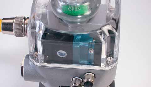
Prism PM

Prism PM
Compact and modular with integral pneumatic control
The Prism series, designed for          Ideally suited for process                         Wide variety of switching and
corrosive process environments,         environments                                       communication options
                                        The Prism features a durable polycarbonate         The Prism features a full range of feedback
attaches directly to sanitary           enclosure suitable for both general purpose        options in the fully sealed, solid state
diaphragm and angle valves.             and hazardous process environments. The            dual module. Select the SST sensors for
This rugged, feature-rich               integral pneumatic control is completely           conventional switching, NAMUR sensors
platform offers a full array of         isolated within the enclosure on a stainless       for intrinsically safe applications or
                                        steel reinforced polysulfone manifold so           communication options including AS-
communication and switching             standard tube fittings may be reliably             Interface, DeviceNet™ and Foundation
options, as well as discrete integral   attached. And the Prism is rated for               Fieldbus. All switching sensor and
pneumatic control for single-           nonincendive or intrinsically safe applications.   communication modules are fully solid
acting valve actuator operation.                                                           state and sealed for high reliability.
                                        Readily adaptable to linear valves
                                        Stainless steel mounting systems are
                                        available for adapting the Prism to
                                        sanitary and industrial diaphragm, as
                                        well as angle valve applications. Stroke
                                        lengths from as low as ¼” to as long as
                                        2” may be readily accommodated.

62 | Valve communication & control                                                                                            StoneL.com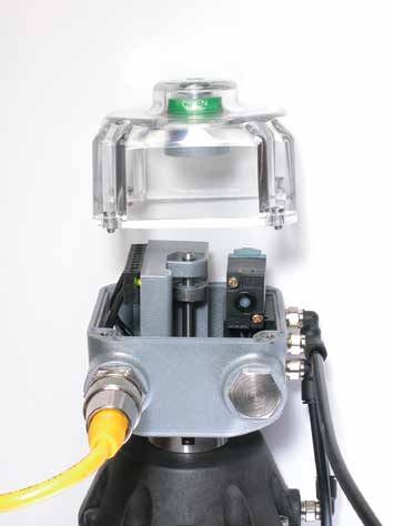
Prism PM

Features
1. The Prism may be washed down and temporarily
   submersed with no adverse affects. It is rated NEMA 4, 4x, and 6.
    It may be used in Div. 2 (nonincendive) or Div. 1 (intrinsically safe)
    hazardous applications.
2. Enclosure features high strength polycarbonate with
    excellent corrosion-resistance and exceptional temperature
                                                                               2
    stability.
3. Visual electronic and mechanical position indication                                                                                         1
    confirm valve and switch status for added safety.
                                                                               3                                                                4
4. Solid state proximity sensors monitor open and closed                                                                                   5
    discrete valve position with precision and reliability.
                                                                               7                                                                6
5. Integral pneumatic valve is isolated from environmental                                                                                 8
    contamination, offers high tolerance to dirty air and enables rapid        9
    valve operation.                                                                                                                           10
6. Solenoid options available for 120 VAC and 24 VDC. Select piezo
                                                                              11
    option for bus powered Foundation Fieldbus applications.
7. Self-adjusting triggering system provides consistent open
    and closed indication even with diaphragm compression. No
                                                                                                                                               12
    resetting is required.
8. Manual override enables valve operation without electrically
    energizing.
9. Dual module system seals all position sensing, communication              11. Waterproof quick connectors, compression fittings or
    and control electronics in a compact vibration proof package.                conduit connections are available for convenient, reliable
                                                                                   attachment to plant electrical systems.
10. NPT port connections are stainless steel reinforced for
    long life sealing under high torque stress conditions.                   12. Stainless steel adaptor system locks Prism securely to valve
                                                                                   actuator and provides stability for shaft interface.

Self adjusting triggering system
Triggering cams adjust automatically over the valve diaphragm operating life. Cams are fitted snugly to
the shaft assuring stability under high amplitude vibration at varying frequencies and temperatures.
Self adjustment sequence
1. Installation                                     2. Automatic initial setting                                  3. Operational self adjustment
    Cams are manually set to outer limits               On operation, cams are automatically                          As diaphragm compresses
    when fitted to actuation system.                    positioned to proper set points by module                     over time, closed cam is
    (Open at top; closed at bottom)                     stops at top and bottom.                                      automatically repositioned.

+1 218 739 5774                                                                                                   Valve communication & control | 63
Prism PM
Sensing and communication module
The Prism features StoneL’s dual module system with field proven reliability
in all on/off applications. Outputs are available as NAMUR (intrinsically
safe), SST (switching) and VCTs (valve communication terminals).
Dual modules have a five year warranty.
Switching and sensor specifications Valve Communication Terminal (VCT) specifications
SST switching sensors (33, 34) AS-Interface (96)
Configuration (2) SST solid state sensors Configuration (2) Discrete sensor inputs
(2) Wire terminations for one solenoid (2) Auxiliary discrete inputs
(2) Power outputs (solenoids)
Operation Select either NO (33) or NC (34) models
Maximum current 160 mA, both outputs combined
Maximum current inrush 1.0 amps @ 125 VAC/VDC
Auxiliary inputs 24 VDC @ 2 mA (self-powered)
Maximum current continuous 0.1 amps @ 125 VAC/VDC
Output 4 watts @ 24 VDC both outputs combined
Minimum on current 2.0 mA
Outputs, voltage 21 - 26 VDC
Maximum leakage current 0.5 mA
Configuration code ID=F, IO=4; user defined (4DI/2DO)
Voltage range 24 - 125 VAC
8 - 125 VDC AS-i version 3.0
Maximum voltage drop 6.5 volts @ 10 mA Devices per network 31
7.5 volts @ 100 mA
Wiring diagram AS-i +
Wiring diagram (96) AS-i -
Solenoid 1
Solenoid Valve Output AUX IN +
(33, 34) 2
AUX IN1 -
SST
Solenoid 1
Power AUX IN2 -
2
3 WIRE RTN
Valve Open
OUT2 +
Common Solenoid Valve OUT2 -
Valve Closed
OUT1 +
Common Solenoid Valve OUT1 -
NAMUR sensors (44)
AS-Interface VCT with extended addressing (97)
Configuration (2) NAMUR sensors (EN 60947-5-6; I.S.)
(2) Wire terminations for one solenoid Configuration (2) Discrete sensor inputs
(2) Auxiliary discrete inputs
Operation Normally closed NAMUR sensors (solid state) (1) Power output (solenoid)
Voltage range 5 - 25 VDC Maximum current 100 mA
Current ratings Target on I3 mA
Output 2 watts @ 24 VDC
Wiring diagram Solenoid 1
Solenoid Valve Output Output, voltage 21 - 26 VDC
(44) 2
NAMUR
1 Configuration code ID=A, IO=4; user defined (4DI/1DO)
Solenoid
Power 2 AS-i version 3.0
Valve +
open
Devices per network 62
-
Valve + Wiring diagram AS-i +
closed - (97) AS-i -
AUX IN +
AUX IN1 -
AUX IN2 -
3 WIRE RTN
NOT USED
NOT USED
OUT1 +
Solenoid Valve OUT1 -
64 | Valve communication & control StoneL.com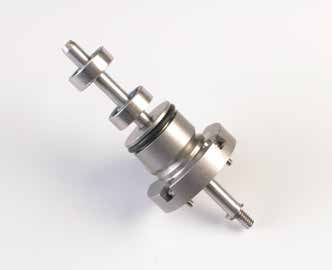
Prism PM

Sensing and communication module
 Valve Communication Terminal (VCT) specifications                                 Valve Communication Terminal (VCT) specifications
 Foundation Fieldbus VCT, bus powered (93)                                         DeviceNet™ (92)
 Configuration                    (2) Discrete Inputs                              Configuration          (2) Discrete inputs (open and closed)
                                  (2) Power outputs (solenoids)                                           (2) Power outputs (solenoids)
                                  Multiple DI/DO blocks or modified output block                          (1) 4-20 mA auxiliary analog input, 10-bit
                                                                                                          resolution; no additional power source required
 Outputs                          2 mA @ 6.5 VDC each
                                  current limited to 2 mA (bus powered)            Transmission rate      Software selectable 125K, 250K or 500K baud
 Devices per network              Max of 16 devices recommended                    Messaging              Polling, cyclic and change of state
 Wiring diagram                                                    FB +            Outputs                4 watts @ 24 VDC outputs combined
  (93)                                                             FB -
                                                                                   Outputs, voltage       24 VDC (with input voltage ranging from
                                                                OUT1 +                                    10 - 24 VDC)
                                      Solenoid Valve            OUT1 -
                                                                OUT2 +
                                                                                   Other features         Predetermined output fail state
                                      Solenoid Valve            OUT2 -             Wiring diagram                                                V+
                                                            SIM JMPR                (92)                                                  CAN H
                                                            SIM JMPR                                           DeviceNet                 SHIELD
                                                                                                                 Bus
                                                                                                                                            CAN L
                                                                                                                                                 V-
                                                                                                                                                Ain -
                                                                                                               4-20 mA
                                                                                                              Transmitter                       Ain +
                                                                                                                                            OUT1 -
                                                                                                             Solenoid Valve
                                                                                                                                         24 VDC +
                                                                                                                                            OUT2 -
                                                                                                             Solenoid Valve

+1 218 739 5774                                                                                             Valve communication & control | 65
Prism PM
Pneumatic control and other specifications
The three-way, two-position spring return pneumatic valve is
Specifications
designed to operate single acting actuators. Working mechanisms
General pneumatic (solenoid & piezo)
on the valve are completely isolated from the environment enabling
pneumatic control to be located in the field at the actuator with no Configuration 3-way, 2-position, spring return
threat of contamination. A standard rebreather enables exhaust air Porting 1/8" NPT all pressurized ports
from the pressurized actuator Rebreather port 4-40 size
Valve schematic
cylinder to be channeled Flow ratings 0.1 Cv
into the spring side actuator Rebreather Standard on all models; diverts air from exhausting
chamber preventing the cylinder into actuator spring side. Excess air
P E1 E2 ingestion of contaminated air exhausted into atmosphere.
from the outside environment. Operating life 1 million cycles
Select a solenoid valve for Operating pressure 40 psi to 120 psi (2.6 to 8 bar)
conventional or device bus
A
applications or a piezo valve
for Foundation Fieldbus bus
powered applications.
Piezo valve
Solenoid valve The piezo valve is ideally suited for use
A poppet style valve with exceptional with the Foundation Fieldbus (FF) bus
tolerance to dirty air, the solenoid valve powered output module (93). Each
may be used for most conventional module output provides up to 2 mA @
AC or DC applications. The DC (low 6.5 VDC which is sufficient to drive the
power) version may be used on AS- piezo valve. Specifically designed for on/
Interface and DeviceNet™ bus powered off discrete applications, the piezo valve
applications and on Foundation Fieldbus may remain energized for extended
(94) externally powered applications. periods of time with no memory effect.
Specifications Specifications
Solenoid valve (1C, 1D, and 1E coil options) Piezo valve (1A, bus powered Foundation Fieldbus)
Filtration requirements 40 micron Filtration requirements 30 micron
Operating temperature -18° C to 50° C (0° F to 120° F) Operating temperature -10° C to 60° C (14° F to 140° F)
Power consumption See model selector guide DC power requirements 2 mA @ 6.5 VDC
Prism mounting system*
Prism adapting systems are designed specifically for
each actuator manufacturer and model. The adaptor
coupling, made of stainless steel, also integrates a Triggering cams
corrosion proof, ultra long-life bushing. This system
stabilizes the shaft from lateral motion and assures
reliable, low friction movement over the actuator’s life. Long-life bushing
Stainless steel coupling
• Required for all
• Order kit separately
Stainless steel fasteners
• For kit numbers, consult factory or visit StoneL.com
Note: Kit numbers are specific to valve size and manufacturer. Stainless steel shaft
* Open travel stops recommended on diaphragm actuators to maintain
consistent travel with varying process line pressures.
66 | Valve communication & control StoneL.comPrism PM
Other specifications Model selector
Materials of construction SERIES
Housing and cover Polycarbonate PM Nonincendive or intrinsically safe
Fasteners Stainless steel FUNCTIONS
Triggering cams Stainless steel banded polycarbonate Sensor modules
Shaft Stainless steel 33 (2) SST NO switching sensors [select pneumatic valve option 1C, 1D or 11]
(2) NAMUR sensors (EN 60947-5-6; I.S.) [select pneumatic valve option 1E
Valve manifold Polysufone with stainless steel reinforced NPT 44
or 11]
Operating life 1 million cycles
Valve Communication Terminals (VCTs)
Temperature range -40° C to 80° C (-40° F to 176° F) 92 DeviceNet™ [select pneumatic valve option 1D or 11]
with solenoid Maximum ambient 50° C (120° F)
Foundation Fieldbus (bus powered; I.S.) [select pneumatic valve option
93
Warranty 1A or 11]
Dual module Five years 96 AS-Interface [select pneumatic valve option 1D or 11]
AS-Interface with extended addressing [select pneumatic valve option 1D
97
Other mechanicals Two years or 11]
PNEUMATIC VALVE [consult factory for extended temperature]
Ratings 11 No pneumatic valve
1A Three-way piezo
Nonincendive PM models*
(Ex n, Zone 2 or Class I and II, Div. 2) 1C Three-way 120 VAC 5.4 watt
Intrinsically safe Functions 44 and 93* 1D Three-way 24 VDC 0.5 watt
(Ex ia, Zone 0 or Class I and II, Div. 1) 1E Three-way (I.S.) 12 VDC 0.5 watt
Enclosure protection
CONDUIT ENTRIES
NEMA 4, 4X and 6 All models
S02 (2) 1/2” NPT
Ingress Protection 67 All models S05 (2) M20
Approvals* See StoneL.com/approvals S09 (2) cable glands
* Only models listed on StoneL's official website are approved per specific rating. S11 (1) 5-pin mini-connector
S13 (1) 4-pin micro-connector
S14 (2) 4-pin micro-connector
S15 (1) 5-pin micro-connector
Dimensions Inches [mm] VISUAL INDICATOR
R Green open
VALVE SIZE
S 1/4” to 2” (1/8” to 1 3/16” stroke)
L 2” to 4” (1 3/16” to 2 1/4” stroke)
Model number example
PM 33 11 S02 R S – OPTIONAL
MODEL NUMBER PARTNERSHIP ID
Mounting hardware required and sold Some models may include
separately. 5-digit identification suffix.
+1 218 739 5774 Valve communication & control | 67You can also read