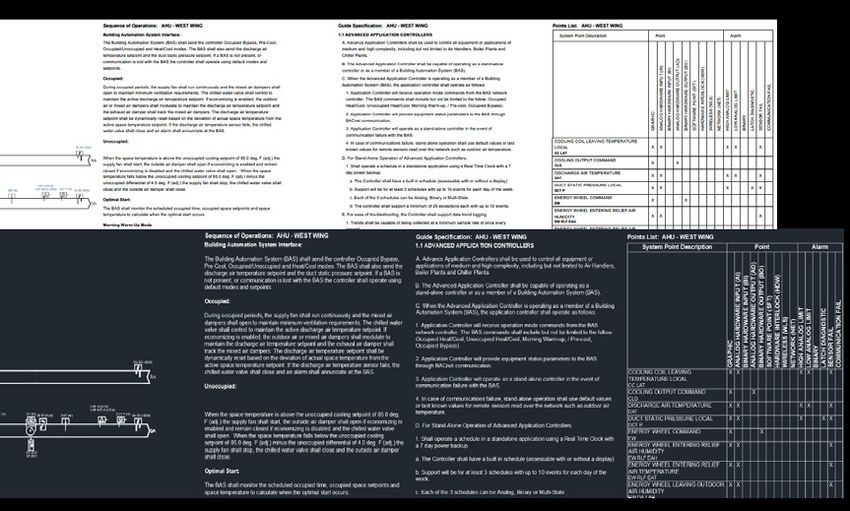
Comprehensive Chilled-Water System Design - System Catalog - Trane
←
→
Page content transcription
If your browser does not render page correctly, please read the page content below

Comprehensive Chilled-Water
System Design
System Catalog
Disconnected Loads Can’t Use Energy

                          Chilled-water systems provide customers           Repeatable, simple yet flexible
                          with flexibility for meeting first cost and       Tracer® chiller plant controls provide
System Components,                                                          sequencing and advanced optimization
                          efficiency objectives, while centralizing
p. 3                                                                        strategies to reduce energy use, with intuitive
                          maintenance and complying with or
                          exceeding energy code minimum                     dashboards that explain what the system is
System Overview,
                          requirements. A comprehensive approach            doing and why.
p. 4
                          to system design can minimize the power
                          draw of the entire system are inherently          Pump, valve and cooling tower controls,
Selecting a Design
                          easier to control for highest efficiency, lower   as well as terminal units, air-handlers and
Configuration,
                          first costs and lower energy costs. Right-        zone sensors can communicate wirelessly.
p. 6
                          sizing equipment means smaller electrical         Air-Fi® wireless controls make construction
                          connections—a great way to do more with           management easy—there’s no need to delay
Chillers, p. 12
                          less. Less money and less energy.                 wall or ceiling installation for control wiring.
                                                                            Air-Fi also leads to better reliability, with self-
Cooling Towers,
                          State-of-the-art design                           healing mesh networking, and easy sensor
p. 22
                          Chilled-water systems employing the best          relocation to accommodate future space use
                          practices in this catalog align with current      changes.
Coil Selection,
                          industry guidance for high-performance,
p. 32
                          all while reducing first cost. By judiciously     By using industry-leading applications such as
                          applying advanced technology and controls,        Tracer® chiller plant control, all projects benefit
UniTrane® Vertical
                          state-of-the-art doesn’t lead to high             from the experiences of others.
High-rise Fan Coil,
                          complexity or algorithms that are difficult to
p. 36
                          understand. In fact, it’s quite the opposite.     Sustained high performance
                                                                            Best practices in chilled-water system
Pumps, p. 38              Efficient, reliable, cost-effective               design take advantage of the capabilities of
                          Chilled-water systems provide the ultimate        the components, unlocking system design
Hydronic System           in flexibility and efficiency for achieving       attributes that lead to high performance that
Accessories, p. 50        cooling, heating, and ventilation. Larger         lasts from year one to year sixty. While many
                          motors are more efficient, and centralized        chillers are themselves still operating sixty
Pipe Sizing, p. 52        systems have fewer moving parts and higher        years later, pipes and other elements regularly
                          reliability. Chilled-water systems have long      do. Systems designed this way are resistant
Control Valves,           lives and centralized maintenance.                to developing and suffering from low-delta
p. 54
                                                                            T syndrome, in which chilled-water systems
                          These design practices are also cost              lose valuable cooling capacity and operate
Tracer® Chiller Plant
                          effective—better design choices lead to           inefficiently.
Control, p. 60
                          fewer pounds of piping and water, smaller
                          cooling towers, pumps, transformers,              Trane chillers, chilled-water coils and
Trane Design
                          power wiring, which in turn lead to               terminals are available in a range of
Assist™, p. 62
                          additional savings in pipe hangers,               efficiency tiers to match your budget and
                          building structure, and more.                     energy goals.

         Trane believes the facts and suggestions presented here to be accurate. However, final design and applica-
         tion decisions are your responsibility. Trane makes no representation or warranty, express or implied and
         expressly disclaims any responsibility for actions taken on the material presented. No licenses are hereby
2        granted either directly or indirectly under any patents, trademarks, copyrights, know-how, or otherwise.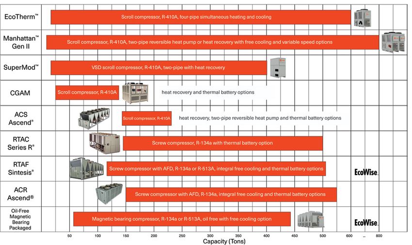
System Components

                                                                            Best practice and code compliant system components
                                                                            • Coils with high (15°F+ ΔT) water temperature rise
                                                                            • Turbulators to improve coil full- and part-load performance
                                                                            • Pressure-independent control valves to eliminate the need for
                                                                               balancing valves and to guarantee full and part load delta T
                                                                            • Pre-programmed, factory-commissioned Tracer® DDC controls
                                                                               with wired or Air-Fi® wireless communications

images courtesy of Flow Control Industries and Armstrong Fluid Technology

                                                                            Chillers
                                                                            • Industry leading full and part load efficiency
                                                                            • Three compressor types (scroll, helical-rotary, centrifugal)
                                                                            • Current and next generation refrigerants available now
                                                                            • Variable water-flow compatible
                                                                            • Pre-engineered, factory-assembled, and factory-tested
                                                                            • Customized configurations and options, efficiency tiers
                                                                            • Variable- and fixed-speed compressors

   Completion Modules

                                                                            Cooling towers
   A chilled-water system
   has many parts, and a                                                    • 14°F+ cooling-tower range to save energy and cost
   good portion of these can                                                • 50 percent or better cooling tower water turndown for
   be pre-assembled, tested                                                    efficient staging, waterside free cooling support and code
   and shipped together for
                                                                               compliance
   streamlined installation.
   Completion modules save                                                  • Variable speed condenser pumps to reduce or eliminate
   a project time, money and                                                   balancing valves
   space.                                                                   • Makeup water from condensate reclaim
    • Factory quality
    • Single-source
                                                                            Tracer controls
        responsibility
    • Warranty system support                                                • Optimized system control sequences and intuitive, easy-to-use
    • Tested and commissioned                                                   operator interface
    • ETL® listed                                                            • Open protocol integrates easily with other systems (power
    • Built and backed by Trane                                                 meters, VFDs, other controls platforms)
    • Easier project staging both                                            • Mobile apps provide access from whereever
        on- and off-site                                                     • Air-Fi® wireless communication eliminates wires between
                                                                                equipment controllers and zone sensors, and between
                                                                                equipment and system controllers, allowing for faster
                                                                                installation, increased location flexibility, and easier relocation
                                                                             • Self-healing wireless mesh, extended signal range, and
                                                                                conformance to ASHRAE® Standard 135 (BACnet®)

                                                                                                                                                3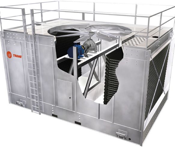
System Overview

               airside              chilled-          refrigeration     condenser-water              heat
                loop               water loop              loop              loop                  rejection
                                                                                                     loop

               supply              chilled-water                       condenser-water           cooling
                fan                    pump          compressor            pump                 tower fan

        indoor           cooling                                                          tower          outdoor
                                                evaporator     condenser
          air              coil                                                             fill           air

        zone sensor                 control            expansion             control            cooling
                                    valves               device              valves           tower pump

Components                                                     Flexible applications
The above graphic depicts five "loops" commonly used           Chilled-water systems can be designed to grow and adapt
in a chilled-water system to remove heat from zone             to building and load changes over time. Systems are often
or process loads. This system comprises one or more            sized to easily incorporate future cooling load expectations
chillers, cooling tower(s), condenser-water pumps, chilled-    and to recover heat. Cooling is distributed by water, which
water pumps, and load terminals served by control valves.      is a relatively benign substance compared to distributed
Fixed- or variable-speed compressors provide cooling,          refrigerant. Comfort and process cooling loads can share
while flow rates are optimized for a combination of            the same system.
efficiency and cost.
                                                               Scalable
Coordinated, integrated                                        Chilled-water systems are an excellent choice for large
The Tracer® Chiller Plant Control system controller uses       buildings, such as office towers, healthcare, higher
pre-engineered yet flexible control sequences to achieve       education, data centers and indoor agriculture. Expansion
high performing system operation. Routines include             is relatively easy when loads increase, or as interior spaces
staging, mode control, chiller-tower setpoint optimization,    are built out.
and trim-and-respond pump-pressure reset or chilled-
water temperature reset.                                       Centralized maintenance
                                                               Maintenance tasks are easier when they are centralized
                                                               and out of occupied spaces. Long-lived components mean
As the loads in the system change, variable-speed
                                                               fewer replacements over the course of a building’s life.
fans in the cooling tower are modulated to maintain
the tower sump at setpoint, while cooling is staged or         High performing
modulated to maintain the chilled-water temperature at         Water-cooled heat rejection is more effective than air-
setpoint. Load terminals such as cooling coils in central      cooled. Centralized equipment uses more efficient, larger
station air-handlers, area-level blower coils, zone-           motors.
level fan coils, or sensible-cooling terminals respond
to changes in the zone cooling loads by modulating             Simplified
chilled-water valves and by staging or modulating fans.        Chilled-water systems can be efficient by design, with easy
                                                               to understand controls.

4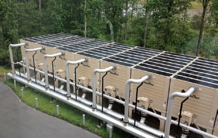
State-of-the-Art Design                                        ANSI/ASHRAE/IES Standard 90.1-2016, Energy
                                                               Standard for Buildings Except Low-Rise
A well-engineered system exploits the dramatic                 Residential Buildings
improvements in modern chiller efficiency to further
                                                               • 15°F + ΔT cooling coil selection, 57°F+ return1
improve overall system efficiency. By working the chiller
                                                               • 50% cooling tower water-flow turndown2
a little bit harder on the most challenging cooling days,
                                                               • Variable speed pumping for chilled water3
designing differently unlocks cost savings now, plus saves
                                                               • Pipe sizing4 and insulation5
energy. This is accomplished by reducing the water flow-
rates—on the chilled-water side and on the condenser-          ASHRAE Learning Institute, Fundamentals of
water side of the system. Savings are significant in many      Design and Control of Central Chilled-Water
cases, and not only affect the cooling system but also the     Plants, 2016
electrical system, building construction, site permitting
                                                               • 25°F ΔT chilled water starting point6
and power infrastructure.
                                                               • 15°F ΔT condenser water7

There is a truism that systems are typically oversized.        ASHRAE Advanced Energy Design Guides
Engineers are conservative. Most people interpret
                                                               • At least 15ºF ∆T chilled water (hospitals)8
this to mean that the HVAC equipment has too much
                                                               • 12-20ºF ∆T chilled water (K-12 schools)9
cooling and/or heating capacity. But what about the
                                                               • At least 14ºF ∆T condenser water
capacity of the rest of the system? “Rightsizing” doesn’t
just mean the equipment— it’s also the pipes, valves,          ASHRAE GreenGuide10
water volume, and building structure.
                                                               • 12-20°F ΔT chilled water
                                                               • 12-18°F ΔT condenser water
The techniques in this design guide allow you to have
either the lowest first cost, or the lowest energy cost,       CoolTools™ Chilled Water Plant Design and
or a combination of both first cost and energy savings.        Specification Guide, 200011
In some instances it’s possible to have both the lowest        • 15-18°F ΔT chilled water
first and the lowest energy cost.
                                                               Kelly and Chan, Optimizing Chilled Water Plants,
Design differently to save the project                         HPAC Engineering, 199912
When projects are over budget, redesigning flow rates
                                                               • 18°F ΔT chilled water
provides no-compromise opportunities to reduce cost.
                                                               • 14°F ΔT condenser water
•   When the budget demands it
•   When there is limited space or structural support
•   When electrical infrastructure can be downsized
                                                               1 ANSI/ASHRAE/IES, 2016. ASHRAE 90.1 Energy Standard for Buildings Except
•   When limited by existing elements in system expansions     Low-rise Residential Buildings. section 6.5.4.7, 100.
                                                               2 Ibid., section 6.5.5.4, 101.
Design differently to save energy                              3 Ibid., section 6.5.4.2, 98.
                                                               4 Ibid., section 6.5.4.6, 100.
System efficiency can be maximized when designs use            5 Ibid., section 6.4.1.1.3, 85.
optimized flow rates.                                          6 Taylor, Steven T., P.E. 2017. "Fundamentals of Design and Control of Central
                                                               Chilled-Water Plants", ASHRAE. 159-164.
• Keep larger pipes to further reduce connected kW and         7 Ibid., 164-167.
                                                               8 ASHRAE/IESNA/AIA/USGBC/USDOE. 2012. "50% Advanced Energy Design
  save more energy                                             Guide for Large Hospitals." HV35, 201.
• Reinvest reduced water weight structural savings in          9 ASHRAE/IESNA/AIA/USGBC/USDOE. 2014. "50% Advanced Energy Design
                                                               Guide for K-12 School Buildings." HV6, 172.
  other energy and reducing building components                10 Swift, John M., Jr. and Tom Lawrence, ed. 2012. "ASHRAE GREENGUIDE: The
                                                               Design, Construction, and Operation of Sustainable Buildings." ASHRAE.
• Arrange chillers in series counterflow to decrease chiller   11 Pacific Gas and Electric. 2000. "CoolToolsTM Chilled Water Plant Design and
  and system energy consumption                                Specification Guide." 4-26.
                                                               12 Kelly, D. and T. Chan. 1999. “Optimizing Chilled Water Plants.” Heating/Piping/
                                                               Air Conditioning (HPAC) Engineering. 71.

Industry Guidance on Design
                                                                                                                                               5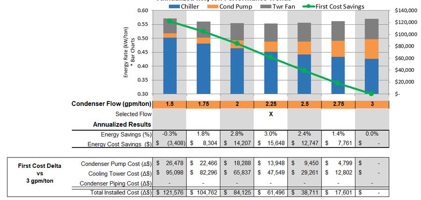
Selecting a Design Configuration

There are many choices about how to configure a chilled-               or dedicating the towers and pumps, winter operation
water system. Some may be limited by what is already                   and whether or not to dynamically vary the condenser
installed. However in many cases upgrades to existing                  pump flow This section explains the various pros
plants are necessary and present attractive opportunities              and cons to each of these choices, and the cost and
to reduce cost and energy consumption.                                 efficiency implications.

Besides picking a flow rate, typical choices on the                    One consideration when choosing is the pump energy
chilled-water side of the system include decoupled                     consumed by different configurations of chilled-water
versus variable-primary flow, parallel versus series                   systems.
chillers, as well as how to size and site bypass lines. On
the condenser-water side, choices include manifolding

Energy impact of plant configuration, turndown and flow rate on pumping energy

Pump energy impact of configuration                                    key benefit of varying flow through the chillers is that it
The color-paired performance groups above show annual                  allows the controls to delay starting a chiller when the
performance of constant flow, primary/secondary,                       operating chillers can handle increased flow. This delays
variable-primary flow and variable-primary/variable-                   the start of a cooling tower and condenser water pump
secondary flow systems. The left bar in the pair shows                 and may save system energy. A full-year comparison of
a traditional 10°F ΔT design. The right bar shows pump                 the entire system is advised when energy conservation is
energy consumed by these same configurations with a                    a key consideration for your project.
modern 15°F ΔT design. The energy impact of chillers
with less flow turndown is also shown.                                 The following pages provide descriptions and summaries
                                                                       of other aspects of common chilled- and condenser-water
This comparison solely considers the pump energy. The                  configurations. These are neither exhaustive explanations
energy consumed by the entire system will also vary                    nor comprehensive comparisons. Many other variations
between the various options and control strategies. A                  can be applied to address specific job needs.

6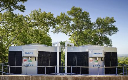
Chilled-Water Configuration: Decoupled (Classic Primary-Secondary)
Typical Applications
• Asymmetrical plants with
chillers of unequal size, vintage,
pressure drop
• Chillers without sufficient flow
chillers with dedicated, turndown capabilities
Alarm
Select Report Group Custom Chiller Refrigerant Compressor
Report Report Report Report
Select Settings Group Operator Service Service Diagnostics
Settings Settings Tests
Previous Enter Auto
Next Cancel Start
ADAPTIVE CONTROL
CENTRAVAC
SERIES R
constant flow pumps • Existing plants with sunk cost
in pumps and pipes, equipment
decoupler or bypass rooms that are difficult to
modify
• Systems without airside-
induced “low delta-T” syndrome
chilled-water variable-speed,
cooling coils secondary pump
This system configuration consists of one or more chillers, Disadvantages
often arranged in parallel with each other, with dedicated • More pumps mean more expense on new construction.
or manifolded chiller pump(s). A bypass pipe decouples the • Cannot compensate for chronic airside low chilled-water
operating pressures and flow of the chiller (primary) side ΔT.
from the building distribution (secondary) side of the system. • Constant chilled-water flow limits the use of extra
This allows for independent management of each chiller’s chiller capacity that may be available, for example when
and the distributed system flow. Chillers are added when relatively cool water enters the chiller condenser.
optimal for system operation or when the flow through the
Best practices
bypass goes “deficit”. That is, when the secondary flow
• Size the bypass pipe based on largest design flow of
exceeds primary flow and some return water mixes with
one chiller—not the distribution pipe diameter. It should
supply water, thereby raising the temperature going to the
be free of restrictions and about an equivalent length of
distribution system. The secondary pump speed is controlled
ten pipe diameters. The goal is to provide decoupling
based on a remote differential pressure or the valve positions
of pressure and flow while preventing the unintended
of the terminal devices, typically coils. Varying the secondary
mixing of supply and return chilled-water streams. A
pump(s) speed maintains the distribution system differential
check valve in the bypass is not desirable as it puts
pressure.
pumps in series which can make pump and chiller
Advantages control difficult.
• Relatively easy to expand—often a dedicated pump is • Match load and flow efficiently between primary and
installed per chiller and sized for its chiller’s flow and secondary loops with asymmetrical or “swing” chillers.
pressure drop. This neutralizes operating complexity within • Monitor critical valve positions at the cooling coils
plants with chillers of different age, size or pressure drop. serving air-handlers or fan-coils. Use trim-and-respond
• Accommodates asymmetry in chiller capacity, size, age, logic on either pump pressure setpoint or chilled water
and capabilities—allowing for system expansion and right setpoint.
sizing. • Select chiller for 2 to 4°F lower supply chilled-water
• System controls stage chillers on load, temperature or temperature than the cooling coils, to allow supply
flow. Chillers are added when there is not enough chiller temperature reduction compensation for airside low ΔT
capacity or flow to sustain secondary supply temperature, or increased system load.
a condition that can be simply sensed by temperature. • Install pressure-independent cooling coil control valves
Typically, there is no need for direct flow measurement. to preserve system capacity and minimize energy
• Simplest system operation and control—highest reliability consumption.
system. • Expect higher distribution system ΔT at part load.
Investigate if not.
7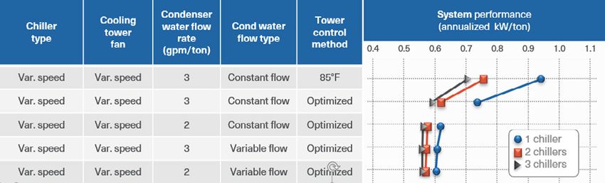
Chilled-Water Configuration: Variable-Primary Flow (VPF)

                             equal pressure drop
                             chillers with isolation
                                                                                       Typical Applications
                             valves
                                                                                        • Symmetrical plants with chillers
                                                                                           of equal size, capabilities and
                                                                                           pressure drop
           manifolded,                                                                  • Systems exhibiting an
           variable-speed                                                                  undesirable airside induced
           pumps
                                                                                           “low delta-T” syndrome
                                                                                        • Chillers with sufficient
                                                                                           flow turndown and control
                                                                                           capabilities
          minimum flow bypass with valve                                                • Retrofits for existing plants with
                                                                                           constant flow pumping and
                                                                                           VPF-suitable chillers
                                                 chilled-water
                                                 cooling coils

This system configuration consists of one or more                Best practices
chillers, often arranged in parallel with each other, with       • Select for equal or nearly equal pressure drop if chillers
manifolded pumps. A valve opens in a smaller bypass pipe           are in parallel. Flow and therefore load will divide equally
whenever system flow does not meet the chiller minimum.            across all operating chillers.
Chillers are added when the operating chiller(s) are no          • Minimize surplus flow and limit the need for bypass by
longer achieving the system setpoint temperature. The              selecting chillers with good flow turndown. Aim for at
system pumps’ speed is determined based on a remote                least a 2:1 chilled-water-flow turndown.
differential pressure or the valve positions of the terminal     • Identify chiller flow and rate-of-flow change limitations.
devices, typically coils.                                        • Size the bypass and bypass valve for the highest chiller
                                                                   minimum flow. Oversizing makes accurate and stable
Advantages                                                         control difficult.
• Costs less to install, typically costs less to operate         • Consider series chillers for reduced flow disruption
• Enables chillers to fully load                                   during sequencing. Although series chillers typically have
• Able to over-pump chillers to accommodate systems                higher pressure drop at design flow, pressure drop and
  with low ΔT                                                      energy reduce as the flow and load go down.
• Symmetry of chillers simplifies which chiller to operate,      • Select chillers and chiller options that automatically tune
  common parts and performance expectations                        the control response for higher and lower flow rates.
• System controls stage chillers on temperature and              • Monitor critical valve positions at the cooling coils
  compressor power, both reliable and repeatable                   serving air-handlers or fan-coils. Use trim-and-respond
  measurements, or based on measured tons                          logic on either pump pressure setpoint or chilled water
• No need for swing chillers to minimize surplus flow              setpoint.
Disadvantages                                                    • Work with a system controls vendor who has
• Chiller staging and controls are more complex                    demonstrated expertise with this system configuration.
• Bypass valve operation is critical for system reliability      • Commit to operator training and refresher courses about
• Selected chillers must have adequate flow turndown               system operating intent, sequences and limitations.
• Different size, flow or pressure drop chillers may make        • Install pressure-independent control valves to preserve
  reliable control and sequencing difficult or impossible          system capacity and minimize energy consumption.
• Airside low ΔT increases system pumping energy                 • Expect higher system ΔT at part load. Investigate if not.
  significantly
• Significant pump and pipe changes are required to
  retrofit from primary-secondary flow
• Chiller not universally suitable for this configuration

8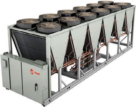
Chilled-Water Configuration: Variable-Primary, Variable-Secondary Flow (VPVS)
                                  equal pressure drop
                                  chillers with isolation
                                  valves                                                       Typical Applications
                                                                                               • Asymmetrical plants with chillers
                                                                                                  of unequal size, vintage, pressure
                      manifolded,                                                                 drop
                      variable-speed
                      pumps                                                                    • Systems exhibiting an undesirable
                                                                                                  “low delta-T” syndrome
                                                                                               • Chillers without significant flow
temperature
                                                                                                  turndown and controls capabilities
sensors for primary
pump speed control     decoupler bypass with no                                                • Retrofits for existing plants with
                       restrictions                                                               primary-secondary flow and
                                                                                                  variable-flow suitable chillers
                                chilled-water                  variable-speed,
                                cooling coils                 secondary pump

      This configuration combines the features of classic               Disadvantages
      primary/secondary and variable-primary-flow systems. It           • Higher first cost for new installations compared to
      consists of one or more chillers, often arranged in parallel        variable-primary-flow systems—more pumps and
      with each other. For existing primary-secondary system              associated electrical connections
      conversions, the existing bypass pipe can be used. For            Best practices
      new systems, the bypass pipe may be sized similar for the         • For new systems size the bypass pipe diameter based on
      minimum flow of the largest chiller in the system. In either        the largest chiller’s minimum flow (not distribution pipe
      case, the bypass has no restrictions in it.                         diameter), free of restrictions, with pressure drop equal
                                                                          ten pipe diameters’s worth of length. This decouples
      Add a chiller when the operating chillers no longer                 pressure and flow while preventing unintended mixing of
      achieve the system setpoint temperature, or earlier                 the supply and return chilled water streams.
      if it reduces system energy use. The primary pumps’               • With chillers in parallel, select for equal or nearly equal
      speed and flow creates a slight surplus flow. This can              pressure drop. Flow and load will divide equally across all
      be achieved using flow matching or using a return water             operating chillers.
      temperature difference before and after the bypass.               • Select chillers for a sufficient amount of chilled water
      Secondary pumps are controlled by remote differential               flow turndown. Aim for turndown to at least 80% of
      pressure.                                                           design. Less that that results in minimal pumping energy
                                                                          savings.
      Advantages
                                                                        • Select chillers and chiller options that automatically tune
      • Often results in the lowest overall system pumping
                                                                          the control response for higher and lower flow rates.
        energy, particularly with chillers that have limited flow
                                                                        • Use cooling coil valve positions and trim-and-respond
        turndown
                                                                          logic to reset distribution pump pressure setpoint and
      • Reduces system load versus chiller interaction,
                                                                          minimize pump energy. Raise setpoint when one or more
        improving system control dynamics and providing more
                                                                          valves are nearly wide open. Lower setpoint when no
        stable operation
                                                                          valves are nearly wide open.
      • More easily sequenced chillers, despite differences
                                                                        • Work with a system controls vendor who has
        in capacity, flow or pressure drop, than in other
                                                                          demonstrated expertise with this system configuration.
        arrangements
                                                                        • Commit to operator training and refresher courses about
      • May over-pump chillers to accommodate systems with
                                                                          system operating intent, sequences and limitations.
        low air-side ΔT
                                                                        • Install pressure-independent cooling coil control valves
      • Easier, faster and lower cost retrofit from a classic
                                                                          to preserve system capacity and minimize energy
        primary-secondary configuration—it doesn’t require
                                                                          consumption.
        piping changes—by adding VFDs to the primary pumps
                                                                        • Expect higher distribution system ΔT at part load.
        and modifying the control logic
                                                                          Investigate if not.
                                                                                                                                       9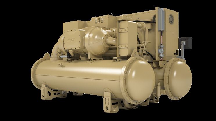
Chilled-Water Configuration: Series Chiller Evaporators with Parallel Condensers

                                                                                          Typical Applications
                                                                                          • Free cooling
                                                                                          • Heat recovery
                                                                                          • Variable-primary-flow systems
                                                                                          • Low flow systems (>15°F ΔT)
                                                                                          • Chillers with continuous
                                                                                            unloading compressors (such as
                                                                                            screw and centrifugal)
                        upstream compressor            downstream compressor
                                                                                          • Chillers with single-pass
                        does less work, uses less      does more work, uses                 evaporators
                        energy                         more energy

This system configuration consists of one or more chillers,        Best practices
arranged in series with each other on the chilled-water            • Free cooling on upstream chiller allows the free-
side of the system. Condensers are piped in parallel. When           cooling equipped chiller to see the warmest chilled
additional chillers are needed, series pairs are added in            water temperatures and the coldest condenser water
parallel with the first pair. Each set of chillers gets either a     temperatures. This increases the number of hours when
dedicated pump or an isolation valve.                                free cooling is advantageous. A chiller in this position
                                                                     is easier to preferentially load and it also means that
Advantages                                                           the cycle can continue uninterrupted by allowing the
• No flow disruptions during transitions (adding or                  downstream chiller to automatically pick up any load not
  subtracting a chiller) because flow is already going               satisfied by the upstream chiller.
  through both chillers before the transition                      • Heat recovery on downstream chiller with a parallel
• Upstream chiller can be equipped for onboard refrigerant           condenser circuit allows the chiller to adjust its
  migration free cooling while downstream chiller is set up          condensing pressure independently of the upstream
  for integrated mechanical mode or heat recovery.                   chiller. Condenser water is routed to the heating
• Variable primary flow reduces pump energy penalty at               loop either directly or indirectly through another heat
  lower load/lower flow conditions.                                  exchanger. Shed only the excess heat by adjusting
Disadvantages                                                        the upstream chiller capacity to leave the desired heat
• System energy not optimized (see series-counterflow)               rejection load for the downstream chiller. Upstream chiller
• Higher pump energy at design flow conditions, variable             could be in free- or mechanical-cooling mode, if equipped.
  flow can overcome at reduced load/flow                           • Size upstream chiller for achieving design system setpoint
• System ΔT must be maintained in order to load the                  at reduced flow. This allows the downstream chiller to be
  chillers                                                           taken offline for service while the upstream chiller makes
                                                                     the desired temperatures.
                                                                   • Consider service bypasses (not shown) around each of the
                                                                     chillers.

10
Chilled-Water Configuration: Series Chiller Evaporators and Series Condensers
Typical Applications
• District cooling with either large
tonnage and/or long distances
• Heat recovery
• Variable-primary-flow systems
• Low flow systems (>15°F ΔT)
• Chillers with continuous
unloading compressors (such as
screw and centrifugal)
upstream and downstream compressors do approximately equal
work due to thermodynamic staging, saving system energy • Chillers with single-pass
evaporators and single-pass
condensers
This system configuration consists of one or more chillers, Best practices
arranged in series with each other on the chilled-water • A minimum ΔT across both series chillers (especially for
side of the system. The condenser flow is also series, with those using plate heat exchangers) might be 14°F ΔT,
the flow running counter to the chilled-water flow. The while typical would be 18 to 20°F ΔT. Higher ΔTs (25°F+)
chiller receiving the warmest chilled water also receives are achievable with this configuration.
warmer condenser water. In this way, the work of the • Best efficiency is achieved when chillers are selected
chiller compressors is spread evenly across the plant— for the duty (i.e. upstream chiller is optimized for the
saving energy. Larger system ΔTs are typical so that intermediate water temperatures.) More redundancy is
chillers (especially those using plate heat exchangers) can achieved when the upstream chiller is capable of creating
stay below velocity limits. the final chilled water temperature with hotter condenser
water. Variable speed compressor(s), if available,
When additional chillers are needed, pairs are added eliminate the efficiency penalty of the less-than-optimal
in parallel. Each set of chillers gets either a dedicated compressor operating at the warmer setpoint.
pump or an isolation valve. • Consider service bypasses (not shown) around each of
the chillers.
Advantages
• Best system energy consumption by reduced compressor
lift, lowest flow rates and excellent flow turndown
• No flow disruptions during transitions (adding or
subtracting a chiller) because the flow is already going
through both chillers before the transition
• Reduced pump penalty with variable-primary flow at
lower load/lower flow conditions
Disadvantages
• Higher pressure drop leads to higher pump energy at
design flow conditions, variable flow can overcome this at
lower load/flow conditions
• System energy not optimized (see series-counterflow)
• System ΔT must be maintained in order to load the
chillers.
11Chillers Key Components
A• Evaporator heat exchanger
B E
B• Compressor
C• Condenser heat exchanger
A C
D• Expansion device
D E• Unit controller
In a water-cooled HVAC system, the chiller extracts heat applied climate zone, building type, plant size, number of
with a refrigerant that is selected and manipulated to chillers, tower control strategy and other factors. It can
"boil" at the temperature of the chilled-water or chilled- even create one based on a user-entered system load
fluid loop. This removes the latent heat of vaporization profile. The output provides suitable test conditions that
from the chilled-water loop. The compressor then represent common operating points for that chiller once
"pumps" this now vaporized refrigerant from a low installed.
pressure to a higher pressure. The condenser heat
exchanger then cools the refrigerant to the point where Approach is a measure of the effectiveness of a heat
it condenses back to a liquid, at a higher pressure, giving exchanger. Approach is the temperature difference
up the latent heat of fusion to the condenser-water between the refrigerant and the fluid. Changes in
loop. The high pressure refrigerant liquid is then sent approach over time at the same system conditions can
through an expansion device that lowers the pressure indicate the need for service.
of the liquid. The heat removed in the condenser is sent
to a heat sink, typically cooling towers (most common), Pressure drop is a measure of the waterside resistance
ground loops or heating systems. to flow. It is used directly during pump selection, but it is
indirectly a measure of where the design flow rate falls
Performance metrics in the range of flows of a given heat exchanger. Besides
Each chiller selection provides a lot of numbers. Some of the flow rate, it is affected by the number, type and
them are important for understading the performance of diameter of tubes in a shell-and-tube heat exchanger.
that particular chiller in a given system. In a brazed-plate heat exchanger, it is affected by the
number of plates, channels and sizes of the channels. A
Efficiency measures the amount of cooling effect that slightly higher pressure drop, particularly in a shell-and-
is delivered versus the amount of energy required to tube heat exchanger, is usually an indication that the
do it. For water-cooled chillers, common units are kW/ heat exchanger has a good flow-rate turndown.
ton and coefficient of performance, COP. For proper
electrical sizing and energy code compliance, full- Turndown characterizes the chiller's ability to operate
load efficiency is a key efficiency metric. For code with less than the design flow rates, in both the
compliance, there is also a part-load efficiency metric evaporator and condenser. Turndown is essential when
(IPLV or NPLV), depending on the design conditions. selecting chillers for variable-flow-rate applications.
We use IPLV for standard design conditions (and
always for positive displacement chillers) and NPLV Amps, both for running and starting are helpful, as
for non-standard design conditions for centrifugal are other electrical metrics such as minimum circuit
chillers. For evaluation of one chiller versus another, ampacity (MCA) and maximum overcurrent protection
Trane created myPLV®—a metric that adjusts for the (MOCP), for electrical system and component sizing.
12Chiller Variations
Sound, footprint, efficiency and capacity are key factors
that differentiate one chiller style from another. Each chiller
platform has advantages in one or more of these criteria.
Centrifugal chillers use a compressor that develops pressure
by converting velocity to static pressure. Refrigerant is
collected by an impeller rotating on a shaft, then channeled
Centrifugal compressor
through a channel called a volute to convert the energy of
rotation into potential energy. The pressure that results must
be higher than the condensing pressure in order for this
device to work. The exit refrigerant pressure is a function of
the refrigerant, the impeller diameter and the speed, as well
as the geometry of the volute.
Positive displacement chillers use a compressor that
captures a volume of refrigerant and squeezes it into
smaller chambers to increase its pressure. Typical modern
Screw compressor
chillers of this type use either helical-rotary "screw" or scroll
compressors. These types of chillers are often smaller and
are well suited to higher condensing pressure applications
such as thermal storage, heating and air-cooled condensing.
Variable speed devices may be applied to all three types of
compressors: centrifugal, screw and scroll. These take the
place of a traditional starter. Their purpose is to change the
speed of the compressor motor in response to changes in
the pressures in the evaporator and condenser, and to a
Scroll compressor
lesser degree, the amount of cooling desired. When properly
applied, variable-speed devices save energy.
Heat exchanger types
Shell-and-tube heat exchangers have a vessel - the shell -
with tubes inserted inside. The refrigerant can be outside
of the tubes (flooded) or inside the tubes (direct-expansion.)
Distributing the refrigerant and enhancing the tube surfaces,
so that the refrigerant molecules interact efficiently with the
Shell-and-tube heat exchanger
fluid on the other side of the tubes, while changing phase, is
the focus of a lot of engineering. This type of heat exchanger
has a wide flow-rate application range.
Brazed-Plate Heat Exchangers (BPHE) create areas where
refrigerant and liquids exchange energy by welding (brazing)
plates together to form channels. Their primary advantage
over shell-and-tube is compact size. The range of flow rates
is more limited and this type is used most often on smaller,
packaged and less customizable chillers.
Brazed-plate heat exchanger
Image courtesy of SWEP
13Chiller Application Considerations
F System Design Order of Operation
In many ways, the chiller should be the last thing in
the chilled water system to be selected. Virtually all
ASHRAE's Fundamentals of Design and Control of
other elements impact the chillers, and some chillers
Central Chilled-Water Plants suggests starting with coil
will be more suited than others for the intended
and tower selections to derive, rather than select system
application. This is a significant paradigm shift from
temperatures and flow rates, then proceed to chiller
business as usual. Because it's so unusual to think
selection. Sometimes existing systems present immovable
this way, this catalog should be reordered to start with
design limitations, though it's important to evaluate
the coil selections.
whether this is true before accepting any impediments to
advancing the system design.
Performance Testing
Factory performance tests confirm that your chiller’s
actual performance matches what was predicted during
the selection process before the chiller is installed on
site.
Standard AHRI tests are a well-recognized industry
practice, performed by all chiller manufacturers.
However, a chiller’s operating conditions vary
significantly based on the needs of the building and
its occupants. Data centers, hospitals and retail
myPLV tool assists with design choices and performance conditions
locations all have specific requirements unique to their
application and location. With today’s evolving HVAC building model data, calculating four performance points
system designs and customers’ diverse performance (94, 75, 50 and 25 percent) based on the specific building
expectations, standard AHRI tests are often no longer type, location and plant design, providing accurate
sufficient to accurately confirm that a chiller will weighting points and condenser temperatures. The myPLV
operate as required. tool also calculates the ton-hours at each of those points
necessary to accurately estimate annualized energy use.
That’s why Trane designed and built industry-leading
testing facilities, capable of evaluating performance Utilizing the myPLV tool from the beginning assures
based on customer-defined parameters including that the selected chiller is appropriate for the particular
building type and geographical location. Before the application. Then, myTest certification confirms the chiller
chiller leaves the factory, the new Trane myTest™ performs as expected. More about myPLV online here.
program validates chiller performance under the
conditions at which it should operate once installed. AHRI 575 sound tests can also be performed in the factory.
AHRI or myPLV® Verification F
"Performance testing of systems is essential to
Verifying chiller performance in real-world conditions ensure that all the commissioned systems are
is at the core of Trane testing capabilities. Accurate functioning properly in all modes of operation. That
performance starts at the design stage by calculating is a prerequisite for the owner to realize the energy
the appropriate myPLV rating points. The manufacturer- savings that can be expected from the strategies and
agnostic myPLV tool leverages industry-standard recommendations contained in this Guide."
14 --Advanced Energy Design Guide, ASHRAE 2009Air- versus Water-Cooled First, installed cost. A comprehensive review of the
The choice between air- and water-cooled chillers overall first costs must be done for each project,
generally comes down to several factors, such as including equipment, site preparation, installation and
operator sophistication, cooling tons, site constraints commissioning.
(such as space, water scarcity, acoustics or climate), first
cost and life-cycle cost. Life-cycle cost. Air-cooled systems are exposed to
the elements and typically don’t last as long as water
Operator sophistication and availability. Air-cooled cooled systems do. Air cooled systems don’t carry
systems can be easier to operate, due to the simple water treatment costs and chemicals. There is no
fact that there are fewer components. Is a trained cooling tower to winterize. System efficiency is lower in
operator available? Comprehensive system controls air-cooled systems than water cooled, though thermal
can equalize most of the perceived difference in storage can perhaps make up the difference.
complexity. However, operators need to be onsite
to inspect elements like cooling towers operating in Only a comprehensive full-year analysis that includes
winter. installed costs, energy and water, maintenance and
replacement costs can determine the true total cost of
System size. Any chiller that ships assembled is ownership for a given system.
limited by the size of the equipment that transports it.
annual maintenance
While the largest water-cooled chiller that ships fully water -- cooling system
mid peak demand
assembled might provide 3500 tons of cooling, the
$410,000 on peak demand
mid-peak consump�on
largest air-cooled chiller provides less than 600 tons.
off peak consump�on
$360,000 on peak consump�on
$46,467
$43,541
$47,305
Site constaints. Air-cooled chillers are installed
$310,000 $45,386
$43,501 $42,953
$88,689
outdoors, while water-cooled chillers are almost $260,000 $85,277
$83,606
$80,063
always indoors with cooling towers outdoors. What $70,942 $69,052
kind of space is available for the system? Is the
$210,000
water quality and availability good for water-cooled
$108,890
$96,695 $97,657
$160,000 $94,788 $94,751 $96,829
equipment? Is the air-cooled equipment sound or the
cooling tower plume objectionable to the neighbors? $110,000
$52,865
$48,669
$48,653 $48,658 $55,524
$54,531
Is it a cold climate application where the operating $60,000
hours are low? Is the air quality suitable for outdoor $72,851 $64,279 $68,948 $62,048 $55,579 $56,637
equipment? Tree seeds, pollens, poor air quality or $10,000
90.1 Baseline Conven�onal Comprehensive Comprehensive Comprehensive Comprehensive
proximity to the ocean can impact outdoor equipment Water Cooled Water Cooled Air Cooled Water Cooled WC with Ice AC with Ice
performance and life expectancy. $13.92/�2
$10,325,891
$12.68/�2 $10.52/�2 $11.42/�2 $11.35/�2 $10.98/�2 cooling installed cos
$9,402,723 $8,709,196 $8,879,988 $8,594,794 $8,405,565 20-year life cycle co
Refrigerant Selection
The industry continues to work through global and The entire CenTraVac® chiller portfolio has earned
national associations to engage with non-governmental third-party verification with a product-specific Type III
organizations (NGOs) and governments to ensure that Environmental Product Declaration (EPD), confirming
we transition away from high-GWP refrigerants in a way that its environmental impacts are the lowest in the
that is technically feasible, safe, and allows for servicing water-cooled chiller industry.
of existing equipment to ensure a useful life from
equipment investments.
Trane offers chillers today in various sizes and types
that feature low Global Warming Potential refrigerants.
Chillers with this option carry the EcoWise® designation.
15Air-Cooled Chillers
Air-cooled chillers have the advantage of including
the entire condensing system in the same package
that also chills the water. Optimizations on refrigerant
temperatures, fan speed, compressor speed and staging
are all accomplished in the on-board unit controller. This
control over the larger portion of the system recovers some
of the efficiency lost by the higher condensing pressures
experienced in air-cooled systems. In addition, air-cooled
chillers consume no water. Cooling capacities in packaged
air-cooled chillers are limited by transportation. Modular
arrangements are assembled onsite to increase air-cooled
capacities and resolve installation constraints or costs.
Because of their higher temperature capabilities and
better efficiency improvement at night, air-cooled chillers
are ideal candidates for Thermal Battery™ energy
storage systems.
Sound, footprint, efficiency, capacity, installation,
service considerations and price are key factors that
differentiate one chiller from another. Each chiller
platform has advantages in one or more of these criteria.
Trane provides interactive selection programs through For more information
Trane Select Assist software available online.
Air-cooled chiller portfolio at trane.com
16Air-Cooled Chiller Selection Considerations
System Configuration and Size Chilled Water Temps and Flows Condensing Temps
How big and how it's configured Temperatures on the chilled water Temperatures on the condenser side
drive a lot of choices. For example, side are an output of the coil and are determined by the location (design
variable flow through the evaporator airside selections. By starting with a drybulb temperature) and whether or
determines, through flow turndown, specific temperature or ΔT in mind, not the unit will be used for heating.
whether air-cooled chillers make system optimizations may be left Partial or full heat recovery, and
sense (or if variable flow makes behind. This catalog gives guidance reversible heat pumps are available
sense), or if asymmetry is a help or on how to select coils for best variations of standard air-cooled
a hindrance. See previous section operation at design and off-design chillers.
for more information on how system conditions.
configuration impacts chiller selection
and vice versa.
Water Quality, Fouling, Fluid Type Energy Storage Efficiency and Price
The water or fluid to be used in the If the chiller will be used now or Besides the many other
system impacts the tubes used in a in the future as part of an energy considerations, sometimes it all
shell-and-tube heat exchangers, flow storage system—whether water comes down to a decision on the
switch settings, the amount of freeze or ice storage—minor machine right balance of efficiency and price.
and burst protection in cold climates, changes may be necessary at the Trane has tools to help discover the
limits and safeties, as well as capacity time of selection, and may impact the value that each selection offers—from
and efficiency. suitability of a particular chiller for the spreadsheet-based tool myPLV® to
energy storage application. TRACE® 3D Plus full-year, whole-
building energy and economic
simulation.
17Water-Cooled Chillers
Water-cooled chillers have several advantages, including
the flexibility to site chillers and heat rejection in different
locations. Optimizations occur within a system controller
programmed to accommodate the specifics of the
application -- the types and quantities of chillers, pumps,
and cooling towers for example. Because rejected heat
is entrained in water, it can be easier to divert to heating
systems. Comprehensive designs create robust systems that
do not rely too heavily on system controls to avoid limiting
conditions while still delivering state-of-the-art performance.
The Trane® water-cooled chiller portfolio includes
centrifugal, helical rotary and scroll compressor
models, ranging in capacities from 20 to over 4,000
tons. Regardless of the chiller you choose, you’ll benefit
from the exceptional efficiency coupled with reliable
performance that has made Trane chillers the industry
standard for decades.
Sound, footprint, efficiency, capacity and price are key
factors that differentiate one chiller style from another.
Each chiller platform has advantages in one or more
of these criteria. Trane provides interactive selection
For more information
programs through Trane Select Assist software available
Manhattan
from
Gen II www.traneselectassist.com. Water-cooled chiller portfolio at trane.com
Scroll compressor, R-410A, heat recovery and four-pipe reversible heat pump with free cooling and variable speed options
SuperMod™ VSD scroll compressor, R-410A four-pipe reversible heat pump with free cooling option
MiniMod™ Magnetic-bearing, variable-speed centrifugal compressor, R-134a or R-513A, oil-free
PolyTherm Scroll compressor, R-410A six-pipe reversible simultaneous heating and cooling
RTWD Screw compressor, R-134a or R-513A non-reversible heat-pump heating with thermal battery option
Series R®
Variable-speed screw compressor, R-134a or R-513A
Optimus® non-reversible heat-pump heating with thermal battery option
TACW Magnetic-bearing, variable-speed centrifugal compressor, R-134a or R-513A, oil-free non-reversible heat pump
Magnetic-bearing, variable-speed centrifugal compressor,
Agility® R-134a or R-513A, oil-free, non-reversible heat-pump heating
Centrifugal compressor, R-514A or R-1233zd, non-reversible heat-pump heating,
CenTraVac® variable speed, six-pipe simultaneous heating and cooling, integral free cooling and thermal battery options
Centrifugal compressor,
Duplex® non-reversible heat-pump heating with variable speed and thermal battery options R-514A or R-1233zd
18Water-Cooled Chiller Selection Considerations
System Configuration and Size Chilled Water Temps and Flows Condensing Temps and Flows
How big and how it's configured Temperatures on the chilled water Temperatures on the condenser
drive a lot of choices. For example, side are an output of the coil and side are determined by the location
variable flow through the evaporator airside selections. By starting with a (design wetbulb temperature), tower
determines, through flow turndown, specific temperature or ΔT in mind, selection and limitations, and by
whether packaged or configured system optimizations may be left condenser water flow optimization.
chillers make sense (or if variable behind. This catalog gives guidance See the condenser flow optimization
flow makes sense), or if asymmetry is on how to select coils for best section for more on this topic. If the
a help or a hindrance. See previous operation at design and off-design system will recover condenser heat,
section for more information on how conditions. what is the desired temperature?
system configuration impacts chiller
selection.
Water Quality, Fouling, Fluid Type Energy Storage Efficiency and Price
The water or fluid to be used in the If the chiller will be used now or Besides the many other
system impacts the tubes used in in the future as part of an energy considerations, sometimes it all
a shell-and-tube heat exchangers, storage system—whether water or comes down to a decision on the
needed compressor capabilities, ice storage—minor or major machine right balance of efficiency and price.
motor selections as well as heat changes may be necessary at the time Trane has tools to help discover the
exchanger options such as tube of selection, especially for centrifugal value that each selection offers—from
cleaning systems, coatings, sacrificial chillers. Most Trane chillers support spreadsheet-based tool myPLV® to
anodes and other options. both types of energy storage. TRACE® 3D Plus full-year, whole-
building energy and economic
simulation.
19Condenser-Water Flow Rate Optimization Typical Applications
• New projects
Design flow-rate considerations
• Chillers being replaced
The decision on an optimum flow rate to use for the • Towers being replaced
condenser water loop can be evaluated using the flow • Expanded capacity needed
optimization portion of myPLV. It can solve for best • Energy conservation
efficiency, best cost, or a combination of efficiency and
cost advantages.
First cost and operating cost benefits are maximized
Best efficiency may be achieved by leaving the cooling
when the cooling tower and condenser water pump are
tower and condenser water pipes sized for 3 gpm/ton,
right-sized but the condenser pipes are kept large. In
but operated at something lower. This entails selecting
many cases, there is little to no energy impact of these
a chiller that is capable of creating slightly different
changes. In fact, a right-sized cooling tower often leads
condensing pressures. The optimium flow rate will vary
to lower overall system energy consumption.
based on the application, climate zone, load profile, etc.
The first cost benefits are not trivial. Consider all
Lowest installed costs are achieved when the cooling
aspects of the system cost, such as roof space and
tower, condenser water pump and condenser pipes
reinforcement, electrical savings, pipe costs and
are downsized. The impact on peak and annual energy
structural support differences, and more.
use may be minimal and can be quantified in the flow
optimization calculation.
For more information
Video on condenser-water flow optimization
myPLV condenser-water flow-rate optimization — balanced first and energy cost option
20Variable Condenser-Water Flow
Typical Applications
Using system controls to optimize energy • Existing plants
• Single chiller plants
In existing plants, chiller capabilities may make it
• Little to no equipment changes
difficult to operate the plant with ASHRAE GreenGuide-
• Control upgrades needed
recommended condenser-water flow rates. In cases like
• Systems with high condenser
these and without chiller replacement(s) planned, it can
water flow (3 gpm/ton+)
be beneficial to turn the system into one that uses a lower
• Energy conservation
flow rate some of the time, and a higher flow rate at other
times. This strategy is commonly referred to as variable
condenser-water flow.
Trane controls can be configured to adjust cooling
tower fan speed, condenser-water pump speed and
chiller speed simultaneously. Many limit conditions Best practices
must be determined and programmed into the system. • Use the ASHRAE GreenGuide's suggestion of 12 to 18°F
These include: chiller surge and water flow-rate limits, ΔT for condenser-water systems (2.3 to 1.6 gpm/ton) to
condenser pump limits, tower flow rate limits. In most reduce plant installed and life-cycle costs.
cases, a very small throttling range for the condenser • Consider varying cooling tower fan speeds in all
pump results in the most efficient operating point. installations.
• Consider varying condenser-water pump and cooling
The chart below shows the efficiency benefit of tower fan speeds on systems not designed using the
implementing variable flow when ASHRAE GreenGuide ASHRAE GreenGuide guidance, and where the plant
flow rates are not an option. In all cases, an optimized operators are on board, training and retrained when the
cooling tower temperature setpoint made a big operators change. When used, keep the control method
difference in energy. The variable flow (second from understandable, transparent and as simple as possible
bottom row) had nearly identical energy use as the (but not simpler.)
GreenGuide-informed, constant flow rate design (middle
For more information
row.) Variable flow on the GreenGuide design showed
virtually no benefit on systems with two or more chillers. Engineers Newsletter Live available online
Annualized energy consumption of GreenGuide-informed condenser-water flow-rates versus dynamically variable flow rates
21You can also read