CAR 2 CAR Communication Consortium Manifesto
←
→
Page content transcription
If your browser does not render page correctly, please read the page content below
CAR 2 CAR Communication Consortium

                           Manifesto

              Overview of the C2C-CC System

__________________________________________________

Report name                                      C2C-CC Manifesto

          This document summarizes the main building blocks for a
                       CAR 2 X Communication System
       as it is pursued by the CAR 2 CAR Communication Consortium.

                               C2C-CC System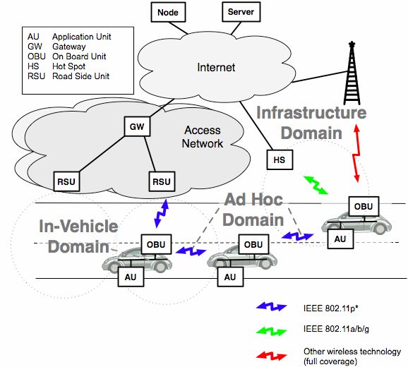
.              C2C-CC Manifesto                Page 2
C2C-CC

Document status                                                        Public

Version number                                                  Version 1.1

Date of release                                           28th August, 2007
by the Technical Committee

                             Version    Date                     Number of page

                             1.1        August 28, 2007                2/94
.                   C2C-CC Manifesto                              Page 3
C2C-CC

Revision Chart and History Log

Releases:

Version     Changes                                  Editor                     Date of            New
                                                                                TC-Release         Version
            First release                            See list of contributors   21st May 2007      1.0
                                                     in this document
            Notation of CAR 2 CAR, CAR 2 X, etc.     Heyms                      28th August 2007   1.1

                                               Version        Date                              Number of page

                                               1.1            August 28, 2007                         3/94
.                        C2C-CC Manifesto                                            Page 4
C2C-CC

Table of Contents

1    Introduction ............................................................................................................. 9

    1.1     About This Document...................................................................................................................9
    1.2     CAR 2 CAR Communication Consortium ...................................................................................9
    1.3     C2C-CC Demonstration Event in 2008 ......................................................................................10
    1.4     Conventions and Terms .............................................................................................................11

2    Scenarios ............................................................................................................... 12

    2.1     Safety        .......................................................................................................................................12
          2.1.1           Cooperative Forward Collision Warning ........................................................................13
          2.1.2           Pre-Crash Sensing/Warning ..........................................................................................13
          2.1.3           Hazardous Location V2V Notification ............................................................................14
    2.2     Traffic Efficiency .........................................................................................................................14
          2.2.1           Enhanced Route Guidance and Navigation ..................................................................15
          2.2.2           Green Light Optimal Speed Advisory ............................................................................15
          2.2.3           V2V Merging Assistance................................................................................................16
    2.3     Infotainment and Others.............................................................................................................16
          2.3.1           Internet Access in Vehicle .............................................................................................16
          2.3.2           Point of Interest Notification...........................................................................................17
          2.3.3           Remote Diagnostics.......................................................................................................17

3    System Prerequisites and Constraints ............................................................... 19

    3.1     Economical Prerequisites and Constraints..............................................................................19
    3.2     Technical Prerequisites and Constraints .................................................................................21
          3.2.1           Anonymity and Data Security ........................................................................................21
          3.2.2           Effective Protected Frequency Band .............................................................................21
          3.2.3           Scalability.......................................................................................................................22
          3.2.4           Mandatory Sensor Data.................................................................................................23

4    System Architecture ............................................................................................. 25

    4.1     System Overview ........................................................................................................................25
    4.2     Basic Communication Principles ..............................................................................................28
    4.3     Architecture Perspective of Individual Components ..............................................................29
          4.3.1           Application Units ............................................................................................................29
          4.3.2           On-Board Unit (OBU).....................................................................................................30
          4.3.3           Road-Side Unit (RSU) ...................................................................................................31

                                                                      Version        Date                                            Number of page

                                                                      1.1            August 28, 2007                                          4/94
. C2C-CC Manifesto Page 5
C2C-CC
4.3.4 Entities Outside the Scope of the CAR 2 CAR Communication Consortium ................32
4.4 Layers’ Architecture and Related Protocols ............................................................................33
4.4.1 C2C Communication Application Layer.........................................................................34
4.4.2 C2C Communication Network Layer .............................................................................35
4.4.3 MAC/LLC Layer .............................................................................................................36
4.4.4 Physical Layer ...............................................................................................................37
5 Applications........................................................................................................... 38
5.1 Vehicle 2 Vehicle Cooperative Awareness ...............................................................................39
5.1.1 Application Instances.....................................................................................................39
5.1.2 Sender ...........................................................................................................................40
5.1.3 Receiver.........................................................................................................................40
5.1.4 Vehicle Systems ............................................................................................................40
5.1.5 Messages.......................................................................................................................40
5.1.6 Example .........................................................................................................................40
5.1.7 Use Cases .....................................................................................................................40
5.2 Vehicle 2 Vehicle Unicast Exchange.........................................................................................41
5.2.1 Application Instances.....................................................................................................42
5.2.2 Initiator ...........................................................................................................................42
5.2.3 Responder .....................................................................................................................42
5.2.4 Vehicle System ..............................................................................................................43
5.2.5 Messages.......................................................................................................................43
5.2.6 Example .........................................................................................................................43
5.2.7 Use Cases .....................................................................................................................44
5.3 Vehicle 2 Vehicle Decentralized Environmental Notification .................................................44
5.3.1 Application Instances.....................................................................................................46
5.3.2 Detector .........................................................................................................................46
5.3.3 Sender ...........................................................................................................................46
5.3.4 Receiver.........................................................................................................................47
5.3.5 Message Management ..................................................................................................47
5.3.6 Vehicle System ..............................................................................................................47
5.3.7 Messages.......................................................................................................................47
5.3.8 Example .........................................................................................................................48
5.3.9 Use Cases .....................................................................................................................49
5.4 Infrastructure 2 Vehicle (one-way) ............................................................................................49
5.4.1 Application Instances.....................................................................................................50
5.4.2 RSU System ..................................................................................................................50
5.4.3 Sender ...........................................................................................................................50
5.4.4 Receiver.........................................................................................................................50
5.4.5 Vehicle System ..............................................................................................................51
5.4.6 Messages.......................................................................................................................51
5.4.7 Example .........................................................................................................................51
5.4.8 Use Cases .....................................................................................................................51
5.5 Local RSU Connection ...............................................................................................................52
5.5.1 Application Instances.....................................................................................................52
5.5.2 RSU System ..................................................................................................................52
Version Date Number of page
1.1 August 28, 2007 5/94. C2C-CC Manifesto Page 6
C2C-CC
5.5.3 Sender ...........................................................................................................................52
5.5.4 Receiver.........................................................................................................................53
5.5.5 Vehicle System ..............................................................................................................53
5.5.6 Messages.......................................................................................................................53
5.5.7 Example .........................................................................................................................53
5.5.8 Use Cases .....................................................................................................................54
5.6 Internet Protocol Roadside Unit Connection ...........................................................................55
5.6.1 Application Instances.....................................................................................................55
5.6.2 RSU Router....................................................................................................................55
5.6.3 Client..............................................................................................................................55
5.6.4 Server ............................................................................................................................56
5.6.5 Vehicle System ..............................................................................................................56
5.6.6 Messages.......................................................................................................................56
5.6.7 Examples .......................................................................................................................56
5.6.8 Use Cases .....................................................................................................................57
6 Radio System ........................................................................................................ 58
6.1 General .......................................................................................................................................58
6.2 Application Categories ...............................................................................................................58
6.3 Physical Layer .............................................................................................................................59
6.3.1 Frequency Band ............................................................................................................59
6.3.2 Maximum Transmit Power .............................................................................................60
6.3.3 Transmit Power Control .................................................................................................60
6.3.4 Data Rates .....................................................................................................................60
6.3.5 Antenna..........................................................................................................................60
6.3.6 Communication Mode and Frequency Modulation ........................................................60
6.4 MAC/LLC Layer ...........................................................................................................................61
6.4.1 Multi Channel Operation ................................................................................................61
6.4.2 Dual Receiver Concept..................................................................................................61
6.4.3 Addresses ......................................................................................................................62
6.4.4 Maximum Message Size, Priorities and Waiting Times ................................................63
6.4.5 Logical Link Control .......................................................................................................63
7 Communication System ....................................................................................... 64
7.1 General Overview........................................................................................................................64
7.2 Design Principles ........................................................................................................................67
7.2.1 Geographical Addressing ..............................................................................................67
7.2.2 Forwarding Algorithms...................................................................................................67
7.2.3 Transport and Congestion Control ................................................................................69
7.3 Protocol Design...........................................................................................................................74
7.3.1 Network Layer Protocol .................................................................................................74
7.3.2 Transport Layer Protocol ...............................................................................................76
7.3.3 TCP/IP Protocol Integration ...........................................................................................78
Version Date Number of page
1.1 August 28, 2007 6/94. C2C-CC Manifesto Page 7
C2C-CC
7.4 Outlook .......................................................................................................................................79
8 Data Security and Privacy .................................................................................... 81
9 Summary and Conclusions .................................................................................. 85
10 Appendix................................................................................................................ 87
10.1 Terms and Definitions ................................................................................................................87
11 Contributors .......................................................................................................... 91
12 References............................................................................................................. 93
Version Date Number of page
1.1 August 28, 2007 7/94. C2C-CC Manifesto Page 8
C2C-CC
List of Figures
Figure 1 The system requirements are derived from various use cases .................................................. 12
Figure 2 Requested frequencies in Europe (taken from ETSI TR 102 492-2) ........................................ 22
Figure 3 Draft reference architecture.............................................................................................................. 27
Figure 4: Draft reference model ...................................................................................................................... 28
Figure 5 A RSU extends the communication range of OBU by forwarding of data................................. 32
Figure 6 A RSU acts as information source .................................................................................................. 32
Figure 7 A RSU provides Internet access...................................................................................................... 32
Figure 8 Protocol architecture of the C2C Communication System .......................................................... 33
Figure 9 Application Instances for Vehicle 2 Vehicle Cooperative Awareness........................................ 39
Figure 10 Application instances Vehicle 2 Vehicle Unicast Exchange...................................................... 42
Figure 11 Application instances for Vehicle 2 Vehicle Decentralized Environmental Notification......... 46
Figure 12 Application instances for Infrastructure 2 Vehicle (one-way) .................................................... 50
Figure 13 Application instances for Local RSU Connection ....................................................................... 52
Figure 14 Application instances for Internet protocol Road Side Unit connection................................... 56
Figure 15 Dual receiver concept ..................................................................................................................... 62
Figure 16 Geographic unicast ......................................................................................................................... 68
Figure 17 Topologically-scoped broadcast (example with scope = hops = 2) ......................................... 68
Figure 18 Geographically-scoped broadcast ................................................................................................ 68
Figure 19 Geographically-scoped broadcast with packet transport towards the target area................. 69
Figure 20 Main components of the C2C-CC network layer protocol ......................................................... 76
Figure 21 Security discussion areas............................................................................................................... 82
List of Tables
Table 1 C2C-CC Basic Application instance requirements for vehicles............................................ 38
Table 2 General capabilities for V2V Cooperative Awareness ............................................................. 39
Table 3 General capabilities for V2V Unicast Exchange........................................................................ 41
Table 4 General capabilities for V2V Decentralized Environmental Notification............................. 45
Table 5 General capabilities for Infrastructure 2 Vehicle (one-way)................................................... 49
Table 6 General capabilities for Local RSU Connection........................................................................ 52
Table 7 General requirements for Internet Protocol RSU Connection............................................... 55
Version Date Number of page
1.1 August 28, 2007 8/94. C2C-CC Manifesto Page 9
C2C-CC
1 Introduction
1.1 About This Document
This document summarizes and describes the main building blocks of the CAR 2 X Communication
System as it is pursued by the CAR 2 CAR Communication Consortium (C2C-CC). “CAR 2 X” means
interactions among cars, between cars and infrastructures, and viceversa. It provides interested
readers with an introduction to CAR 2 X communications. It is intended to be a living document which
will be complemented according to the progress of the work of the C2C-CC. One main objective of this
document is to give insight into ongoing and upcoming activities, such as public funded projects which
target to contribute to the C2C-CC specifications, an overview on ongoing work and results achieved
so far. In addition, this document provides concepts and technologies that have been developed or
identified by the C2C-CC and assessed as necessary building blocks to be proposed for a standard.
1.2 CAR 2 CAR Communication Consortium
The goal of the CAR 2 CAR Communication Consortium is to standardize interfaces and protocols of
wireless communications between vehicles and their environment in order to make the vehicles of
different manufacturers interoperable and also enable them to communicate with road-side units.
The mission and the objectives of the CAR 2 CAR Communication Consortium are
to create and establish an open European (possibly worldwide) industry standard for
CAR 2 CAR Communication Systems
to guarantee inter-vehicle operability
to enable the development of active safety applications by specifying, prototyping and
demonstrating the CAR 2 CAR system
to promote the allocation of a royalty free European-wide exclusive frequency band for CAR 2
CAR applications
to push the harmonization of CAR 2 CAR Communication standards worldwide
to develop deployment strategies and business models to speed-up the market penetration
The CAR 2 CAR system shall provide the following top level features:
automatic fast data transmission between vehicles and between vehicles and road side units
Version Date Number of page
1.1 August 28, 2007 9/94. C2C-CC Manifesto Page 10
C2C-CC
transmission of traffic information, hazard warnings and entertainment data
support of ad hoc CAR 2 CAR Communications without need of a pre-installed network
infrastructure
the CAR 2 CAR system is based on short range Wireless LAN technology and free of
transmission costs
Ad hoc CAR 2 CAR Communications enable the cooperation of vehicles by linking individual
information distributed among multiple vehicles. The so-formed Vehicular Adhoc Network (VANET)
works like a new ‘sensor‘ increasing the drivers’ range of awareness to spots which both the driver
and onboard sensor systems otherwise cannot see.
The CAR 2 CAR system electronically extends the driver's horizon and enables entirely new safety
functions. CAR 2 CAR Communications form a well suited basis for decentralized active safety
applications and therefore will reduce accidents and their severity. Besides active safety functions, it
includes active traffic management applications and helps to improve traffic flow.1
1.3 C2C-CC Demonstration Event in 2008
The C2C-CC plans to host a major demonstration event in late 2008. This event represents an
opportunity for research projects and individual companies to exhibit their achievements towards
politics, potential customers and general public. In detail, this event is intended to publicly demonstrate
beneficial use cases,
project interoperability,
functionalities, and
technical issues
of different European and national projects dealing with Vehicle 2 Vehicle (V2V or C2C) and Vehicle 2
Infrastructure (V2I or C2I) communications (collectively “C2X Communications”). The demonstration
will also show that the different technical concepts for C2X Communication developed in Europe
converge and can be harmonized in a European standard (or better worldwide standard) within a
reasonable timeframe.
1 Note that the term “CAR 2 CAR Communication” in the context of the C2C-CC always includes
“CAR 2 Infrastructure Communication”. The latter refers to communication from cars to regular IEEE 802.11
a/b/g systems (e.g. Hotspots, WLAN Access Points) and to road side units as part of the C2C-CC System.
Both, CAR 2 CAR and CAR 2 Infrastructure Communications are also referred to CAR 2 X Communications.
Version Date Number of page
1.1 August 28, 2007 10/94. C2C-CC Manifesto Page 11
C2C-CC
1.4 Conventions and Terms
A list of terms defined by the C2C-CC and used in this document can be found in the appendix
(Section 10.1).
The document uses some keywords, such as shall and may, that need to be interpreted correctly. The
keyword shall indicates that a definition or item is mandatory. The keyword may means that a feature
is optional.
Version Date Number of page
1.1 August 28, 2007 11/94. C2C-CC Manifesto Page 12
C2C-CC
2 Scenarios
C2X Communication enables a great number of use cases in order to improve driving safety or traffic
efficiency and provide information or entertainment to the driver. The C2C-CC C2X system has been
and will continue to be designed based on the use case requirements. This section serves to introduce
example use cases and shows how the use cases imply certain requirements to the system.
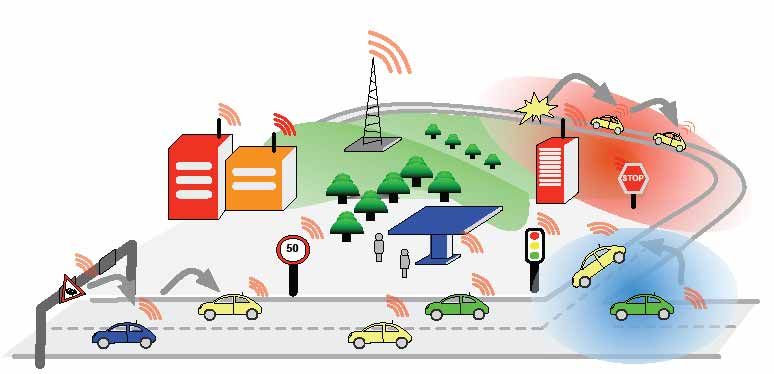
Figure 1 The system requirements are derived from various use cases
As shown in Figure 1 several actors are involved in C2X Communication. Those actors are:
• the drivers, which benefit from the system by receiving warning messages and route
recommendations,
• road operators, who receive traffic data and are therefore enabled to control the traffic in a
more efficient way,
• hotspot and Internet service providers, who can attach vehicle communication systems e.g. at
gas stations.
In the following, several safety and non-safety use cases are exemplarily described.
2.1 Safety
Version Date Number of page
1.1 August 28, 2007 12/94. C2C-CC Manifesto Page 13
C2C-CC
Safety use cases are those where a safety benefit exists when the vehicle enters into a scenario
applicable to the use case. In this section, we exemplarily introduce three safety use cases and
describe their operation. In general, a variety of requirements can be derived from the description
provided.
2.1.1 Cooperative Forward Collision Warning
Typical causes of rear-end collisions are driver distraction or sudden braking ahead of a following
vehicle. In all regions of the world, rear-end collisions cause a significant percentage of all accidents.
The Cooperative Forward Collision Warning use case provides assistance to the driver primarily to
avoid rear-end collisions with other vehicles. During normal driving, the equipped vehicles
anonymously share relevant information such as position, speed and heading. In order to predict an
imminent rear-end collision, each vehicle monitors the actions of its own driver and the position and
behavior of all other nearby vehicles. When the vehicle detects a critical proximity, the vehicle warns
the driver via visual, auditory, and/or haptic displays. Thus, the driver will have enough time to
intervene and avoid a crash. In addition to wireless communications, object detection sensors might
be used to identify vehicles that are not equipped with wireless communication.
As described above, the Cooperative Forward Collision Warning use case requires:
• the ability for all vehicles to share information with each other over a distance of approximately
20 to 200 meters in order to predict a rear-end collision,
• accurate relative positioning of the vehicles,
• vehicles to trust the information they receive from other vehicles,
• reasonable market penetration in order to have a safety impact.
2.1.2 Pre-Crash Sensing/Warning
The Pre-Crash Sensing/Warning use case addresses the next step beyond the Cooperative Forward
Collision/Warning use case. Here, the assumption is that a crash is unavoidable and will take place.
Similar to the Cooperative Forward Collision Warning use case use case, this use case requires that
all vehicles periodically share information from neighboring vehicles to predict a collision. Once a
collision is no longer avoidable (i.e., no possible way to steer or brake to avoid the crash), the involved
vehicles engage in fast and reliable communication to exchange information such as more detailed
position data and vehicle size. This extra information provided to both vehicles enables an optimized
usage of actuators such as air bags, motorized seat belt pre-tensioners, and extendable bumpers.
As described above, the Cooperative Forward Collision/Warning use case requires:
Version Date Number of page
1.1 August 28, 2007 13/94. C2C-CC Manifesto Page 14
C2C-CC
• the ability for all vehicles to share information with each other over a distance of approximately
20 to 100 meters in order to predict an unavoidable crash,
• accurate relative positioning of the vehicles,
• vehicles to trust the information they receive from other vehicles,
• reasonable market penetration in order to have a safety impact,
• a fast and reliable connection between two vehicles in case an unavoidable crash is detected.
2.1.3 Hazardous Location V2V Notification
The Hazardous Location V2V Notification use case utilizes the network of vehicles to share
information that relates to dangerous locations on the roadway, as for instance slippery roadways or
potholes. Thereby, a major issue is the generation of information about the driving condition at a
specific location. For instance, a vehicle that experiences an actuation of its ESP (Electronic Stability
Program) system, the vehicle retains information about the location and shares its knowledge with
other vehicles in the surrounding area. Vehicles that receive the information either provide it to the
driver or use it to automatically optimize its chassis or safety systems. The relevant information can
be shared with any number of vehicles over an area, limited only by the current density of equipped
vehicles. In addition to the case where the information is created in a vehicle, information from
external service providers can be accessed via a roadside unit and propagated through the vehicular
ad hoc network in the same manner.
As described above, the Hazardous Location V2V Notification use case requires:
• vehicles to trust the information originated by other vehicles,
• vehicles to trust the information originated by roadside units,
• reasonable market penetration in order to have a safety impact,
• the ability for vehicles to share information about a specific geographic area through multiple-
hops,
• the ability to evaluate and track the validity of the information shared through multiple-hops.
2.2 Traffic Efficiency
Traffic Efficiency use cases are those meant to improve efficiency of the transportation network by
providing information either to the owners of the transportation network or to the drivers on the
Version Date Number of page
1.1 August 28, 2007 14/94. C2C-CC Manifesto Page 15
C2C-CC
network. Those use cases primarily leverage the communication network provided by CAR 2 CAR to
either create new traffic related information or share existing information in a way that was not feasible
without CAR 2 CAR. A more efficient transportation system can result in fewer delays experience by
drivers or less road construction and maintenance costs to the owners of the transportation network.
Thus, traffic participants benefit from shorter travel times and road operators benefit from reduced
expenses to maintain the roadways.
2.2.1 Enhanced Route Guidance and Navigation
The Enhanced Route Guidance and Navigation use cases uses information collected by an
infrastructure owner to deliver route guidance information to a driver. Constantly, the infrastructure
owner is collecting data and predicting traffic congestion on roadways throughout a large region.
When an equipped vehicle travels by a roadside unit which supports the use case, the roadside unit
sends the vehicle information regarding current and expected traffic conditions throughout the region,
or perhaps, just for the route entered into the vehicle’s navigation unit. The vehicle uses this
information to inform the driver about expected delays or better routes that might exist due to the
traffic conditions. Because this use case is likely to route a number of people around congested
areas, the overall transportation system becomes more efficient with the use of alternate routes that
are not congested.
As described above, the Enhanced Route Guidance and Navigation use case requires:
• an infrastructure provider to collect and maintain the information on traffic congestion,
• vehicles to trust the information provided by the roadside unit,
• the ability for a roadside unit to offer a service to passing vehicles.
2.2.2 Green Light Optimal Speed Advisory
The Green Light Optimal Speed Advisory use case provides information to the driver in an effort to
make their driving smoother and avoid stopping. As a vehicle approaches a signalized intersection,
the vehicle receives information regarding the location of the intersection and the signal timing (i.e.,
number of seconds to switch from green to red light). With this information, the vehicle calculates an
optimal vehicle speed using the distance from the vehicle to the intersection and the time when the
signal is green. The vehicle notifies the driver of the optimal speed. If the vehicle travels at or near
the optimal speed, the traffic signal is likely to be green and the driver will not have to slow or stop the
vehicle. The effect of this use case is less stopping on roadways resulting in increased traffic flow and
increased fuel economy for equipped vehicles.
Version Date Number of page
1.1 August 28, 2007 15/94. C2C-CC Manifesto Page 16
C2C-CC
As described above, the Green Light Optimal Speed Advisory use case requires:
• a signalized intersection to transmit intersection position and traffic signal phase and
timing information for each direction of travel and each lane with individualized signal
timing,
• vehicles to trust the information provided by the traffic signal.
2.2.3 V2V Merging Assistance
The V2V Merging Assistance use case allows merging vehicles to join flowing traffic without disrupting
the flow of the traffic. When a vehicle enters an on-ramp to a limited access roadway, the vehicle
communicates with the traffic that will be adjacent to the vehicle when it attempts to merge into the
roadway. The vehicle requests specific maneuvers from the traffic participants in order to allow a safe
and non-disruptive merge into the regular traffic. With no objections from the traffic, the traffic will
either automatically adjust or will advise drivers in traffic on how to act. With the actions by the
merging traffic, the vehicle can enter the traffic flow without major disruptions to the flow. This use
case can also be extended to provide a ramp metering service where the merging vehicle is informed
when it may proceed on the on-ramp in order to merge into an empty space in traffic.
As described above, the V2V Merging Assistance use case requires:
• the ability for all vehicles to share information with each other over a distance adequate
to perform the merging maneuver,
• vehicles to trust the information they receive from other vehicles,
• vehicles to agree on actions in order to allow space for a merging vehicle.
2.3 Infotainment and Others
The category of use cases named Infotainment and Others is meant to capture the remaining use
cases which are not directed at Safety or Traffic Efficiency. Many of these use cases interact more
directly with the vehicle owner on daily basis providing entertainment or information on a regular basis.
Others are transparent to the driver but still perform a valuable function such as increasing fuel
economy or allowing diagnostic information to be accessed more efficiently at a service garage.
2.3.1 Internet Access in Vehicle
The Internet Access in Vehicle use case allows for a connection to the Internet. This enables the use
of all kinds of common IP based services in the vehicle. Therefore, a multi-hop route to an RSU is
established and maintained that acts as an Internet gateway. The multi-hop route is transparently
Version Date Number of page
1.1 August 28, 2007 16/94. C2C-CC Manifesto Page 17
C2C-CC
masked to above layers of the protocol stack and therefore enables almost any IP based protocol and
service to be deployed in the vehicles. This use case enables the benefits obtainable with the freedom
for the vehicle or driver to access any type of information available on the Internet.
As described above, the Internet Access in Vehicle use case requires:
• the ability for a vehicle to connect to a roadside unit who offers the Internet connection,
• the ability for a vehicle to address Internet servers through the roadside unit,
• the ability to multi-hop messages to a roadside unit from a vehicle when the two cannot
communicate directly with one another,
• a dynamic route maintenance that ensures the necessary service quality parameters and
resets the multi-hop route when necessary,
• as an alternative scenario, also supported by C2C Communication Systems: To connect
to a regular hotspot running IEEE 802.11 a, b, g WLANs.
2.3.2 Point of Interest Notification
The Point of Interest Notification use case allows local businesses, tourist attractions, or other points
of interest to advertise their availability to nearby vehicles. In this case, a roadside unit broadcasts
information regarding a point of interest such as its location, hours of operation, and pricing. The huge
amount of information is filter by the vehicles in a situation adaptive manner and when appropriate
presented to the driver. For instance, if the fuel gauge is low, the vehicle could show the driver
locations and prices for fueling stations in the immediate area. The benefit of this use case is that
advertising becomes more effective in that the audience is within the geographic area and may be
more likely to visit than someone listening to an FM broadcast or surfing the Internet hundreds of
kilometers away. The benefit to consumers is up-to-date information from a business in the proximity.
As described above, the Point of Interest Notification use case requires:
• vehicles to trust the information originated by roadside units,
• the ability for a roadside unit to broadcast information to surrounding vehicles.
2.3.3 Remote Diagnostics
The Remote Diagnostics use case allows a service station to assess the state of a vehicle without
making a physical connection to the vehicle. When a vehicle enters the area of a service garage, the
service garage can query the vehicle for its diagnostic information to support the diagnosis of the
problem reported by the customer. Even as the vehicle approaches, the vehicles’ past history and the
customers’ information can be retrieved from a database and be ready for the technician to use. If
software updates are required, the system can install the updates also without the physical
Version Date Number of page
1.1 August 28, 2007 17/94. C2C-CC Manifesto Page 18
C2C-CC
connection. This use case can reduce the amount of time necessary to serve a customer during a
visit to a service garage. This will also result in lower costs for repair and less waiting times for
customers.
As described above, the Remote Diagnostics use case requires
• vehicles to establish a trusted and secure connection with a roadside unit at a service
garage,
• the ability for a vehicle to identify itself when requested by an authorized requestor.
Version Date Number of page
1.1 August 28, 2007 18/94. C2C-CC Manifesto Page 19
C2C-CC
3 System Prerequisites and Constraints
The C2X Communication System is principally a distributed and self-organizing mobile communication
network which is able to cope with intermittent access to the communication infrastructure. As it is
well-known for conventional communication systems, standardization of the communication protocols
ensures interoperability at the network level. A specific aspect of C2X Communication is the
requirement to standardize also active safety applications. A C2X Standard for application need to
comprise methods for hazard detection and classification, data structures exchanged among cars, and
their interpretation by receiving cars.
The prerequisites and constraints for a successful operating system can be separated in two main
groups:
• economical prerequisites and constraints, and
• technical prerequisites and constraints.
In this chapter, we explain and discuss the economical issues followed by the technical issues in
detail.
3.1 Economical Prerequisites and Constraints
C2X Communication allows for autonomous exchange of data among vehicles. The CAR 2 CAR
Communication Consortium provides a technical platform for a wide range of applications. Among
these, safety and traffic flow applications are most appealing, as they hold the potential for improving
the traffic situation to an extent that would be difficult to realize with alternative technologies to
vehicular communication. Obviously, C2C-CC technology requires a certain distribution in the market
before it can show any effect. The required penetration [1] is estimated to
• at least 10 % of all cars for inter-vehicle danger warning applications,
• and about 5 % for traffic information propagation.
One of the economical challenges is the fact that cooperative systems do not constitute an immediate
value to the customers. A reluctant introduction may refrain potential new customers from equipping
their car with a C2X Communication System, which eventually results in a chicken-and-egg problem.
New strategies for the introduction of these systems need to be developed. This issue has been
identified and market introduction and business cases will be studied in detail.
Version Date Number of page
1.1 August 28, 2007 19/94. C2C-CC Manifesto Page 20
C2C-CC
A system, which supports only with a certain minimum penetration rate, cannot be deployed.
Therefore the C2C-CC communication system supports applications which communicate between
vehicles and road-side units. It would also be highly beneficial to support applications which are based
on the Internet protocol family in addition to active safety applications. These applications may include
general access to the Internet and provide all kind of information delivery to cars’ passengers and
various comfort functions.
Even in an optimal introduction scenario, where every new car will be equipped with a C2C-CC
Communications System from a certain date onwards, older cars without a communication system will
remain on roads. In such a case, it will take
• about one and a half years to reach 10% penetration in the field,
• and more than 6 years to reach 50%.
Clearly, the introduction phase until a minimum penetration rate is reached would be even prolongated
the lower the equipment rate. As a consequence, the C2X Communication System must be able to
work in scenarios with low penetration and high penetration rates.
In order to overcome the hurdle of low penetration rates in the initial phase, the C2X Communication
System can provide communication capabilities for Internet protocols and provide Internet services
and applications. Another strategy attempts to create a benefit for the vehicle manufactures during
production and service with all cars having a wireless interface. The combination of both strategies
may re-finance the C2C-CC Communication System.
Yet aanother option for solving the problem of the market introduction of (stand-alone) C2C-CC
Communication Systems is based fixed stations and road side units by third parties, e. g. by the
government. The infrastructure would allow for a set of applications from the very first car equipped
with a C2X Communication System. Examples for such applications are traffic signal violation warning,
in-vehicle signing or electronic payment.
In fact, the technical principles and system architecture of the C2X Communication System
incorporate communication of cars with fixed stations and road side units. All protocols and parts of
the communication system shall therefore take into account the additional stationary nodes,
applications and network load.
In summary, only a joint initiative of all European vehicle manufactures, suppliers, scientific
organizations and standardization bodies will lead to an economically promising and successful
market introduction.
Version Date Number of page
1.1 August 28, 2007 20/94. C2C-CC Manifesto Page 21
C2C-CC
3.2 Technical Prerequisites and Constraints
3.2.1 Anonymity and Data Security
The C2C-CC Communication System enables cars to exchange data. Although some of the
applications could rely on simple message propagation in some of the scenarios, other applications
and situations are also necessary in which data has to be relayed to one or more specific nodes,
identifiable through an identifier. On the other hand, anonymity of the vehicle and its driver must be
protected to a level at least comparable to which users of mobile phones feel comfortable with, today.
One of the technical approaches to accomplish anonymity is based on the use of temporary identifiers
instead of fixed ones.
Furthermore, the importance of privacy is different in European countries due to historic experiences
and the legal regulations. In some countries privacy is mandatory due to customer request or by law.
In other countries laws enforce the technical capability of driver identification in every situation.
Consequently, the C2X System must incorporate the different requirements for anonymity and security
across Europe.
For the success of C2C-CC Communication Systems a reliable system with a high availability is of
great importance. In case a driver would receive incorrect data several times, the driver would not trust
its technical features. Such incorrect data can be caused by malfunctioning or malicious users and can
have a severe effect on the C2X System. As a technical pre-requisite, it should not be possible for
anyone to send a false data, such as a warning message using a notebook from a position close to
the street. A technical approach to accomplish this feature is based on digital signatures and
certificates.
Finally, legal questions such as liability issues are currently regarded to be out of scope of the C2C-
CC. However, they also represent an important prerequisite, for example in a scenario where a
useless or wrong message provokes a change of driving behavior and eventually results in a road
accident. It is unclear who might be held responsible in this case. The situation will become even more
complicated when co-operative driving applications based on C2C-CC appear in the market.
3.2.2 Effective Protected Frequency Band
For safety applications, the C2X Communication needs to be robust in all situations and ensure a
certain quality of service level, e.g. a minimum latency and a maximum reliability when sending,
forwarding or receiving messages. This cannot be guaranteed when other non-safety communication
uses the same frequency band and consumes a considerable share of the available bandwidth. A
Version Date Number of page
1.1 August 28, 2007 21/94. C2C-CC Manifesto Page 22
C2C-CC
safety critical message must reach all receivers in time, even if a user in another car simultaneously
downloads a video from the Internet using a standard WLAN access point.
If the system would use open bands like the ISM, robust communication and the required quality of
service cannot be guaranteed. For this reasons, the C2C-CC supports the allocation of an effectively
protected frequency band.
The following Fehler! Verweisquelle konnte nicht gefunden werden. shows the requested
frequency band and channel usage for Europe.
European Common Allocation
ISM
Part 2 Part 1 Part 2
road critical road road safety and
safety and safety traffic efficiency
traffic
non-safety- efficiency
related focus on IVC focus on R2V
IVC and R2V focus
on R2V
channel
control
DFS required
5,855 5,875 5,885 5,905 5,925 GHz
Figure 2 Requested frequencies in Europe (taken from ETSI TR 102 492-2)
The band designated for safety critical applications with focus on (but not limited to) CAR 2 CAR
Communication, is located in the band between 5.885 and 5.905 GHz. The allocation process is still
ongoing.
The current status of frequency allocation is described in the following documents:
• ETSI TR 102 492-1 V1.1.1 (2005-06) - Technical Report; Electromagnetic compatibility
and Radio spectrum Matters (ERM); Intelligent Transport Systems (ITS); Part 1:
Technical characteristics for pan-European harmonized communications equipment
operating in the 5 GHz frequency range and intended for critical road-safety applications;
System Reference Document,
• ETSI TR 102 492-2 V1.1.1 (2006-03) -Technical Report; Electromagnetic compatibility
and Radio spectrum Matters (ERM); Intelligent Transport Systems (ITS); Part 2:
Technical characteristics for pan European harmonized communications equipment
operating in the 5 GHz frequency range intended for road safety and traffic management,
and for non-safety related ITS applications; Draft System Reference Document.
3.2.3 Scalability
Version Date Number of page
1.1 August 28, 2007 22/94. C2C-CC Manifesto Page 23
C2C-CC
The C2C Communication System must work in situations with a very small density of road traffic and
in situations with a very high traffic density, such as traffic jams or major intersections. These two
situations cause different technical challenges. In sparse situations, a car is often out of the
transmission range of other cars that potentially could forward data. In dense situations, the data traffic
of all cars can exceed the available bandwidth and overload the network. The CAR 2 CAR system has
to support and seamlessly scale between both extreme situations.
Also, it can be foreseen that in the market introduction phase very few cars are equipped with C2C
Communication Technology (see Section 3.1). In fact, this problem is similar to the two scenarios with
opposite traffic densities. Even the first systems introduced in the market must be able to handle
situations with high traffic density, because this car might be still in operation even several years after
their production.
It is necessary in all cases, that a first generation system is compatible with systems of later
generations.
3.2.4 Mandatory Sensor Data
The integration of a C2C Communication System into a car is not addressed by the C2C-CC and is in
the responsibility of individual car manufacturer and its automotive supplier. However, a certain set of
preconditions must be fulfilled for integration. This mainly comprises the availability of a basic set of
sensor data, however quality and security issues also play an important role.
For sensor data which are mandatory for the system, data structures and certain characteristics have
to be specified. One prominent example is position data, which are needed by the communication
system and by many applications. While for the communication system itself accuracy comparable of
those delivered of today’s GPS system is sufficient, some applications may need much higher
precision. If applications need more accurate position data or positions at more frequent updates, it is
the task of the application designer to get this data delivered by in-car systems or off-board servers. It
must also be noted that GPS is not compulsory for the C2C-CC System. Any other positioning system
that fulfills the requirements may be used instead.
The C2C-CC will specify a data structure (including properties like accuracy, freshness, update rate
etc.) which must be supported by each system in each vehicle. The following non-exhaustive list of
parameters is regarded as mandatory sensor data, which have to be provided by the in-car system
are:
• Position data,
• Vehicle speed,
• Driving direction,
Version Date Number of page
1.1 August 28, 2007 23/94. C2C-CC Manifesto Page 24
C2C-CC
• Hazard warning signal flasher,
• Brake power / vehicle deceleration,
• ABS, ESP and ASR sensors,
• Rain sensor / wiper status.
The first three parameters are required by the C2C-CC Communication System itself and can be
utilized by the applications. All other listed parameters are needed for the applications and it is not
finally decided if they are mandatory or not. With additional applications possible, there will be more
sensor data necessary.
Currently, the method to collect sensor data is regarded to be out-of-scope of the C2C-CC. Sensors
might be directly connected to the C2C-CC communication system and the system would read data
from a vehicle’s internal network. Alternatively, a direct link between the C2X system to an electronic
control unit of the car via a suitable interface may exist. The C2C-CC generalizes from this scheme
and considers only the properties of the parameters.
Version Date Number of page
1.1 August 28, 2007 24/94. C2C-CC Manifesto Page 25
C2C-CC
4 System Architecture
This chapter describes the C2C Communication System architecture at a high abstraction level. It
explains core components and their interaction, the protocol architecture, and main interfaces.
4.1 System Overview
The draft reference architecture of the C2C Communication System is shown in Figure 3. It comprises
three distinct domains: in-vehicle, ad hoc, and infra-structure domain.
The in-vehicle domain refers to a network logically composed of an on-board unit (OBU) and
(potentially multiple) application units (AUs). An AU is typically a dedicated device that executes a
single or a set of applications and utilizes the OBU’s communication capabilities. An AU can be an
integrated part of a vehicle and be permanently connected to an OBU. It can also be a portable device
such as laptop, PDA or game pad that can dynamically attach to (and detach from) an OBU. AU and
OBU are usually connected with wired connection, but the connection can also be wireless, such as
using Bluetooth, WUSB or UWB. The distinction between AU and OBU is logical; they can also reside
in a single physical unit.
The ad hoc domain, or Vehicular Ad hoc Network (VANET), is composed of vehicles equipped with
OBUs and stationary units along the road, termed road-side units (RSUs). An OBU is at least
equipped with a (short range) wireless communication device dedicated for road safety, and
potentially with other optional communication devices. OBUs form a mobile ad hoc network (MANET)
which allows communications among nodes in a fully distributed manner without the need for a
centralized coordination instance. OBUs directly communicate if wireless connectivity exists among
them. In case of no direct connectivity, dedicated routing protocols allow multi-hop communications,
where data are forwarded from one OBU to another, until it reaches the destination. The primary role
of an RSU is the improvement of road safety, by executing special applications and by sending,
receiving or forwarding data in the ad hoc domain in order to extend the coverage of the ad hoc
network. OBUs and RSUs can be seen as nodes of an ad hoc network, respectively mobile and static
nodes. An RSU can be attached to an infrastructure network, which in turn can be connected to the
Internet. As a result, RSUs may allow OBUs to access the infrastructure. In this way it is possible for
AUs registered with an OBU to communicate with any host on the Internet, when at least one
infrastructure-connected RSU is available.
Version Date Number of page
1.1 August 28, 2007 25/94You can also read