USER'S GUIDE - PL-01-0040 - Hologic
←
→
Page content transcription
If your browser does not render page correctly, please read the page content below
Acessa® ProVu System User’s Guide                  PL-01-0040

                                    USER’S GUIDE

CO 20-11 Revision: B                                       1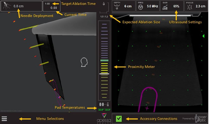
Acessa® ProVu System User’s Guide                                                           PL-01-0040

                                                         10.14.    Shutting Down the System                 19
1.         Introduction                              3   11.       Special Considerations: General Ablation
2.         Indications For Use                       3             Procedures                               20
3.         Device Description and Components         3   11.1.     Highly Vascularized Tissue               20
4.         Contraindications                         5   11.2.     One or More Electrode Arrays in a Duct or
5.         Warnings                                  5             Vessel                                   20
5.1.       General Warnings                          5   11.3.     Ablation of Dense or Calcified Fibroid
5.2.       Environmental and EMI Warnings            6             Tissue                                   20
5.3.       Warnings During Electrosurgical Device        12.       Ex-Vivo Studies                          20
           Use                                       7   12.1.     Ex-Vivo Studies                          20
5.4.       Warnings Specific to the Acessa ProVu         12.2.     Representative Ablation Shape per
           System                                    7             Deployment                               20
5.5.       Warnings Concerning Acessa ProVu System       12.3.     Results from Ex-Vivo Bovine Liver Studies
           Guidance Accuracy                         7                                                      21
5.6.       Warnings Specific to Uterine Fibroid          12.4.     Representative Ablation Sizes in Ex-vivo
           Ablation                                  7             Bovine Liver with Settings in Temperature
6.         Precautions                               8             Control                                  21
6.1.       General Precautions                       8   13.       Clinical Studies – Fibroids              21
6.2.       Environmental and EMI Precautions         8   13.1.     Study Design                             22
6.3.       Precautions During Electrosurgical Device     13.2.     Study Objectives                         22
           Use                                       8   13.2.1.   Primary Objectives                       22
6.4.       Precautions Specific to the Acessa ProVu      13.2.2.   Secondary Objectives                     22
           System                                    8   13.2.3.   Inclusion and Exclusion Criteria         22
6.5.       Precautions Concerning Acessa ProVu           13.3.     Study Demographics                       22
           System Guidance Accuracy                  8   13.4.     Fibroid Symptoms and Characteristics
6.6.       Precautions Specific to Uterine Fibroid                 Reported at Baseline – All Subjects      23
           Ablation                                  8   13.5.     Treatment                                23
7.         Sterilization and Safety Checks           9   13.6.     Results of the Pivotal Study             24
8.         Switches, Buttons, Connections, and           13.7.     Safety                                   24
           Display                                   9   13.8.     Efficacy                                 25
8.1.       Front Panel                               9   13.9.     Surgical Reintervention Rate             25
8.2.       Buttons, Connections and Display          9   13.10.    Uterine and Fibroid Volume               25
8.3.       Rear Panel                               10   13.11.    UFS-QOL Scores                           26
8.4.       Switches and Connections                 10   13.12.    EQ-5D Health State Score                 27
9.         Setting up the Acessa ProVu System       11   13.13.    Overall Treatment Effect (OTE) Survey 27
9.1.       Connecting System Components             11   13.14.    Data regarding return to work and return
9.2.       Before Patient Arrives                   11             to normal activities                     27
9.3.       Patient Preparation                      11   13.15.    Data regarding pregnancy                 27
9.4.       Energizing The System                    12   13.16.    Data regarding calcified fibroids        27
10.        Use of the Acessa System                 12   13.17.    Therapeutic medications at 24 and 36
10.1.      Getting Ready                            12             months post-treatment                    27
10.2.      Accessory Connections                    13   14.       Postmarket Surveillance Study – TRUST
10.3.      User Interface                           14             (Treatment Results of Uterine Sparing
10.4.      Menu Setttings                           15             Technologies)                            28
10.5.      Ultrasound Settings                      15   14.1.     Summary of the Post-Approval Study
10.6.      Expected Ablation Size                   15             Methods                                  28
10.7.      Deployment, Ablation and Coag            15   14.1.1.   Study Objective                          28
10.8.      Pad Temperatures                         16   14.1.2.   Study Design                             28
10.9.      The Acessa ProVu Guidance System              14.1.3.   Study Population                         28
           Feature                                  16   14.1.4.   Data Source                              28
10.10.     Procedure Planning                       18   14.2.     Key Study Endpoints                      28
10.11.     Performing an Ablation                   18   14.2.1.   Primary Endpoint                         28
10.12.     Operation of System During Coag          19   14.2.2.   Secondary Endpoint                       28
10.13.     After the Procedure                      19   14.3.     Total Number of Enrolled Study Sites     28

     CO 20-11 Revision: B                                                                                  2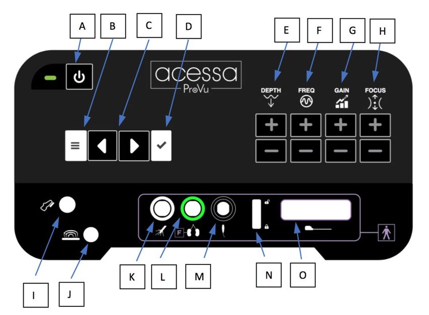
Acessa® ProVu System User’s Guide                                                        PL-01-0040

14.4.   Total Number of Enrolled Subjects and         18.1.   System Specifications                  31
        Follow-up Rate                           28   18.2.   Guidance and Manufacturer’s Declaration
14.5.   Study visits and length of follow up     28           –                                      32
14.6.   Summary of the Post-Approval Study            18.3.   Technical Characteristics              35
        Results                                  29   18.4.   Compliance to Safety and Performance
14.6.1. Final safety findings (key endpoints)    29           Standards                              36
14.6.2. Study Strengths and Weaknesses           30   19.     Trouble Shooting                       36
15.     Potential Risks of Acessa ProVu System   30   19.1.   Faults, Alerts, and Errors             36
16.     Patient Counseling                       31   19.2.   Fault/Alert Code Table                 36
17.     Care and Maintenance                     31   20.     Glossary of Symbols and Product Graphics
17.1.   Software Upgrades and Installation       31                                                  39
17.2.   Maintenance                              31   20.1.   Symbols                                39
17.3.   Cleaning and Disinfecting the Console    31   20.2.   Product Graphics Glossary              40
17.4.   Calibration Verification                 31   21.     Warranty Statement                     41
18.     Specifications                           31

  CO 20-11 Revision: B                                                                              3
Acessa® ProVu System User’s Guide PL-01-0040
1. Introduction
Acessa Health Inc. is dedicated to providing service and support to its customers. If there are any questions concerning the use
of the Acessa ProVu System, please contact Customer Service at:
MANUFACTURED FOR:
Acessa Health Incorporated
317 Grace Lane, Suite 200
Austin, TX 78746 USA
Telephone: 877.412.3828
Fax: 925.605.0327
Email: customerservice@acessahealth.com
2. Indications For Use
The Acessa ProVu System is indicated for use in percutaneous, laparoscopic coagulation and ablation of soft tissue, including
treatment of symptomatic uterine fibroids under laparoscopic ultrasound guidance.
The Acessa ProVu System includes optional electromagnetic guidance for enhancing the ultrasonic image of the Acessa ProVu
Handpiece and for predicting its future path on a computer monitor screen which also shows the ultrasound B-scan image.
3. Device Description and Components
The Acessa ProVu System provides radiofrequency (RF) ablation, ultrasound and guidance within a single console and includes
additional accessories.
The Acessa ProVu System is designed to deliver monopolar radiofrequency (RF) energy to tissue through a disposable Handpiece.
The System is capable of delivering up to 200W of power. The Console is specifically designed to be used only with Acessa Health
manufactured devices. The Acessa ProVu System has temperature or power displayed depending on the mode being used to
assist the physician in monitoring and controlling the ablation throughout the procedure.
The Acessa ProVu System must be used under laparoscopic ultrasound guidance. The basic function of ultrasound is to acquire
ultrasound echo data and to display the image in ultrasound B-Mode. Ultrasound wave pulses released from transducer are
reflected at the internal body system. Reflected waves are transmitted from the transducer, and ultrasound images are produced
with the reflected image on the monitor. The system is designed for imaging with the Acessa ProVu System Transducer (5-12
MHz).
The Acessa Guidance System feature is an advanced electromagnetic spatial tracking system designed to calculate the position
and orientation of sensors within a defined volume. The sensors are embedded in the tip of the Acessa ProVu Handpiece and the
Acessa ProVu Transducer with Sensor, so that the system can determine the position and orientation to each other within the
patient’s abdominal cavity and display an animated image on a monitor.
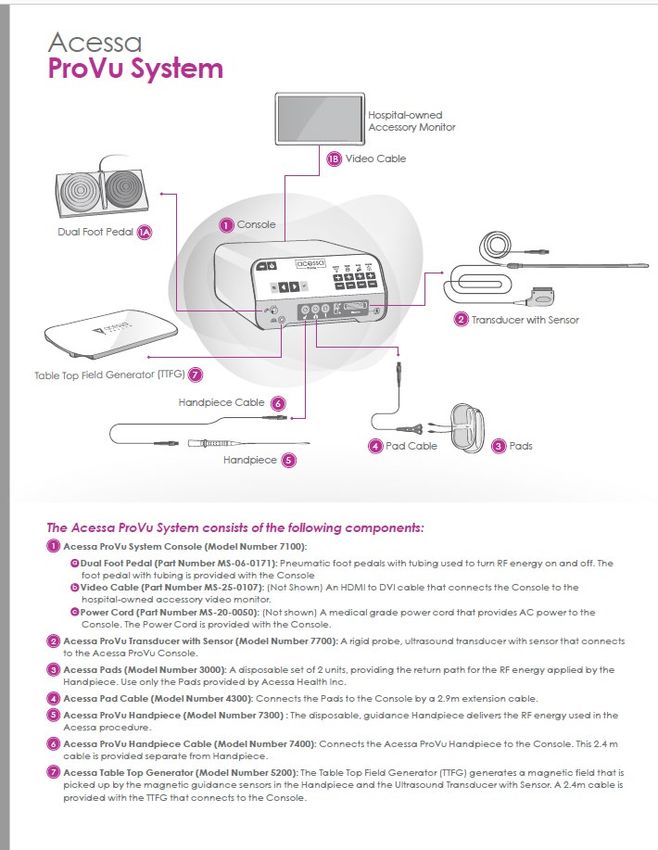
The Acessa ProVu System consists of:
The Console contains the following hardware and electronic components:
• RF Ablation system
• Ultrasound system
• Guidance system
The following accessories connect to the Console:
• Dual Foot Pedal (one for RF, one for coagulation)
• Video Cable
• Power Cord
• Acessa Pad (For IFU see PL-01-0015) and Acessa Pad Cable (For IFU see PL-01-0012)
• Acessa ProVu Handpiece (For IFU see PL-01-0038) and Acessa ProVu Handpiece Cable (For IFU see PL-01-0041)
• Acessa ProVu Transducer with Sensor (For IFU see PL-01-0044)
• Acessa Table Top Field Generator and Table Pads (Not Shown)
• Monitor (Hospital-owned, not provided by Acessa Health Inc. Monitor must have at least a 1920 x 1080 resolution and 27”
or larger diagonal screen diameter preferred.)
CO 20-11 Revision: B 3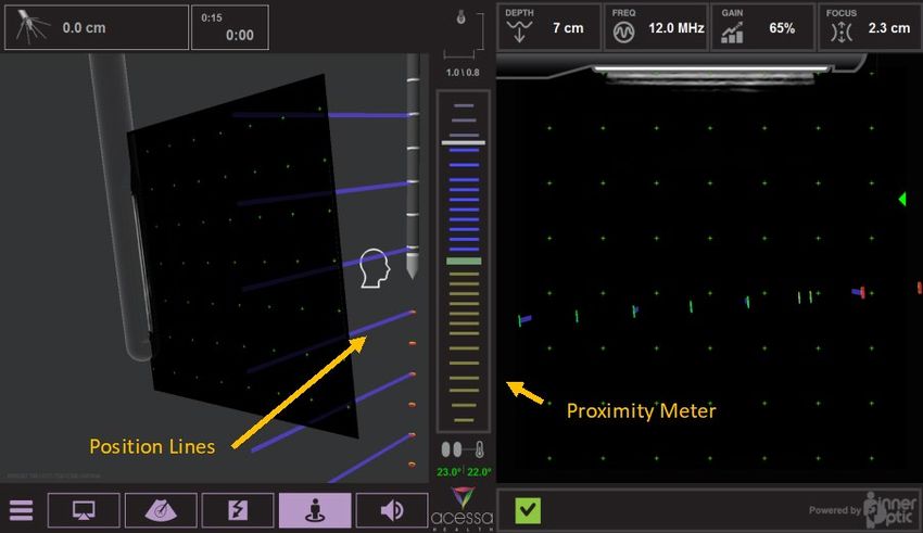
Acessa® ProVu System User’s Guide   PL-01-0040

CO 20-11 Revision: B                        4
Acessa® ProVu System User’s Guide                                                                                  PL-01-0040

4.   Contraindications
     •  Patients who are not candidates for laparoscopic surgery (e.g. patients with known or suspected intra-abdominal
        adhesions that would interfere with safe use of the Handpiece).
     •  Uterus adherent to pelvic tissue or viscera.
     •  Non-uterine pelvic mass.
     •  Acessa ProVu System’s guidance system is not intended for diagnostic use.
     •  The Acessa ProVu System’s guidance system may not be used to guide the tip of the Handpiece once the tip has
        penetrated the uterine serosa. Ultrasound visualization must be used during fibroid penetration and treatment.

5.   Warnings
     5.1. General Warnings
     •    The safety of the electrosurgery will be greatly enhanced by a thorough knowledge of the medical literature on the
          subject. Study of specific information on the hazards and complications of the procedure in question is especially
          recommended.
     •    Read all instructions for use of the Acessa ProVu System prior to its use. Safe and effective electrosurgery is dependent
          not only on equipment design but also on factors under control of the operator. It is important that the instructions
          supplied with this equipment be read, understood, and followed in order to enhance safety and effectiveness.
     •    The safety and effectiveness of the Acessa ProVu System’s electromagnetic tracking system to guide the tip of the
          Handpiece has not been evaluated in clinical trials. Therefore, the electromagnetic tracking system should only be used
          until the device has penetrated the uterine serosa.
     •    The Acessa ProVu System should only be used by physicians and qualified medical personnel trained in the safe use of
          electrosurgery and in the proper use of the Acessa ProVu System. After utilizing the Acessa ProVu System to determine
          the desired entry location into the uterus, the physician must verify the final placement of the Handpiece shaft and
          needles within the target tissue using ultrasound.
     •    DO NOT USE with hybrid trocar systems, i.e. a combination of metal and plastic, when using monopolar active
          components. This may result in alternate site burns due to capacitive coupling. Use only all-metal or all-plastic trocar
          systems.
     •    When not using instruments, place them in a clean, dry, highly visible area not in contact with the patient. Inadvertent
          contact with the patient may result in burns.
     •    Due to concerns about the carcinogenic and infectious potential of electrosurgical byproducts (such as tissue smoke
          plume and aerosols), protective eyewear, filtration masks, and effective smoke evacuation equipment should be used
          in laparoscopic procedures.
     •    DO NOT activate the Handpiece when not in contact with target tissue, as this may cause injuries due to capacitive
          coupling with other surgical equipment.
     •    The surface of the active electrode may remain hot enough to cause burns after the RF current is deactivated.
     •    Re-use of the Handpiece or Transducer Sleeve may result in patient post-operative infection. These accessories are for
          single use only.
     •    When positioning the Handpiece, confirm proper placement prior to initiating treatment (RF energy activation).
          Neuromuscular stimulation could cause injury due to unwanted muscle contractions.
     •    Electric shock hazard. Acessa ProVu System Console must only be used with an IEC/EN/UL/CSA 60950 or 60601-1
          certified monitor.
     •    Electric shock hazard. Do not remove the cover of the Console. Refer all service to Acessa Health Inc. There are no
          user-serviceable parts inside the Console.
     •    Electric shock hazard. Do not saturate the Console with liquids. Do not allow liquids to run inside the unit. Do not
          immerse the unit in water. Shut off the Console and disconnect power before cleaning. Do not sterilize the unit.
     •    Electric shock hazard. Console must only be connected to a supply mains with protective earth.
     • When applying the Pads as described in this document or the Pad IFU (PL-01-0015), if it is found that the Pads will
          overlap, the Acessa ProVu System cannot be used for that patient. SEVERE SKIN BURNS MAY RESULT.
     •    FOR SINGLE USE ONLY! Re-use of the Pads may result in patient burn and/or infection.
     •    FOR SINGLE USE ONLY! Re-use of the Handpiece may result in patient post-operative infection.
     •    Treatment of children is limited due to the physical size and placement of Pads with respect to RF ablation site.
     •    Treatment with the Acessa ProVu System is not recommended for nursing mothers or pregnant women.
     •    Electrosurgery is not recommended for patients with metal implants near the ablation site or along the RF return path
          to Pads.
     •    Safety of using heat or cryo during or following the Acessa procedure has not been studied.
     •    If the patient has a pacemaker, consult the patient’s cardiologist prior to this procedure. Using the Acessa ProVu System
          in the presence of an internal or external pacemaker may require special considerations.

 CO 20-11 Revision: B                                                                                                           5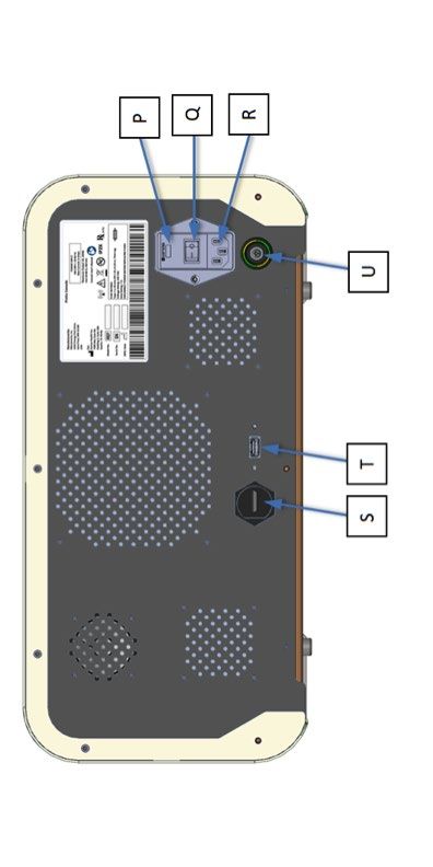
Acessa® ProVu System User’s Guide                                                                                  PL-01-0040

  •     In the case of a pacemaker, a possible hazard exists because interference with the action of the pacemaker may occur,
        and the pacemaker may become damaged. Questions should be directed to the attending Cardiologist, or to the
        pacemaker manufacturer.
  •     Do not use the Acessa ProVu System during cardiac defibrillation.
  •     The Transducer should not be used to manipulate the bowel during the procedure due to the risk of bowel injury.
  •     ONLY Acessa Health Inc. accessories may be attached to and used with the Acessa ProVu System. The Acessa ProVu
        System is not compatible with any other RF devices or electro-magnetic guidance devices.
   •    Use of accessories, transducers and cables other than those specified or provided by the manufacturer of this
        equipment could result in increased electromagnetic emissions or decreased electromagnetic immunity of this
        equipment and result in improper operation.
   •    For surgical procedures where the RF current could flow through parts of the body having a relatively small cross
        sectional area, the use of bipolar techniques may be desirable in order to avoid unwanted tissue damage.
   •    The device should not be used on patients with bleeding disorder or an anticoagulant therapy.
   •    No modification of this equipment is allowed.
   •    The connector of the TTFG must be positioned on the side of the patient opposite the physician.
   •    The Acessa ProVu System is sensitive to strong radiated and conducted electromagnetic interference. In the event of
        such interference, the Console will cease displaying guidance information and will display an alert message. The user
        should discontinue use of the Acessa ProVu System until the source of the interference can be determined and
        removed.

   5.2. Environmental and EMI Warnings
   •    In the case of a pacemaker, a possible hazard exists because interference with the action of the pacemaker may occur,
        and the pacemaker may become damaged. Questions should be directed to the attending Cardiologist, or to the
        pacemaker manufacturer.
   •    Any additional monitoring electrodes should be placed as far as possible from the Handpiece and should incorporate
        high-frequency current limiting devices. Needle monitoring electrodes are not recommended.
   •    Do not use flammable anesthetics, gases, or liquids while the system is in use. The risk of igniting flammable gases or
        other materials is inherent in electrosurgery and cannot be eliminated by device design. Precautions must be taken to
        avoid contact of flammable materials and substances with electrosurgical electrodes, whether they are in the form of
        an anesthetic or skin preparation agent, or produced by natural processes within body cavities, or originate in surgical
        drapes, tracheal tubes or other materials.
   •    ASPIRATE fluid from the area before activating the instrument. Conductive fluids (e.g. blood or saline) in direct contact
        with or in close proximity to an active electrode may carry electrical current or heat away from target tissues, which
        may cause unintended burns to the patient.
   •    There is a risk of pooling of flammable solutions under the patient or in body depressions such as the umbilicus, and in
        body cavities such as the vagina. Any fluid pooled in these areas should be removed before RF surgical equipment is
        used.
   •    The presence of endogenous gases may create an ignition hazard. Ensure that the operating room is well ventilated.
   •    Some materials, for example cotton, wool and gauze, when saturated with oxygen may be ignited by sparks produced
        in normal use of the RF surgical equipment.
   •    This equipment has been tested and found to comply with the EMC limits for the Medical Device (CISPR 11 Class A and
        IEC 60601-1-2). These limits are designed to provide reasonable protection against harmful interference in a typical
        medical installation, however, in some cases of input power fluctuations or transients (electrical fast transient,
        conducted immunity, and voltage dips/interrupts), compliance is achieved by safe shutdown into standby mode. If the
        unit responds to an EMI event by shutting down, then it will be necessary to manually reboot the system by use of the
        Standby pushbutton on the front of the Console. The equipment generates, uses, and can radiate radio frequency
        energy, and if not installed and used in accordance with these instructions, may cause harmful interference to other
        devices in the vicinity. Per the IEC 60601-2-2 standard, compliance to radiated emissions is only tested in the Ready
        Mode; however, during ablation or coagulation known interference will be generated which degrades nearby AM radio
        receivers and other equipment sensitive to harmonics of the 460 kHz RF Generator operating frequency. There is no
        guarantee that interference will not occur in a particular installation. If this equipment does cause harmful interference
        with other devices, which can be determined by turning the equipment off and on, the user is encouraged to try to
        correct the interference by one or more of the following measures:
        o Reorient or relocate the receiving device.
        o Increase the separation between the equipment.
        o Connect the equipment into an outlet on a circuit different from that to which the other device(s) is/are connected.
        o Consult the manufacturer or field service technician for help.
   •    The use of Pads, Handpiece, Cables, and accessories other than specified, with the exception of those devices sold by
        Acessa Health Inc. for the system as replacement parts for components may result in increased emissions or decreased
        immunity of the Acessa ProVu System.

CO 20-11 Revision: B                                                                                                           6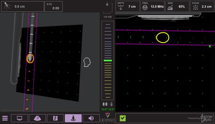
Acessa® ProVu System User’s Guide                                                                                 PL-01-0040

  •     Electric shock hazard. Do not saturate Console with liquids. Do not allow liquids to run inside the unit. Do not immerse
        the Console in water. Shut off the Console and disconnect power before cleaning. Do not sterilize the Console or Pads.

  5.3. Warnings During Electrosurgical Device Use
  •    Pad temperatures normally remain within a few °C of their starting temperature but occasionally can rise further for
       long ablations or higher than normal tissue impedance. The user is advised to have an external cooling system setup
       nearby in standby for this contingency. Do not use dry ice.
  •    Cables connected to the device should not contact the patient or other electrical leads.
  •    Skin-to-skin contact, such as between the torso and the arms or between the legs of the patient should be avoided by
       insulating these contacts with sheets or dry gauze.
  •    Keep the Handpiece active electrode arrays clean. Build-up of eschar may reduce the instrument’s effectiveness. Do
       not activate the instrument while cleaning. Injury to operating room personnel may result.
  •    Do not touch the Handpiece tip and Pads at the same time especially when operating the Console, as capacitive coupling
       may lead to burns.
  •    When using the device in situations where vision may be limited, burns may result if the device is activated outside the
       field of view.
  •    Failure of high frequency surgical equipment could result in an unintended increase of output power.
  •    Ablation RF Output is active without continuous activation of the Foot Pedal. Care needs to be taken to avoid over-
       exposure of RF energy which may result in tissue damage or adjacent tissue damage.
  •    When not in use, electrosurgical leads (active or return) should be positioned so that they cannot come into contact
       with the patient, other leads or any metal objects.

   5.4. Warnings Specific to the Acessa ProVu System
   •    Apparent low power output or failure of the electrosurgical equipment to function correctly at normal settings may
        indicate faulty application of the Pads or failure of an electrical lead.
   •    For monopolar surgery, effective contact between the patient and the Pads must be verified whenever the patient is
        repositioned.
   •    The proper use and placement of the Pads are key elements in the safe and effective use of monopolar electrosurgery,
        particularly in the prevention of burns. Follow directions and recommended practices for the preparation, placement,
        surveillance, removal and use of the Pads. Use with the system in accordance with your facility’s standard operating
        procedure, Acessa Health’s instructions, and AAMI standards.

   5.5. Warnings Concerning Acessa ProVu System Guidance Accuracy
   •    Do not use the Acessa ProVu System guidance system without the Table Top Field Generator (TTFG) and Pad Set (MS-
        26-0022). The generator should be below the patient’s pelvis.
   •    Do not drop the Field Generator or subject it to impact. Physical damage to the Field Generator may alter its calibration
        and contribute to inaccurate guidance.
   •    Do not place the Acessa ProVu System closer than 1m from the Field Generator. To do so may affect the tracking
        accuracy.
   •    Only plastic or compatible metals may be in the magnetic field. The Acessa ProVu System guidance system works by
        generating magnetic fields from its TTFG. Take care when using the system to not place ferromagnetic objects upon the
        Field Generator or within the tracking volume, or accuracy may be affected. Those metals specifically known to cause
        tracking disruptions are: mild steels such as DIN 1.4034 or DIN 1.4021, Aluminum alloys and 400 series stainless steel.
        The following metal alloys do not affect the Acessa ProVu System: titanium (TiA16V4); and 300 series stainless steel.
   •    Do not coil the TTFG cable or place it inside the tracking volume or wrap it around the TTFG, as it may create magnetic
        interference.
   •    Do not place the Handpiece cable within 30 mm of the TTFG cable.
   •    Do not wrap the Handpiece cable around the Transducer cable or Console cables.

   5.6. Warnings Specific to Uterine Fibroid Ablation
   •    Insufficient data exist on which to evaluate the safety and effectiveness of Acessa procedure in women who plan future
        pregnancy. Therefore, the Acessa procedure is not recommended for women who are planning future pregnancy.
   •    To reduce the risk of injury to organs outside of the uterus, electrode tips must be deployed no closer than 1 cm from
        the fibroid margin in all planes.
   •    Always verify that the electrode arrays are fully retracted before positioning, advancing, or withdrawing the Handpiece.
   •    The Handpiece tip should be allowed to cool for at least 60 seconds after the ablation has stopped, prior to removing
        it from the target tissue.
   •    To reduce the risk of hematoma, identify the inferior epigastric arteries prior to percutaneous insertion of the
        Handpiece.

CO 20-11 Revision: B                                                                                                          7
Acessa® ProVu System User’s Guide                                                                                     PL-01-0040

       •    The safety and effectiveness of the Acessa procedure has not been evaluated in women with uterine size >14 weeks.
       •    Uterine tissue may contain unsuspected cancer, particularly in patients who are peri- or post-menopausal. Insufficient
            data exist on which to evaluate the safety and effectiveness of Acessa procedure for treatment of cancerous uterine
            tissue. Thoroughly discuss the benefits and risks of all treatments with patients.
       •    Do not substitute transabdominal or transvaginal ultrasound for laparoscopic ultrasound when performing the Acessa
            procedure.

6.     Precautions
       6.1. General Precautions
       •    Do not use the Acessa ProVu System if any of the hardware components, cables, or connectors are damaged. Such
            damage may affect system functionality.
       •    If the system becomes unresponsive during a procedure, reboot the system. If the problem persists, call Acessa Health
            Inc. customer service, refer to §1 for applicable contact information.
       •    Reusable accessory cables should be periodically inspected for damage to insulation and tested for function and safety
            in accordance with the cable’s instructions for use.
       •    The Hospital-owned accessory video monitor (an IEC/EN/UL/CSA 60950 or 60601-1 certified monitor) must have at
            least a 1920 x 1080 resolution and a DVI input. A 27” or larger diagonal screen is preferred.
       •    Position the Console to allow adequate ventilation during operation.
       •    Arrange cables to minimize trip hazard and avoid damage.
       •    Position the Console to allow easy access to the On/Standby power switch on front of Console.
       •    Dispose of used Handpieces, Pads, and Cables in accordance with local, state, and national bio-waste laws and
            regulations.
       •    Always turn the Console power OFF before connecting or disconnecting the power cord and TTFG cable. Not doing so
            may result in sparks being generated.
       •    The Console should not be used adjacent to or stacked with other equipment. The system should be observed to verify
            normal operation in the configuration in which it will be used.
       •    Portable and mobile radio frequency (RF) communications equipment can affect the Acessa ProVu System functionality.
       •    Do not expose the Handpiece or Transducer with Sensorto a high magnetic field such as a Magnetic Resonance Imaging
            (MRI) scanner, as they may become magnetized and affect system functionality.
       •    Mains power quality should be that of a typical commercial or hospital environment. If the user of the Acessa ProVu
            System requires continued operation during power mains interruptions, it is recommended that the Console be
            powered from an uninterruptible power supply.
       •    Do not use abrasives, caustics, or mineral spirits. Use of these agents to clean the Console or any of its accessories may
            cause damage and voids the warranty. All electrical connection ports must be air-dried before use.
       •    The output power selected should be as low as possible for the intended purpose.

6.2.        Environmental and EMI Precautions
       •    Non-flammable agents should be used for cleaning and disinfection wherever possible. (See Cleaning and Disinfecting
            instructions and precautions for the validated cleaning agent. (§17.3)
       •    Interference produced by operation of high-frequency surgical equipment may adversely affect the operation of other
            electronic medical equipment such as monitors and imaging systems. This can be minimized or resolved by rearranging
            monitoring device cables so they do not overlap the Acessa ProVu System’s cables.

6.3.        Precautions During Electrosurgical Dev ice Use
       •    Due to the non-homogenous conduction that occurs near organ surfaces or vasculature, shapes of ablations performed
            in these areas may be altered. Careful planning is needed for targets in these locations
       •    Any application or procedure that alters tissue perfusion and affects temperature elevation should be monitored
            carefully.

6.4.        Precautions Specific to the Acessa ProVu System
       •    A USB flash memory device is the only device that should be inserted into the back panel USB port (USB port, Item T as
            shown in §8.4). This port is for Acessa Health personnel only.

6.5.        Precautions Concerning Acessa ProVu System Guidance Accuracy
       •    The System’s guidance capability has ±10 mm accuracy.

6.6.        Precautions Specific to Uterine Fibroid Ablation
       •    Avoid excessive pressure (e.g. lateral pressure) on the Handpiece which could bend or damage the shaft and/or
            electrode array.

 CO 20-11 Revision: B                                                                                                              8
Acessa® ProVu System User’s Guide                                                                              PL-01-0040

       •    To avoid damage to the electrode arrays, maintain stability of the uterus position and do not rotate the Handpiece
            when electrodes are deployed in tissue.

7.     Sterilization and Safety Checks
       •   Inspect the Handpiece and Pads packaging for damage.
       •   Inspect the Handpiece and and Pads for any obvious damage.
       •   Inspect the medical grade power cord for insulation damage or frayed wire connections.
       •   Sterilize the Transducer in accordance with the recommended process in the Instructions for Use accompanying the
           Acessa ProVu Transducer with sensor. Ensure that the cable interconnections are clean and dry prior to use.
       •   Clean and sterilize the Handpiece Cable in accordance with the recommended process in the Instructions for Use
           accompanying the Handpiece cable. Ensure that the cable interconnections are clean and dry prior to use.
       •   Clean and disinfect the Pad Cable in accordance with the recommended process in the Instructions for Use
           accompanying the cable. Ensure that the Pad cable interconnections are clean and dry prior to use.
       •   The Console, Foot Pedal, and Field Generators (TTFG) should be cleaned and disinfected per §17.3.

8. Switches, Buttons, Connections, and Display
8.1.   Front Panel

8.2.        Buttons, Connections and Display
       A.   On/Standby Button, LED Indicator
                    Push to turn Console ON (LED will turn green). Push again to get to the shutdown screen. The Console is in
                    “Ready” mode when on. If emergency RF shutoff is required during ablation, the user can turn off RF power
                    by momentarily pressing the front panel On/Standby button.
       B.   Menu Button
                    Brings up the menu to access the user-adjustable settings.
       C.   Menu Scroll Buttons
                    Allows the user to scroll through the menu items. The user-adjustable items are: full-screen ultrasound
                    mode, ablation volume guide on/off, coagulation power level, OR setup menu, and sound volume. The
                    menu will be visible when the user presses the menu button on the front console, and otherwise hidden.

 CO 20-11 Revision: B                                                                                                      9
Acessa® ProVu System User’s Guide PL-01-0040
D.
Check Button
Used to accept the current menu item.
E. Ultrasound Depth Adjustment
Pressing the + (up) or – (down) buttons will adjust the Depth or magnification of the ultrasound image. The
supported ultrasound depths are: 3cm, 4cm, 5cm, 6cm, 7cm, 8cm, and 9cm.
F. Ultrasound Frequency Adjustment
Pressing the + (up) or – (down) buttons will adjust the Frequency of the ultrasound. The supported
frequencies are: 5MHz, 6MHz, 9MHz, and 12MHz.
G. Ultrasound Gain Adjustment
Pressing the + (up) or – (down) buttons will adjust the Gain of the ultrasound.
H. Ultrasound Focus Adjustment
Pressing the + (up) or – (down) buttons will move the Focus of the ultrasound. The supported focal depths
are: 0.2cm, 0.4cm, 0.7cm, 1cm, 1.4cm, 1.8cm, 2.3cm, 3cm, 4cm, 5cm, 6cm, and 8cm.
I. Dual Foot Pedal Connector
Accepts the connector from the foot pedal tubing.
J. Field Generator Connector
Accepts the connector from either the Table Top Field Generator or Planar Field Generator.
K. Handpiece Connector
Accepts either end of the Handpiece Cable.
L. Return Pad Connector
Accepts the Pad Cable.
M. Transducer Sensor Connector
Accepts the cable from either the Transducer Sleeve, or the sensor cable from the Transducer with Sensor.
N. Transducer Connector Lock
Locks the Transducer connector in place.
O. Transducer Connector
Accepts the connector from the Transducer.
8.3. Rear Panel
8.4. Switches and Connections
P. Fuse Door
The power Inlet takes two 5.0 Amp 250 volt fuses.
Q. Main Power Switch
Main power switch. Positions are ON (l) and OFF (0).
R. Power Cord Inlet
Port for connecting the Console to power via the medical-grade power cord.
S. HDMI Video Connector
Port for connecting an external 1920 x 1080p monitor.
T. USB Port
This port is for Acessa Health personnel only.
U. Equipotential Terminal
Potential Equalization Terminal. This terminal is available for providing a direct connection between other
electrical equipment for potential equalization (if needed).
CO 20-11 Revision: B 10Acessa® ProVu System User’s Guide PL-01-0040
9. Setting up the Acessa ProVu System
9.1. Connecting System Components
• Verify that components have been checked and sterilized as described in §7.
9.2. Before Patient Arrives
• Before Patient arrives set up appropriate Field Generator.
• Acessa Table Top Field Generator (TTFG) setup: remove the standard OR table pads from the OR table first.
• Place the TTFG Pads (MS-26-0022) on the OR Table.
• Place the TTFG inside of the TTFG pad.
Caution: The TTFG must be oriented with the connector port opposite the side of the surgeon. Refer to the labels on
the sides of the TTFG for proper orientation.
• Position the TTFG and Table pads configuration, end with the TTFG closest to the end of the pads, aligned with the
break in the bed.
• Place and align the remaining pads to cover the remainder of the exposed OR table.
• Next replace the standard OR table pads back on top of the TTFG pads by aligning the adjoining velcro strip of the OR
pads accordingly with the TTFG and Table pads configuration.
• Plug the TTFG Cable into the TTFG Cable port.
• Connect the supplied medical grade power cord into the Console at Port R on the rear panel, and then to the wall outlet.
• Connect the Video Cable to Port S on the rear panel and the other end to a 1920 x 1080p hospital-owned accessory
monitor. A screen size of 27 inches minimum is recommended.
9.3. Patient Preparation
• Remove a set of Pads from its pouch. Leave the Mylar covers intact over the gel and connect the pigtail cables to the
wye of the pads cable. Ensure that the pad marked “R” is connected to the wye marked “R” and similarly “L” to “L” for
the other pad. Affix the Return Pads to the patient per the Pad IFU (PL-01-0015). Consult Pads Instruction for Use for
prep of patient and proper Pads placement.
• Apply the Pads per the figure below. The Pads must be
used with the Acessa ProVu System. The entire surface
area of the Pads must be reliably attached to the patient’s
body.
• The leading edge of the Pads should be between 25cm
and 50cm from the ablation site.
• If desired temperatures are not achieved when RF energy
is delivered, check that the Pads have been placed
according to the Instructions for Use. Proper Pads placement is essential to a successful Acessa procedure.
WARNING: Skin burns may occur if the Pads are not placed as instructed.
• Prepare the patient using the standard technique for electrosurgery. The patient’s entire body, including extremities,
must be insulated against contacts with metal parts which are earthed or which have an appreciable capacitance to
earth (for example operating table supports, etc.). The operating table should be grounded, and sufficient layers of
electrically insulated sheets should be placed underneath the patient. The use of antistatic sheeting is recommended
for this purpose. A waterproof cover should be placed over the insulating sheets, with absorbent sheets placed
between the patient and the waterproof cover to absorb any moisture.
• Connect the Pad Cable to the Console at Port L.
CO 20-11 Revision: B 11Acessa® ProVu System User’s Guide PL-01-0040
• Connect the Handpiece to the Handpiece Cable, pass the other end of the cable from the sterile field and connect it to
Port K on the front of the Console. The Console and Handpiece use the same connector which makes the cable
bidirectional.
• Connect the Dual Foot Pedal to the Console at Port I. (Note: The Dual Foot Pedal may be elevated off the floor via foot
stool to limit accidental activation/deactivation.)
• Connect the Field Generator cable to the Console at Port J.
• Pass the Transducer with Sensor (Model 7700) ultrasound connector from the sterile field and connect to the Console
at Port O. Use the toggle lock at Port N on the Console front panel to lock the Transducer connector in.
• Pass the Transducer with Sensor (Model 7700) navigation connector from the sterile field, and connect it to the Acessa
ProVu Console’s front panel via Port M.
• Skin-to-skin contact, such as between the torso and the arms and between the legs of the patient should be avoided
by insulating these contacts with sheets or dry gauze.
• Any monitoring electrodes should be placed as far as possible from the Handpiece, and should incorporate high-
frequency current limiting devices. Cables connected to the Console should not contact the patient or other electrical
leads.
• Low power output or failure of the Console to achieve target temperature within approximately 2 minutes may indicate
faulty application or connection of a Pad.
• The accessories can be connected before or after the system has been powered ON (except TTFG cable and power cord,
which must be connected prior to system power ON).
9.4. Energizing The System
• Place the power switch on the rear panel, Port Q, to the On (I) position. This energizes various internal power supplies
and lights the orange LED on the upper left of the front panel at Port A. The system is now in Standby Mode and
awaiting Power On Self-Test (POST).
• With the system in Standby mode, depress the “Standby” front panel pushbutton at Port A, and observe that the LED
light up and turns green. The user should also note that the internal fan starts at the same time. The computer boot
sequence progresses through POST and finishes at the Acessa ProVu splash screen.
• If POST failed, an Error screen will display. Turn the Console off and then turn it on again. If POST fails again, contact
Customer Service at Acessa Health Inc.
10. Use of the Acessa System
10.1. Getting Ready
• All navigation and control of the system is done through the buttons on the front panel.
• Starting and stopping the delivery of Radiofrequency (RF) energy and Coagulation is done with the Dual Foot Pedal.
• The menu is accessed by pressing on the Menu button.
• The Scroll buttons moves left or right to the next menu item.
• The Accept/Acknowledge button accepts a selection. If an Alert appears that requires acknowledgement, this button
must be pressed.
Scroll Buttons
Accept/Acknowledge
Menu Button Button
When the system starts up, it will go through a Power On Self Test (POST). This tests the system to ensure that
everything is functioning correctly. When this test passes, three beeps will be heard that means the system is ready to
use.
CO 20-11 Revision: B 12Acessa® ProVu System User’s Guide PL-01-0040
Next, the User Interface screen will appear and start with the selection of the OR layout. See figure below:
Layout 1 Layout 2 Layout 3 Layout 4
The four options are:
• Layout 1: Monitors are at the patient’s right, surgeon is on the patient’s left. The left side shows Guidance,
and the right side shows the ultrasound.
• Layout 2: Monitors are at the patient’s feet, surgeon is on the patient’s left. The right side shows Guidance,
and the left side shows the ultrasound.
• Layout 3: Monitors are at the patient’s left, surgeon is on the patient’s right. The right side shows Guidance,
and the left side shows the ultrasound.
• Layout 4: Monitors are at the patient’s feet, surgeon is on the patient’s right. The left side shows Guidance,
and the right side shows the ultrasound.
The screen layout is most efficient if the ultrasound side is closest to the laparoscope monitor.
10.2. Accessory Connections
The Accessory Connection Dialogue Box is displayed in the lower right corner of the screen. See below:
Pad TTFG or PFG Handpiece Transducer Transducer Sensor
Connection Connection Connection Connection Connection
• As the accessories are connected, the screen will display proper connection by changing the gray icon to a white icon
with a green check inside the white icon.
• When all the accessories are connected, the Accessory Connection dialogue box will disappear and a green check will
appear. This means that all accessories are connected and working properly. The system is now ready to use.
CO 20-11 Revision: B 13Acessa® ProVu System User’s Guide PL-01-0040
10.3. User Interface
Upper Left: Deployment, Ablation, Coag Center Top: Expected Ablation Size Upper Right: Ultrasound Settings
Center Middle: Proximity Meter
Lower Left: Menu Selections Lower Center: Pad Temperatures Lower Right: Acessaory Connections
CO 20-11 Revision: B 14Acessa® ProVu System User’s Guide PL-01-0040
10.4. Menu Setttings
• Access menu settings when the Menu button is pressed or there are any alert messages.
Display 3D Ablation Coag OR Sound
Mode Cage Mode Level Layout Level
• Display Mode – Switch between Ultrasound plus Guidance mode or full Ultrasound only mode on screen.
• 3D Ablation Cage Mode – This mode turns the optional 3D Ablation Cage ON or OFF. This tool is used to approximate
the expected fibroid size to be ablated.
• Coag Level – This allows the user to select the Coag power level. The range is 1 – 20.
• OR Layout – This allows the user to select one of the four (4) OR layout options.
• Sound Level - This allows the user to select the sound output power level. The range is 1 – 15. The sound level cannot
be changed for alert notification sounds.
• Pressing the Menu button once on the front panel will activate the menu items and pressing a second time will minimize
the menu.
Scroll Buttons
Accept/Acknowledge
Menu Button Button
10.5. Ultrasound Settings
• Access to the Ultrasound settings is via the front panel of the Console.
• Depth – The Depth (magnification) options are: 3cm, 4cm, 5cm, 6cm, 7cm, 8cm, and 9cm.
• Frequency – The Frequency (penetration/resolution) options are: 5MHz, 6MHz, 9MHz, and 12MHz.
• Gain – The Gain (brightness) options are: 0 – 100%, in 1% increments.
• Focus – The Focus (near zone/far zone) options are: 0.2cm, 0.4cm, 0.7cm, 1cm, 1.4cm, 1.8cm, 2.3cm, 3cm, 4cm, and
5cm.
10.6. Expected Ablation Size
• A pictorial representation of the expected ablation based on the user Handpiece deployment; Correlates with the tables
on §12.3 and §12.4. The ablation size in centimeters. (length x width).
10.7. Deployment, Ablation and Coag
• Deployment: Displays the amount of deployment of the electrode arrays in centimeters.
• Target ablation time: Target time is set based on the Handpiece deployment settings chosen.
• Ready-Ablate State: In Ready-Ablate State (Figure below), the upper left-hand frame has a yellow outline. The
Handpiece temperature (in Celsius) and power (in Watts) are also displayed. The user will use the left foot pedal
(yellow) to activate ablation when ready. The yellow highlight indicates the Ready-Ablate state visually to the user.
Target Ablation Time
Current Time
CO 20-11 Revision: B 15Acessa® ProVu System User’s Guide PL-01-0040
• Ablate State. In Ablate State (Figure below), the upper left-hand frame has a yellow background, and the array is
colored maroon to indicate RF delivery. The user depresses the left foot pedal (yellow) a second time to activate RF. If
the user does not depress the foot pedal a second time within 5 seconds, the system goes back to a neutral state. The
RF system adjusts power to provide a smooth upward ramp until target temperature has been reached. Ramp icon is
displayed beside the ablation temperature. Under normal conditions the ablation continues until the time at target
corresponds to the empirically determined time and deployment for the desired ablation size. Refer to tables on §12.3
and 12.4. At this point the user must manually turn off the RF energy by again depressing the foot pedal; an audible
finish tone sounds.
• Ready-Coag State. In Ready-Coag State (Figure below), a different left-hand frame is outlined in blue. The settings allow
for 1-20 (power level), and default is always set to 12 or the last setting chosen. Immediately following a completed
ablation, the user is ready to cauterize the Handpiece track. First, the user retracts the device electrode arrays, then
depresses the right foot pedal (blue) to activate the Ready Coag state which enables the sounding of the system.
• Coag State. In Coag State (Figure below), the upper frame has a blue background to indicate RF delivery and the timer
panel will show the elapsed time for coagulation. The user depresses and holds the right foot pedal (blue) to begin coag,
which enables sounding of the system. If the user does not depress the foot pedal a second time within five (5) seconds
the system goes back to a neutral state. The system provides a coag power output proportional to the level setting. The
user slowly withdraws the Handpiece while visually monitoring the coag laparoscopically, adjusting level setting as
necessary to achieve optimal results. Turn off RF power when track coagulation is completed by releasing the foot
pedal.
10.8. Pad Temperatures
• Each pad has three thermocouples. Only the temperature of the warmest thermocouple is displayed on the screen. The
left temp is for the left pad, and the right temp is for the right pad.
• When the temperature of the warmest thermocouple reaches 40°C, that pad temperature will change to yellow.
• When the temperature of any thermocouple on either pad reaches 44°C, RF energy will no longer be delivered. The
pads must be cooled before ablation can be restarted. Coag can still be done if a pad temp reaches 44°C.
10.9. The Acessa ProVu Guidance System Feature
• The Guidance System feature allow the physician to see the Ultrasound Transducer and the Handpiece shaft images in
real time as they are being positioned within the abdominal cavity. It places the image from the ultrasound machine
onto a virtual ultrasound transducer plane and displays a “Target Zone” with purple lines where the Handpiece shaft
will intersect the plane.
• The Guidance System feature is intended to be used as an
adjunct to the standard ultrasound image to assist the
positioning of the Handpiece during the Acessa Procedure.
The Guidance System feature aids in showing where the
tip of the Handpiece would intersect the ultrasound plane.
Once the tip of the Handpiece penetrates the uterine
serosa, ultrasound visualization must be used to complete
the process of positioning the Handpiece in the fibroid for
the Acessa procedure treatment.
• After using standard ultrasound imaging as described in
the Acessa procedure to locate and map a fibroid for
treatment (see Figure to the right for menu selection of
ultrasound only). The Guidance System can be used to help
determine the optimum location to enter the uterus with
the tip of the Handpiece.
CO 20-11 Revision: B 16Acessa® ProVu System User’s Guide PL-01-0040
• Position lines: On the 3D view, if
the trajectory is “in front of” the
ultrasound plane, yellow lines will
appear. If the trajectory is
“behind” the ultrasound plane,
blue lines will appear. The spacing
of these lines does not represent
any specific distance or
measurement.
• Proximity Meter: The meter in the
center of the screen shows the
location of the Handpiece tip
relative to the ultrasound plane
and is most useful when
approaching the target with the
Handpiece tip in the plane of the
ultrasound. If the tip is in front of
the plane, yellow bar lines will be
displayed on the meter. If the tip is behind the plane, blue bar lines will be displayed. When the tip is “on plane” with
the ultrasound image, a green bar line in the center of the meter will be displayed. The spacing of these bar lines does
not represent any specific distance and measurements should not be taken using them. If the Handpiece is inserted out
of plane, do not use the meter, reference the 2D display.
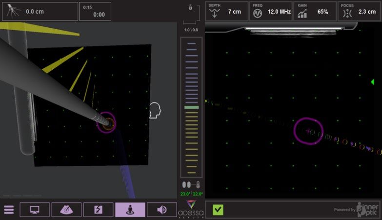
• Handpiece-ultrasound Target Zone The software provides a prediction of the Handpiece’s path and its projected
intersection point with the ultrasound scan (target zone), so the user can orient the Handpiece to the target fibroid
before inserting it. It is drawn in both the 2D and 3D views as a purple obround-shaped indicator (target zone),
superimposed over the ultrasound scan plane. The size of the obround changes with the angle of the Handpiece to the
ultrasound scan plane; when the Handpiece is perpendicular to the scan plane, the obround is a circle, and as the angle
decreases toward parallel, the obround is drawn as two lines capped with semi-circles at the ends. The Handpiece
trajectory hash marks are displayed in both the 2D and 3D views. When the hash marks are displayed as red and yellow
the Handpiece trajectory is distal to the ultrasound scan plane and when green hash marks are displayed the Handpiece
is within the ultrasound plane. The double green hash mark is representative of the Handpiece tip.
CO 20-11 Revision: B 17Acessa® ProVu System User’s Guide PL-01-0040
• Expected 3D Ablation Cage. The software can optionally display a visual indicator of the expected ablation volume at
the end of the handpiece, shown in orange. This volume guide provides the user with a 3D visual reference for physical
dimensions to further assist in electrode array placement. The dimensions and distance from the handpiece’s tip are
drawn according the tables on §12.3 and 12.4.
10.10. Procedure Planning
• The physician should determine the scope and sequence of ablations prior to starting any RF energy. Using the
ultrasound, examine the uterus and map the fibroids that are present. After all fibroids are documented, determine the
sequence of ablations and path of Handpiece insertion.
10.11. Performing an Ablation
• Locate the fibroid targeted for treatment on the ultrasound image.
• Determine the location of the tip of the Handpiece where it should enter the fibroid on the ultrasound image. Place the
tip of the Handpiece at a location on the patient’s abdomen aligned with the targeted entry point on the fibroid.
• At this point, the Guidance can be used to help confirm this location by adjusting the angle of the Handpiece so that
the trajectory lines go through the targeted area on the ultrasound image and the purple target zone lines become
visible on the image, indicating alignment with the target.
• Advance the tip of the Handpiece through the abdomen and into the abdominal cavity.
• Ensuring that the purple target zone remains located on the targeted entry point on the fibroid, advance the Handpiece
until the tip is at the serosa of the uterus viewed on the laparoscopic monitor.
• After the tip penetrates the serosa, view image on the ultrasound monitor. Corrections to the path of the tip must be
made using ultrasound imaging. Inserting the tip into the fibroid and deploying the electrode array must be done under
ultrasound visualization only.
• Continue into the fibroid until the point of the tip is approximately 1 cm into the fibroid.
• For fibroids less than 1.5 cm in diameter:
o If the fibroid is 1 cm or less, press the foot pedal (yellow) to ready the system
for an ablation, then press it again to start RF.
o If the fibroid is 1.5 cm in diameter, deploy slightly (about .2 cm) until the
expected ablation size on the screen shows a 1.5 cm ablation size. Then press
the foot pedal (yellow) to ready the system for an ablation, then press it again
to start RF.
o The ablation time will count up. When it reaches the correct time, a “Finished” tone will be heard.
o Once the tone is heard, press the foot pedal (yellow) to stop the RF energy.
WARNING: Do not advance, reposition or rotate Handpiece when electrode arrays are deployed.
• For fibroids greater than 1.5 cm in diameter:
o Deploy the electrode array until the distal point of the center needle is approximately 1 cm away from the distal
edge of the fibroid.
o Read the amount of deployment on the handpiece handle. Adjust the deployment until it is on a centimeter or
half centimeter mark.
o Confirm that the deployment displayed on the screen matches the deployment on the Handpiece handle.
o Press the Foot pedal (yellow) once to ready the system for ablation, then press again to start RF.
o The system will display the Ramp icon signifying that the temperature is rising to the target temperature of 95°C.
CO 20-11 Revision: B 18Acessa® ProVu System User’s Guide PL-01-0040
o When the temperature gets to 95°, a tone will sound signifying that target temp has been reached. The the timer
will begin to count up.
o When it reaches the correct time, a “Finished” tone will be heard.
o Once the tone is heard, press the foot pedal (yellow) to stop the RF energy.
• To shut off RF energy, depress the foot pedal (yellow).
• The most important predictor of the completeness of the ablation is having reached the desired target temperature for
the prescribed amount of time at set deployments of the electrodes of the Handpiece. For more information and
guidance, see §11 and §12.
• Retract the Handpiece’s electrode arrays and move to the next fibroid. Continue until all the fibroids have been treated.
• Immediately following a completed ablation, the user is ready to cauterize the Handpiece tract.
• When the Handpiece is removed, perform Coag as described in §9.6.
10.12. Operation of System During Coag
• Retract the Handpiece’s electrode arrays completely by sliding the electrode array knob to its mechanical stop.
• Depressing the right foot pedal (blue) activates the Ready Coag. The settings allow for 1-20 (power level), and default
is always set to 12 or the last setting chosen.
WARNING: Always verify that the electrode arrays are retracted fully before withdrawing the
Handpiece to avoid patient injury!
• The Handpiece tip should be allowed to cool for 60 seconds after the ablation has stopped prior to removing it from
the target tissue
• When ready to Coag, turn the RF energy on by pressing and holding the foot pedal (blue). The user judges proper
coagulation by visual observation and experience.
• Observe the Coag on the laparoscope and pull back the device slowly until the tip is visible.
• Turn off RF power when track coagulation is completed by releasing the foot pedal (blue).
• Note: During Coag mode the user may experience char on the tip. A sterile disposable wipe moistened with 70/30
isopropyl alcohol may be used to clean the trocar tip. Dry the Trocar or allow it to evaporate before use. Before
Handpiece insertion into peritoneal cavity, deploy electrode arrays and inspect.
10.13. After the Procedure
• Disposable items should be disposed of according to normal hospital practices. Additionally, follow local governing
ordinances and recycling plans regarding disposal or recycling of disposable items.
• Clean the non-disposable Acessa components according to the directions in §6 or in their Instructions for Use.
10.14. Shutting Down the System
• To shut down the system, press the On/Standby button for approximately 4 seconds. Then turn the switch on the rear
panel to Off (O).
CO 20-11 Revision: B 19Acessa® ProVu System User’s Guide PL-01-0040
11. Special Considerations: General Ablation Procedures
11.1. Highly Vascularized Tissue
If all connections are verified to be correct and desired temperatures continue to not be obtainable, the electrode
arrays may have been deployed into a highly vascular area. Consider withdrawing the electrode arrays (if deployed)
into the Handpiece and then rotating or repositioning the Handpiece.
11.2. One or More Electrode Arrays in a Duct or Vessel
If one or more Electrode temperatures reads much lower than the rest of the temperatures, the electrode array may
be in or near a vessel or duct. To correct this condition, stop the delivery of RF energy by depressing the foot pedal.
Fully retract the electrode arrays (if deployed), then rotate the Handpiece. Redeploy the electrode arrays, and restart
the ablation by depressing the foot pedal again.
11.3. Ablation of Dense or Calcified Fibroid Tissue
Incremental advancement of the electrode arrays will aide in penetrating dense tissue. With Console set for
temperature control and the Handpiece tip placed at the required depth for ablation, activate RF until target
temperature is reached. Deploy the electrode arrays ½ cm and maintain this deployment until target temperature is
reached. Continue with ½ cm to 1 cm deployment increments, reaching target temperature, until the last deployment
is achieved (e.g., 5 cm deployment in muscle for 12 minutes creating a final ablation size of 5.6 cm by 4.4 cm). Maintain
target temperature for stated target time for the last deployment stage to allow for complete tissue destruction.
If a fibroid is densely concentrated with calcium to the degree that there is abnormal resistance to insertion and/or
rotation of the Acessa Handpiece tip (with electrode arrays fully retracted):
o discontinue rotating the device
o withdraw the Handpiece by pulling back along the path of insertion (electrode arrays retracted, do not rotate)
o re-enter the fibroid from another direction (ideally where the sonographic appearance demonstrates
fewer/smaller calcium deposits).
Once the tip of the Handpiece is positioned in a desired location, if deployment of the electrode arrays is impeded by
calcium deposits:
o Fully retract the electrode arrays and carefully rotate the device 3-5 degrees, then re-attempt deployment (repeat
the retraction/slight rotation/deployment method if necessary until deployment is achieved).
o deployment cannot be achieved in spite of repeated efforts, fully retract the electrode arrays and attempt
deployment with the Acessa Handpiece tip repositioned in another location within the fibroid.
12. Ex-Vivo Studies
12.1. Ex-Vivo Studies
Bench top studies were conducted using Bovine liver. The purpose of these studies was to characterize the ablation
size when created with different deployments for varying amounts of time and at different power and temperature
settings. Generally, for a given time, increasing the target power or temperature tends to produce larger ablation
sizes. For a given target power or temperature, increasing the time tends to produce larger ablation sizes.
12.2. Representative Ablation Shape per Deployment
*Major dimension = length or axial length
*Minor dimension = width
CO 20-11 Revision: B 20You can also read