Performance Rating of Variable Refrigerant Flow (VRF) Multi-Split Air-Conditioning and Heat Pump Equipment - 2021 Standard for
←
→
Page content transcription
If your browser does not render page correctly, please read the page content below
AHRI Standard 1230 (I-P)

 2021 Standard for
 Performance Rating of Variable
 Refrigerant Flow (VRF) Multi-
 Split Air-Conditioning and
 Heat Pump Equipment

Approved
IMPORTANT

 SAFETY DISCLAIMER
 AHRI does not set safety standards and does not certify or guarantee the safety of any products, components or
 systems designed, tested, rated, installed or operated in accordance with this standard/guideline. It is strongly
 recommended that products be designed, constructed, assembled, installed and operated in accordance with
 nationally recognized safety standards and code requirements appropriate for products covered by this
 standard/guideline.

 AHRI uses its best efforts to develop standards/guidelines employing state-of-the-art and accepted industry
 practices. AHRI does not certify or guarantee that any tests conducted under the standards/guidelines will not
 be non-hazardous or free from risk.

 Note:

 This standard supersedes AHRI Standard 1230–2014 with Addendum 1.

 AHRI Certification Program Disclaimer

AHRI Standards are developed independently of AHRI Certification activities and may have scopes that include
products that are not part of the AHRI Certification Program. The scope of the applicable AHRI Certification
Program can be found on AHRI’s website at www.ahrinet.org.

Price $10.00 (M) $20.00 (NM) ©Copyright 2021, by Air-Conditioning, Heating, and Refrigeration Institute
Printed in U.S.A. Registered United States Patent and Trademark Office

Foreword
Major changes made from the previous version, AHRI Standard 1230-2014 with Addendum 1 are as follows

 1. Definitions have been updated to align with AHRI Standard 210/240-2017 (with Addendum 1) and DOE 10 CFR
 §429 and Appendix M to 10 CFR §430. Specific examples include Sensible Cooling Capacity, Heat Recovery
 Unit, Ducted Indoor Units, Manufacturer Instructions, Combined Modules, and Total Power.
 2. Added restrictions to maximum sensible heat ratios (SHR) at full load and 75% part-load conditions. Example
 calculations can be found in Appendix G.
 3. Reduced maximum water flow rate for water source products.
 4. Modified temperatures of water for part-load conditions.
 5. All references to systems less than 65,000 Btu/h have been removed.
 6. Updates made to the defrost controls requirements.
 7. New requirements added for VRF Air-source Systems and VRF Water-source Heat Pumps that have condenser
 head pressure controls.
 8. Updates made to manufacturer instructions requirements and handling of conflicting information during
 equipment testing.
 9. Requirements added to address different scenarios pertaining to the heating and cooling refrigerant charge.
 10. Added clarifying statements under the refrigerant piping length requirements.
 11. Modified the requirements for expressing values of system Rated Capacity rating in fixed multiples.
 12. Added clarifications in several areas of the standard on whether this standard refers to Nominal Capacity or Rated
 Capacity.
 13. Modified the Tested Combination requirements such that for ducted units, the manufacturer shall first elect to use
 the Mid-static ducted units in Tested Combinations. In addition, Nominal Capacity buckets in Table 7 have been
 expanded to < 5,500 Btu/h.
 14. Airflow-control Settings have been updated and airflow rate limitations on Ducted Indoor Units and Non-ducted
 Indoor Units (42 scfm per 1000 Btu/h and 55 scfm per 1000 Btu/h), as well as limitations to no more than 105%
 of nominal airflow as published in product literature of the individual indoor units, have been added.
 15. Static pressure difference measurements for VRF Water-source Heat Pump systems are to be conducted in
 accordance with ASHRAE 30-2019, Section 6.3.1.6.
 16. Modifications made to the test temperature conditions for VRF Water-source Heat Pump systems and for
 simultaneous heating and cooling tests.
 17. New equations added for simultaneous heating and cooling efficiency calculation.
 18. Test Operating Tolerances modified for indoor dry bulb and wet bulb temperatures (Table 12).
 19. Standard Rating Cooling Capacity uncertainty allowance reduced to ≥ 96%.
 20. Calculations have been removed from this standard. ASHRAE Standard 37 and ASHRAE handbook will be
 referenced for these calculations.
 21. Several test procedure clarifications and exceptions to ASHRAE 37-2009 have been newly identified in Appendix
 E.
 22. Unit configuration for standard efficiency determination have been modified. In addition, the requirements are
 now normative.
 23. Examples for IEER calculations based on the new IEER calculation methodology have been added in the
 informative Appendix G.
 24. An informative Appendix D with guiding instructions on developing Supplemental Testing Instructions for set-up
 and testing of VRF systems has been added.
 25. A normative Appendix C has been added on Controls Verification Procedure (CVP) to validate system controls
 operation parameters for use in steady-state tests
 26. A new “budget method” and associated calculation methods have been added to Appendix C6.1 for calculating
 variation between measured Critical Parameter values and STI-reported Critical Parameter values so that the
 maximum allowable difference is constrained
 27. An informative Appendix H has been added showing example calculations of the budget method for verifying
 Critical Parameter values listed in the STI are validated by a CVP

TABLE OF CONTENTS

SECTION PAGE

Section 1. Purpose .................................................................................................................................1

Section 2. Scope ....................................................................................................................................1

Section 3. Definitions............................................................................................................................3

Section 4. Classifications ......................................................................................................................8

Section 5. Test Requirements ...............................................................................................................8

Section 6. Rating Requirements..........................................................................................................14

Section 7. Determination of Published Ratings ..................................................................................26

Section 8. Operating Requirements ....................................................................................................27

Section 9. Marking and Nameplate Data ............................................................................................33

Section 10. Conformance Conditions ...................................................................................................33

Section 11. Calculations........................................................................................................................34

Section 12. Symbols, Subscripts and Superscripts ...............................................................................35

Section 13. Minimum Data Requirements for Published Ratings ........................................................37

Section 14. Verification Testing Acceptance Criteria ..........................................................................38

 TABLES

TABLE PAGE

Table 1. Classification of VRF Multi-split Systems ..........................................................................8

Table 2. Tolerances for Head Pressure Control Time Average Test ……………… ..................…11

Table 3. Test Condition Tolerance for Charging Hierarchy ............................................................12

Table 4. Piping Requirements from Outdoor Unit to Each Indoor Unit ..........................................13

Table 5. Refrigerant Piping Length Correction Factors at Cooling .................................................13
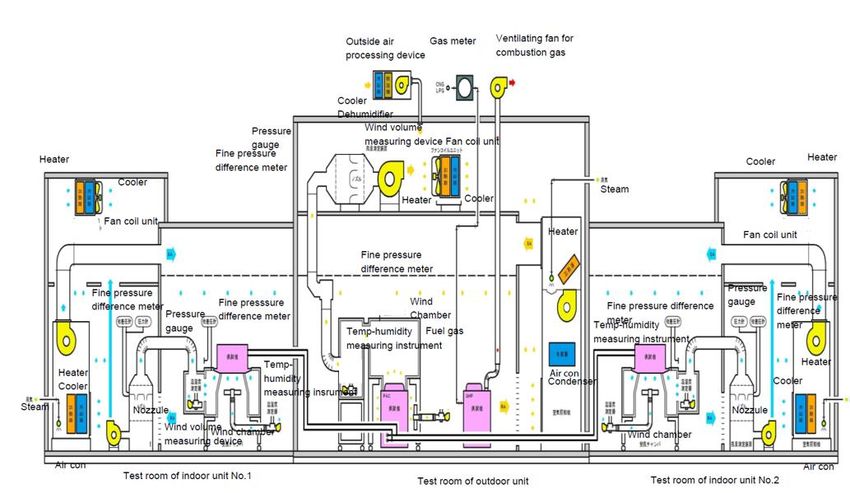
(Table of Contents continued)
TABLE PAGE

Table 6. Minimum External Static Pressure (ESP) for Individual Ducted Indoor Units .................14

Table 7. Nominal Indoor Unit Cooling Capacity Buckets ...............................................................16

Table 8. Operating Conditions for Standard Rating and Performance Operating Tests for VRF Air-
 Source Systems 20

Table 9. Operating Conditions for Standard Rating and Performance Operating Tests for the
 Determination of Cooling Capacity for VRF Water-source Heat
 Pumps………………………………………………………………………………… 23

Table 10. Operating Conditions for Standard Rating and Performance Operating Tests
 for the Determination of Heating Capacity for VRF Water-source Heat Pumps ..............23

Table 11. Simultaneous Heating and Cooling Test Conditions .........................................................24

Table 12. Test Operating Tolerances and Test Condition Tolerances ...............................................25

Table 13. Values of Full System Rated Capacity ..............................................................................26

Table 14. Statistics .............................................................................................................................26

Table 15. Maximum Cooling Test Conditions for Systems that use VRF Water-source Heat Pumps
 ............................................................................................................................................31

Table 16. Maximum Heating Test Conditions for VRF Water-source Heat Pumps .........................32

Table 17. Minimum Cooling Test Conditions for VRF Water-source
 Heat Pumps ........................................................................................................................33

Table 18. Tolerance on Part-load Percent ..........................................................................................35

Table 19. Uncertainty Allowances .....................................................................................................38

 FIGURES

FIGURE PAGE

Figure 1. Test Room Layout..............................................................................................................14

Figure 2. Voltage Tolerance Test Power Interrupt Procedure...........................................................28
(Table of Contents continued)

 APPENDICES

APPENDIX PAGE

Appendix A. References – Normative.....................................................................................................39

Appendix B. References – Informative ...................................................................................................40

Appendix C. Controls Verification Procedure - Normative ....................................................................41

Appendix D. Development of Supplemental Testing Instructions for Set-up and
 Testing – Informative .........................................................................................................46

Appendix E. ANSI/ASHRAE Standard 37–2009 Clarifications/Exceptions – Normative ....................52

Appendix F. Unit Configuration for Standard Efficiency Determination – Informative ......................70

Appendix G. Examples of IEER Calculations – Informative ..................................................................72

Appendix H. Example Calculations for Critical Parameter Budget Method – Informative....................80

 TABLES FOR APPENDICES

TABLE PAGE

Table C1. Indoor Dry Bulb Temperature Tolerances – R2 Period.………………………………..43

Table C2. Measurement Apparatus and Data Collection Intervals for CVP Parameters…………....44

Table C3. Critical Parameter Nominal Point Values………………………………..…………….....45

Table D1. Example Template for Reporting Format for Critical Parameters.....................................48

Table D2. Typical Piping for Heat Recovery System.........................................................................51

Table E1. Temperature Measurement Requirements .........................................................................53

Table E2. Criteria for Air Distribution and Control of Air Temperature ...........................................58

Table E3. Outlet Plenum Maximum Diameter ...................................................................................61

Table G1a. Example 1: Test Results.....................................................................................................72

Table G1b. Example 1: IEER Rating Points and Degradation Calculations ........................................73

Table G2a. Example 2: Test Results.....................................................................................................74
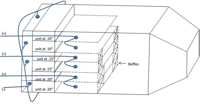
(Table of Contents continued)
TABLE PAGE

Table G2b. Example 2: IEER Rating Points and Degradation Calculations ........................................75

Table G3a. STI Reported Critical Parameter Values............................................................................75

Table G3b. Example 3: Initial Test Results ..........................................................................................76

Table G3c. Example 3: Test Results with Compressor Speed Adjustments ………………………….76

Table G3d. Example 3: Power Outputs.......………………………………………………………….77

Table G4a. STI Reported Critical Parameter Values ……………………..………………………….78

Table G4b. Example 5: Initial Test Results ……………………..……………………………………78

Table G4c. Example 5: Adjusted Test Results …...……………..……………………………………78

Table H1. STI Reported Critical Parameter Values .…………..……………………………………80

Table H2. 75% Instantaneous Parameter Variation Calculation.……………………………………80

Table H3. Instantaneous Parameter Point Calculation………....……………………………………80

Table H4. Measurement Period Point Total Average ………....……………………………………81

 FIGURES FOR APPENDICES

FIGURE PAGE

Figure C1. Controls Verification Procedure Schematic……………………………………………...42

Figure D1. Typical Wiring Diagram for Heat Pump ...........................................................................49

Figure D2. Typical Wiring Diagram for Heat Recovery System.........................................................50

Figure D3. Typical Piping Diagram for Heat Recovery System..........................................................50

Figure E1. Typical Air Sampling Tree ................................................................................................54

Figure E2. Aspirating Psychrometer....................................................................................................55

Figure E3. Single Module Air Sampling Tree Placement Example ....................................................59

Figure E4. Multiple Module Air Sampling Tree Placement Example ................................................59

Figure E5. Typical Configuration for Manifolding the Static Pressure Taps ......................................62
(Table of Contents continued)
FIGURE PAGE

Figure E6. Typical Setup for Wall Mounted Indoor Units ..................................................................65

Figure E7a. Typical Indoor Units Installation Based on Different Static Pressures .............................66

Figure E7b. Typical Indoor Units Installation for IDUs of Same Chassis Size ....................................66

Figure E7c. Typical Indoor Units Installation for IDUs of Different Chassis Size...............................67

Figure E8. Schematic of Typical Test Setup for Ducted Indoor Units with Common Duct ...............67

Figure E9a. Typical Return Air Measurement Setup For Non-Ducted Units, Sampling Tree at Unit 68

Figure E9b. Typical Return Air Measurement Setup For Non-Ducted Units, Sampling Tree
Common ............................................................................................................................................68

Figure E10. Typical Return Air Measurement Setup For Ceiling Cassette...........................................68

Figure E11. Typical VRF Setup in Laboratory......................................................................................69
AHRI STANDARD 1230 (I-P)-2021

 PERFORMANCE RATING OF VARIABLE REFRIGERANT
FLOW (VRF) MULTI-SPLIT AIR-CONDITIONING AND HEAT
 PUMP EQUIPMENT
 Section 1. Purpose

1.1 Purpose. The purpose of this standard is to establish for Variable Refrigerant Flow (VRF) Multi-split Air Conditioners
and Heat Pumps: definitions; classifications; test requirements; rating requirements; determination of Published Ratings;
operating requirements; marking and nameplate data; conformance conditions; minimum data requirements for Published
Ratings and calculations.

 1.1.1 Intent. This standard is intended for the guidance of the industry, including manufacturers, engineers, installers,
 contractors and users.

 1.1.1.1 Specific interests include, but are not limited to, federal regulations, state regulations and efficiency
 standards developed by ASHRAE, International Energy Conservation Code (IECC), Canadian Standards
 Association (CSA), and United States Department of Energy (DOE).

 1.1.2 Review and Amendment. This standard is subject to review and amendment as technology advances.

 Section 2. Scope

2.1 This standard applies to Variable Refrigerant Flow (VRF) Multi-split Air Conditioners and Multi-split Heat Pumps using
distributed refrigerant technology, including all capacities of VRF Water-source Heat Pump systems and VRF Air-source
systems with cooling capacity ≥ 65,000 Btu/h, as defined in Section 3 and referenced as the “Basic Model”.

Note: In the event that this standard is required to demonstrate regulatory compliance, stakeholders must abide by all published
requirements applicable to the regulated product. For example, for products that contain one or more design characteristics
which either prevent testing according to this standard or cause this standard to evaluate the equipment in a manner
unrepresentative of its true energy consumption characteristics, DOE requires the manufacturer to submit a petition for waiver,
which would include an alternative method of test.

2.2 This standard applies to Variable Refrigerant Flow (VRF) Systems defined in 3.47.

2.3 Exclusions. This standard does not apply to the rating and testing of:

 • Individual assemblies, such as separate condensing units or indoor units;
 • Air-conditioners and Heat Pumps, with capacities less than 65,000 Btu/h as defined in AHRI Standard 210/240;
 • Water-source Heat Pumps (with the exception of Multi-split Systems) as defined in AHRI/ASHRAE ISO Standard
 13256-1;
 • Unitary Air-conditioners and Unitary Heat Pumps as defined in AHRI Standard 340/360, with capacities ≥65,000
 Btu/h;
 • Units equipped with desuperheater/water heating devices as defined in AHRI Standard 470;
 • Commercial and Industrial Condensing units with a capacity greater than 135,000 Btu/h as defined in AHRI
 Standard 365 (I-P);

2.4 Energy Source. This standard applies only to electrically operated, vapor compression refrigeration systems.

 Section 3. Definitions

All terms in this document will follow the standard industry definitions in the ASHRAE Terminology website
(https://www.ashrae.org/resources--publications/free-resources/ashrae-terminology) unless otherwise defined in this section.

 1
AHRI STANDARD 1230 (I-P)-2021

Note: For the purpose of this standard, the terms “equipment” and “systems” are used throughout to mean Multi-split Air-
conditioners and/or Multi-split Heat Pumps unless otherwise specified.

3.1 Acronyms.

 3.1.1 AHRI. Air-Conditioning, Heating, and Refrigeration Institute.
 3.1.2 CFR. Code of Federal Regulations.

3.2 Air Sampling Device(s). A combination of Air Sampling Tree(s), conduit, fan and Aspirating Psychrometer or Dew-
point Hygrometer used to determine dry-bulb temperature and moisture content of an air sample from critical locations.

 3.2.1 Air Sampling Tree. An assembly consisting of a manifold with several branch tubes with multiple sampling
 holes that draws an air sample from a critical location from the unit under test (e.g. indoor air inlet, indoor air outlet,
 outdoor air inlet, etc.).

 3.2.2 Aspirating Psychrometer. An instrument used to determine the humidity of air by simultaneously measuring
 both the wet-bulb and dry-bulb temperatures. The difference between these temperatures is referred to as the wet-bulb
 depression.

 3.2.3 Dew-point Hygrometer. An instrument used to determine the humidity of air by detecting visible condensation
 of moisture on a cooled surface.

3.3 Airflow-control Setting(s). Programmed or wired control system configurations that control a fan to achieve discrete,
differing ranges of airflow—often designated for performing a specific function (e.g., cooling, heating, or constant
circulation)—without manual adjustment other than interaction with a user-operable control (i.e., a thermostat) as specified in
Manufacturer’s Installation Instructions.

3.4 Approach Temperature. The refrigerant temperature at the outdoor liquid service port minus the outdoor ambient
temperature.

3.5 Basic Model. All units manufactured by one manufacturer within a single equipment class and which have the same or
comparably performing compressor(s) that have a common “nominal” cooling capacity and the same heat rejection medium
(e.g., air or water).

3.6 Capacity.

 3.6.1 Heating Capacity. The rate of heat that the equipment adds to the conditioned space or heat transfer fluid in a
 defined interval of time, Btu/h.

 3.6.2 Latent Cooling Capacity. The rate at which the equipment reduces the moisture content (removes latent heat)
 of the air passing through it under specified conditions of operation, Btu/h.

 3.6.3 Nominal Cooling Capacity. Nominal Capacity may be referred to using the following terms:

 3.6.4 Percent Load. The ratio of the part-load Cooling Capacity over the measured full load Cooling Capacity at
 Standard Rating Conditions, expressed in units of percent, %.

 3.6.5 Rated Capacity. The capacity achieved at the Standard Rating Conditions, Btu/h.

 3.6.5.1 Standard Rating Cooling Capacity. The capacity of the system when all Indoor Units and Outdoor
 Units are all operated in cooling mode, in the Standard Rating Conditions Cooling, Btu/h.

 3.6.5.2 Standard Rating Heating Capacity. The capacity of the system when all Indoor Units and Outdoor
 Units are operated in heating mode, in the Standard Rating Conditions (High Temperature Heating Steady-state
 Test and Low Temperature Heating Steady-state Test), Btu/h.

2
AHRI STANDARD 1230 (I-P)-2021

 3.6.6 Sensible Cooling Capacity. The rate at which the equipment lowers the dry-bulb temperature (removes sensible
 heat) of the air passing through it under specified conditions of operation, Btu/h.

 3.6.7 Total Cooling Capacity. The sum of Sensible Cooling Capacity and Latent Cooling Capacity, under specified
 conditions of operation, Btu/h.

 3.6.7.1 Nominal Cooling Capacity (for Indoor Unit and Outdoor Unit). Nominal Cooling Capacity where
 referenced, is the approximate cooling capacity tested at Standard Rating Conditions, as published in product
 literature, Btu/h.

3.7 Coefficient of Performance (COPH). A ratio of the Heating Capacity in watts to the power input in watts at any given
set of Rating Conditions, W/W.

 3.7.1 Coefficient of Performance at High Temperature (COPH). The Coefficient of Performance obtained at the 47
 ⁰F temperature Rating Condition. For COPH, supplementary resistance heat shall be excluded.

 3.7.2 Coefficient of Performance at Low Temperature (COPL). The Coefficient of Performance obtained at the 17
 ⁰F temperature Rating Condition.

3.8 Connected Capacity. The sum of the Nominal Capacity of Indoor Units as a percent of Standard Rated Cooling Capacity,
Btu/h.

3.9 Control Setting(s). System configurations specified in the Manufacturer’s Installation Instructions and Supplemental
Testing Instructions.

3.10 Controls Verification Procedure (CVP). The procedure outlined in Normative Appendix C of this standard that is
intended to verify the Control Settings for Critical Parameters used during the Steady-state Test.

3.11 Critical Parameter(s). Key variables affecting the measured result. Any operating state or position for a component,
either set manually or automatically by System Controls, which significantly impacts system performance.

3.12 Degradation Coefficient (CD). A parameter used in calculating the part-load factor, which is a measure of the efficiency
loss due to the cycling of the units.

3.13 Energy Efficiency Ratio (EER). A ratio of the cooling capacity in Btu/h to the Total Power in watts at any given set of
Rating Conditions, (Btu/h)/W.

 3.13.1 Integrated Energy Efficiency Ratio (IEER). A weighted calculation of mechanical cooling efficiencies at full
 load and part-load Standard Rating Conditions, as outlined in Section 11, (Btu/h)/W.

3.14 Heat Pump(s). A kind of central air conditioner(s) that utilizes an indoor conditioning coil, compressor, and refrigerant-
to-outdoor air heat exchanger to provide air heating, and may also provide air cooling, air dehumidifying, air humidifying, air
circulating, and air cleaning.

3.15 Heat Recovery Control Unit. A device that controls refrigerant flow between Indoor Units, allowing for simultaneous
cooling and heating operation.

3.16 Indoor Unit. A separate assembly of a Split System (a service coil is not an Indoor Unit) that includes the features listed
below:

 • An arrangement of refrigerant-to-air heat transfer coil(s) for transfer of heat between the refrigerant and the indoor
 air;
 • A condensate drain pan;
 • An air temperature sensing device; and
 • An integrated indoor blower (i.e. a device to move air including its associated motor).

 3
AHRI STANDARD 1230 (I-P)-2021

An Indoor Unit may or may not include the features listed below:
 • Sheet metal or plastic parts not part of external cabinetry to direct/route airflow over the coil(s);
 • A cooling mode expansion device; and
 • External case.

For the purpose of this standard, Indoor Units are categorized into two subparts:

 3.16.8 Ducted Indoor Unit. An Indoor Unit designed to be permanently installed and deliver all conditioned air
 through ductwork.

 3.16.9 Non-ducted Indoor Unit. An Indoor Unit designed to be permanently installed, mounted on room walls, floors
 and/or ceilings, which directly heats or cools air within the conditioned space. Non-ducted Indoor Units consists of the
 following types: Wall-mounted, Floor-mounted, Ceiling-suspended, Standard 4-way Ceiling Cassette and Compact 4-
 way Ceiling Cassette.

3.17 Indoor Unit Model Family. A group of indoor unit models consisting exclusively of the same kind of indoor units, as
specified in 3.17.1, 3.17.2 and 3.17.3 below.

 3.17.1 Non-ducted Indoor Unit Model Families.

 3.17.1.1 Ceiling-suspended. A non-ducted Indoor Unit that is totally encased and is suspended below the
 ceiling.

 3.17.1.2 Floor-mounted. A non-ducted Indoor Unit intended for being installed at floor level either enclosed
 in the wall space in an uncased configuration or extended out from the wall in a cased configuration.

 3.17.1.3 Ceiling Cassette. Non-ducted Indoor Units intended to be installed flush mounted with the ceiling.
 These Indoor Units can have configurations of indoor airflow coming from one, two, four, or circular
 direction(s). Each of the following represents a separate Indoor Unit Model Family.

 3.17.1.3.1 Compact 4-way Ceiling Cassette. A Ceiling Cassette with air discharge louvers on 4
 or more sides (or circular), a central air return grill and main casing dimensions less than 32 in x 32
 in (not including flanges).

 3.17.1.3.2 One-way Cassette. A Ceiling Cassette with air discharge louvers on a single side.

 3.17.1.3.3 Standard 4-way Ceiling Cassette. A Ceiling Cassette with air discharge louvers on 4
 or more sides (or circular), a central air return grill and main casing dimensions greater than, or
 equal to, 32 in x 32 in (not including flanges).

 3.17.1.3.4 Three-way Cassette. A Ceiling Cassette with air discharge louvers on three sides.

 3.17.1.3.5 Two-way Cassette. A Ceiling Cassette with air discharge louvers on two sides.

 3.17.1.4 Wall-mounted. A non-ducted Indoor Unit that is attached to the wall with a cased configuration,
 sometimes referred to as a high-wall unit.

 3.17.2 Ducted Indoor Unit Model Families. Model families when operated at the full-load cooling airflow that
 produces the following ESP range:

 3.17.2.1 Low-static. A ducted Indoor Unit that produces ESP between 0.01 and 0.35 in H 2O of external static
 pressure (ESP).

 3.17.2.2 Mid-static. A ducted Indoor Unit that produces ESP between 0.20 and 0.65 in H 2O of external
 static pressure (ESP).

4
AHRI STANDARD 1230 (I-P)-2021

 Note: If the Indoor Unit model grouping in manufacturer’s publicly available literature is not in accordance with Section
 3.17.2, Section 3.17.2 shall take precedence for the determination of Tested Combinations.

 If the range of ESP, as published in manufacturer’s publicly available literature, for an Indoor Unit falls within the ESP
 range for more than one type of Ducted System, then the Indoor Unit shall be classified based on where the majority of
 the ESP capability lies.

 If an Indoor Unit can operate between 0.15 in H 2O and 0.65 in H2O, then this Indoor Unit is considered to be a Mid-
 static Indoor Unit. Also, if an Indoor Unit can operate between 0.35 in H2O and 0.75 in H2O, then this Indoor Unit is
 considered to be a Mid-static Indoor Unit.

 3.17.3 Small-duct, High-velocity (SDHV) Indoor Unit Model Family. An Indoor Unit designed to be permanently
 installed and deliver all conditioned air through ductwork and that produces at least 1.2 in H2O of ESP when operated
 at the full-load cooling airflow of at least 220 scfm per ton of Nominal Cooling Capacity. The Small-duct, High-velocity
 Indoor Unit Model Family is a unique Indoor Unit Model Family Type that is not one of the Ducted Indoor Unit Model
 Families.

3.18 Manufacturer’s Installation Instructions (MII). Manufacturer’s documents that come packaged with or appear in the
labels applied to the unit(s). Online manuals are acceptable if referenced on the unit label or in the documents that come
packaged with the unit. All references to “manufacturer’s instructions,” “manufacturer's published instructions,”
“manufacturer’s installation instructions,” “manufacturer’s published recommendations,” “manufacturer installation and
operation manuals,” “installation instructions”, “manufacturer-specified”, and other similar references means Manufacturer’s
Installation Instructions.

 3.18.1 Supplemental Testing Instructions (STI). Additional instructions developed by the manufacturer for the purpose
 of being able to test a VRF System to this test standard. Refer to Section 5.4.1 for STI requirements.

3.19 Nominal Point Value. The value corresponding to a 1% variation in the given critical parameter. Refer to Table C3 for
individual parameter values

3.20 Oil Recovery Mode. An automatic system operation that returns oil to the compressor crankcase when the control system
determines that the oil level in the Outdoor Unit is low.

3.21 Outdoor 2-position Valves. Two-position refrigerant valves in the Outdoor Unit.

3.22 Outdoor Unit. A separate assembly of a Split System that transfers heat between the refrigerant and the outdoor air or
refrigerant and water, and consists of an outdoor heat exchanger, compressor(s), an air moving device, and in addition for Heat
Pumps, may include a heating mode expansion device, reversing valve, and/or defrost controls; VRF Water-source Heat Pumps
may not have an air movement device. An Outdoor Unit can be either Single Module or Combined Modules.

 3.22.1 Combined Modules. Two (2) or more Single Modules that are mechanically and electronically joined together
 to operate as a single Outdoor Unit that is assembled with multiple Indoor Units to form a system. When such equipment
 is provided in more than one assembly, the separated assemblies shall be designed to be used together, and the
 requirements of rating outlined in the standard are based upon the use of matched assemblies.

 3.22.2 Single Module. A single Outdoor Unit that is assembled with multiple Indoor Units and controls to form a
 system.

3.23 Outdoor Variable Valves. Variable position refrigerant valves in the Outdoor Unit.

3.24 Published Rating. A statement of the assigned values of those performance characteristics, under stated Rating
Conditions, by which a unit may be chosen to fit its application. These values apply to all units of like nominal size and type
(identification) produced by the same manufacturer. As used herein, the term Published Rating includes the rating of all
performance characteristics shown on the unit or published in specifications, advertising or other literature controlled by the
manufacturer, at stated Rating Conditions.

 3.24.1 Application Rating. A rating based on tests performed at application Rating Conditions (other than Standard
 Rating Conditions).
 5
AHRI STANDARD 1230 (I-P)-2021 3.24.2 Standard Rating. A rating based on tests performed at Standard Rating Conditions. 3.25 Rating Conditions. Any set of operating conditions under which a single level of performance results and which causes only that level of performance to occur. 3.25.1 Standard Rating Conditions. Rating Conditions used as the basis of comparison for performance characteristics. 3.26 Return Air Temperature Unit Sensor(s). A factory installed component that measures the temperature of the return air or indoor room air entering the unit under test. 3.27 RSS Point Total. An instantaneous measure of Critical Parameter variation, the root-sum-square of the points accrued by all overridden critical parameters, as defined by equation C5. 3.28 Sensible Heat Ratio (SHR). A ratio of the Sensible Cooling Capacity to the Total Cooling Capacity at a given condition. 3.29 Set Point Bias. The difference between 80ºF and the nominal thermostat set point required for the thermostat to control for 80ºF sensed temperature at the sensed location. 3.30 Set Point Offset. The difference between the temperature indicated by a thermostat’s temperature sensor and the actual temperature at the sensor’s location. 3.31 Service Tool. A manufacturer’s service tool for checking system hardware/software, typically available for download from manufacturer’s certified installer website or from an authorized representative. 3.32 “Shall” or “Should”. “Shall” or “should” shall be interpreted as follows: 3.32.1 Shall. Where “shall” or “shall not” is used for a provision specified, that provision is mandatory if compliance with the standard is claimed. 3.32.2 Should. “Should” is used to indicate provisions which are not mandatory but which are desirable as good practice. 3.33 Simultaneous Cooling and Heating Efficiency (SCHE). The ratio of the total capacity of the system (heating and cooling capacity) to the Total Power when operating in the heat recovery mode, (Btu/h)/W. 3.34 Small-duct, High-velocity System (SDHV). Split System for which all Indoor Units are SDHV Indoor Units. 3.35 Stable Conditions. Balanced operating conditions in the indoor and outdoor section of the test chamber where the test unit is maintaining Steady-state Test conditions and the test chamber is maintaining test room conditions within prescribed tolerances. 3.36 Standard Air. Air weighing 0.075 lb/ft3 which approximates dry air at 70 F and at a barometric pressure of 29.92 in Hg. 3.37 Standard Airflow. The volumetric flowrate of air corrected to standard air conditions, in scfm. 3.38 Standard Rating Test. Tests performed at Standard Rating Conditions. 3.39 Steady-state Test. A test where the controlled test parameters are regulated to remain within the specified tolerances while the unit operates continuously in the same mode. 3.40 System Controls. The following items characterize System Controls: • An integral network operations and communications system with sensors to monitor and forecast the status of items such as temperature, pressure, oil, refrigerant levels and fan speed. • A microprocessor, algorithm-based control scheme to: (1) optimally manage Compressor(s), fan speed of Indoor Units, fan speed of the Outdoor Unit, solenoids, various accessories; (2) manage metering devices; and (3) concurrently operate various parts of the system. 6
AHRI STANDARD 1230 (I-P)-2021

 • Optimize system efficiency and refrigerant flow through an engineered distributed refrigerant system to conduct
 zoning operations, matching capacity to the load in each of the zones.

3.41 Test Condition Tolerance. The maximum permissible difference between the average value of the measured test
parameter and the specified test condition.

3.42 Test Operating Tolerance. The maximum permissible range a measurement may vary over the specified test interval.
When expressed as a percentage, the maximum allowable variation is the specified percentage of the average value. The
difference between the maximum and minimum sampled values shall be less than or equal to the specified Test Operating
Tolerance.

3.43 Tested Combination. An arrangement of Indoor Units and Outdoor Units that are production units (or for product
development purposes are representative of production units) and provides representative performance values. The
requirements for Tested Combination are stated in Section 6.2.

3.44 Thermally Active. The state of an Indoor Unit in which it is cooling, as indicated by the digital on/off signal from the
Service Tool or by an EEV position indicated by the Service Tool greater than the minimum EEV position for that valve.

3.45 Thermally Inactive. The state of an Indoor Unit in which it is not Thermally Active.

3.46 Total Power. The sum of the average electrical power input consumed by all components of a system, including, W:

 • Power input for operation of the compressor(s);
 • Power input to electric heating devices used only for defrosting;
 • Power input to all control and safety devices of the equipment;
 • Power input to factory installed condensate pumps; and
 • Power input for operation of all fans and, if applicable, any Water-source condenser pump(s) (including pump
 power adjustments).

3.47 Variable Refrigerant Flow (VRF) System. An engineered direct expansion (DX) air-conditioning or Heat Pump multi-
split systems incorporate the characteristics and components of 3.47.1.

Note: VRF Systems less than 65,000 Btu/h are considered as central air conditioners and central air conditioning Heat Pumps
in 10 CFR §429, 10 CFR §430 and 10 CFR §431.

 3.47.1 VRF Systems characteristics and components are as follows:

 • A single refrigerant circuit that has a common piping network to multiple Indoor Units;
 • Single Module or Combined Module Outdoor Units;
 • Two (2) or more Indoor Units;
 • Three or more steps of capacity; and
 • A zone temperature control device (i.e. thermostat).

 3.47.2 VRF Air-source System. A VRF Heat Pump with Single Module or Combined Module Outdoor Units that have
 air-to-refrigerant heat exchangers.

 3.47.3 VRF Heat Recovery System. A VRF Air-Source System or VRF Water-source Heat Pump that is capable of
 providing simultaneous heating and cooling operation via a Heat Recovery Control Unit, where recovered energy from
 the Indoor Units operating in one mode can be transferred to one or more other Indoor Units operating in the other mode.

 Note: This may be achieved by a gas/liquid separator or a third line in the refrigeration circuit.

 3.47.4 VRF Water-source Heat Pump. The Heat Pump consists of one or more factory-made assemblies which
 normally include an indoor conditioning coil with air moving means, compressor(s) and refrigerant-to-fluid heat

 7
AHRI STANDARD 1230 (I-P)-2021

 exchanger(s), including means to provide both cooling and heating functions. Any references to VRF Water-source Heat
 Pumps in this Standard includes all capacities. The four main types of VRF Water-source Heat Pumps are as follows:

 3.47.4.1 Ground-loop Heat Pump. Brine-to-air Heat Pump using a brine solution circulating through a
 subsurface piping loop functioning as a heat source/heat sink.

 Note: The heat exchange loop may be placed in horizontal trenches, vertical bores, or be submerged in a
 body of surface water. The temperature of the brine is related to the climatic conditions and may vary from
 23ºF to 104ºF.

 3.47.4.2 Ground-water Heat Pump. Water-source Heat Pump using water pumped from a well, lake, or
 stream functioning as a heat source/heat sink.

 Note: The temperature of the water is related to the climatic conditions and may vary from 41ºF to 77ºF for
 deep wells.

 3.47.4.3 Water Loop Heat Pump. Water-source Heat Pump using liquid circulating in a common piping loop
 as a heat source/heat sink.

 Note: The temperature of the liquid loop is usually controlled within a temperature range of 59°F to 104°F.

3.48 Variable Speed Compressor. A compressor that has capability of varying its rotational speed in non-discrete stages or
steps from low to intermediate to full using an inverter or variable frequency drive.

 Section 4. Classifications

4.1 Equipment covered within the scope of this standard shall be classified as shown in Table 1.

 Table 1. Classification of VRF Systems
 VRF
 VRF Heat Recovery
 System Identification Air-conditioner or
 System
 Heat Pump System
 Air-conditioner (Air-source) MSV-A-CB1 Not Applicable
 Air-conditioner (Water-source) Not Applicable Not Applicable
 Heat Pump (Air-source) HMSV-A-CB 1 HMSR-A-CB1
 Heat Pump (Water-source) HMSV-W-CB 1 HMSR-W-CB1
 Notes:
 1. “-A” indicates Air-source condenser and “-W” indicates Water-source condenser.

 Section 5. Test Requirements

5.1 All testing for Standard Ratings shall be conducted in accordance with the test methods and procedures as described in
this standard and its appendices.

 5.1.1 VRF Systems shall be tested in accordance with AHRI Standard 1230 Section 6, AHRI Standard 1230
 Appendix C, ASHRAE Standard 37 with clarifications in AHRI Standard 1230 Appendix E, AHRI Standard 1230
 Appendix G. VRF Water-source Heat Pump systems shall additionally be tested in accordance with ASHRAE 30 Section
 6.3.1.6.

 5.1.2 To set up equipment for test, manufacturer authorized personnel with knowledge of the control software may
 support commissioning of the system being tested.

 5.1.2.1 The system shall operate per commands from the System Controls except that the Critical Parameter(s)
 listed below shall be allowed to be manually overridden. Operational settings for Critical Parameters shall be

8
AHRI STANDARD 1230 (I-P)-2021

 as specified in STI and with RSS Point Total ≤ 70 points as defined in section C6.

 • Compressor Speed(s);
 • Outdoor Fan Speed(s); and
 • Outdoor Variable Valve Position(s).

 For a given system, a maximum of three Critical Parameter(s) options listed above shall be permitted to be
 overridden. Multiple individual parameters of a group may be overridden.

 5.1.2.2 All compressors shall initially operate at the speed or setting(s) provided in the STI. Additional
 adjustments to compressor speed for the purpose of achieving capacity targets or meeting SHR limits are
 allowed so long as conditions outlined in section 6.3.3 are met. During part-load tests, where more than one
 compressor is present, the compressors can only be stopped if the manufacturer’s operating System Controls
 would cause that mode of operation in the field.

 5.1.2.3 Control Settings. Control Settings shall be set by a member of the Laboratory. All Control Settings are
 to remain unchanged for all load points once system set up has been completed. Component operation shall be
 controlled by the unit under test once the provisions in Section 6 are met.

 5.1.2.3.1 Airflow-control Setting(s). These settings shall be in accordance with Section 6.

 5.1.2.4 If the Thermally Active state of an indoor unit cannot be determined from the digital on/off signal
 available from the Service Tool, active status is indicated by an EEV position indicated by the Service Tool
 greater than the minimum EEV position for that valve. The time history of the temperature difference between
 the inlet and outlet thermocouple grids of an indoor unit may be examined to confirm either of these indication
 methods.

5.1.3 Oil Recovery Mode. The Oil Recovery Mode shall be enabled during testing. If Oil Recovery Mode prevents a
Steady-state Test, use the transient test procedure as described in Section 8.8.3 (except Section 8.8.3.3) of ASHRAE
Standard 37, with the revisions in the following section:

 5.1.3.1 For tests of VRF Air-source Systems that cannot reach steady-state because of Oil Recovery Mode,
 Section 8.8.3 (except Section 8.8.3.3) of ASHRAE Standard 37 shall be modified by replacing all mentions of
 “defrost” with “Oil Recovery Mode”, replacing all mentions of “Heat Pump” with “system” and replacing all
 mentions of “heating” with “conditioning”. The test tolerances specified in Table 2 of ASHRAE Standard 37
 for “heat portion” under “heat with frost” must be satisfied when conducting the tests. The test tolerance
 parameters included in Table 2 of ASHRAE Standard 37 must be sampled throughout the preconditioning and
 data collection period. For the purpose of evaluating compliance with the specified test tolerances, the dry-bulb
 temperature of the air entering the indoor-side and the outdoor-side, and the water vapor content of the air
 entering the indoor or outdoor-side must be sampled at least every minute. All other parameters must be
 sampled at equal intervals that span five minutes or less.

5.1.4 Defrost Controls. Defrost controls shall be left at manufacturer’s factory settings if the MII provided with the
equipment do not specify otherwise. Any Control Settings for defrost specified by the MII which can be achieved through
methods outlined in the MII may be used to achieve Steady-state Test operation. If unable to run a Steady-state Test
procedure due to Control Settings for defrost, the transient test procedure as defined in ASHRAE Standard 37 shall be
used with the following exceptions: 1. The Test Operating Tolerance for the outdoor entering conditions are omitted
during the defrost portion. 2. The Test Operating Tolerances and Test Condition Tolerances for the heat portion shall
apply when the unit is in heating mode except for the first 30 minutes after terminating a defrost cycle. To facilitate
testing of any unit, the manufacturer shall provide information and any necessary hardware to manually initiate a defrost
cycle.
5.1.5 Indoor Unit Temperature Control Set Point. The temperature set point for each Indoor Unit which is Thermally
Active shall be set to 80 °F.

 5.1.5.1 Identify and correct for Set Point Offset(s) that may be present in indoor unit thermostats by using the
 following procedures. Round set point adjustments to the nearest set point increment.

 9
AHRI STANDARD 1230 (I-P)-2021

 5.1.5.1.1 If the control for the Indoor Unit utilizes an independent return/indoor ambient air
 temperature unit sensor for each Indoor Unit, for each Indoor Unit adjust the set point by the difference
 between the measurements of the return air thermocouple grid and the Return Air Temperature Unit
 Sensor (the latter determined using either the on-board thermostat reading or the Service Tool).

 5.1.5.1.2 If the Indoor Unit control utilizes a common Return Air Temperature Unit Sensor for
 multiple Indoor Units in operation, make a single adjustment by the difference between the average of
 the thermocouple grid measurements and the Indoor Units group’s return/ambient air temperature
 sensor (determined using either the on-board thermostat reading or from the Service Tool).

 5.1.5.2 If the controls of the unit under test include a Set Point Bias, the manufacturer may include the Set
 Point Bias in the STI. If a Set Point Bias is included in the STI, the temperature set point for each Indoor Unit
 which is Thermally Active shall be set to 80°F, less the STI-reported Set Point Bias up to 2°F. If the controls
 have a Set Point Bias and there is also Set Point Offset, the temperature set point for each Indoor Unit which
 is Thermally Active shall be set to 80°F, less the STI-reported Set Point Bias (up to 2°F), plus the difference
 between the thermocouple grid measurement (or average) and the Return Air Temperature Unit Sensor.

5.2 Head Pressure Control for VRF Air-source Systems and VRF Water-source Heat Pump Systems. For units that have
condenser head pressure control to ensure proper flow of refrigerant through the expansion valve during low condenser air or
water inlet temperature conditions, the head pressure controls shall be enabled and operate in automatic control mode. The
setting should be set at the factory settings or as defined in the MII.

If the head pressure control is engaged by the control logic during part-load cooling tests, then use the following steps. For all
part-load cooling tests for VRF Water-source Heat Pump systems, the water flow rate must not exceed the value for the full-
load cooling test.

 5.2.1 Allow the control logic to control the operation of the unit. If the unit can be run and Stable Conditions are
 obtained (e.g., test tolerances in Table 15 are met), then a standard part-load cooling test shall be run.

 5.2.2 Head Pressure Control Time Average Test. If the head pressure control results in unstable conditions (e.g., test
 tolerances in Table 15 cannot be met), then a series of two 1-hour Steady-state Tests shall be run. Prior to the first 1-
 hour test the condenser entering temperature (e.g., outdoor air dry-bulb temperature or condenser water temperature)
 defined by Table 8 or 9 (as applicable) shall be approached from at least a 10ºF higher temperature until the tolerances
 specified in Table 2 are met. Prior to the second 1-hour test, the condenser entering temperature defined by Table 8 or
 9 (as applicable) must be approached from at least a 5ºF lower temperature until the tolerances specified in Table 2 are
 met. For each test, once all tolerances in Table 2 are met, the 1-hour test shall be started and test data shall be recorded
 every 5 minutes for 1 hour, resulting in 12 test measurements for each test parameter. During each 1-hour test, the
 tolerances specified in Table 2 must be met.

 If the tolerances in Table 2 are met, the test results for both 1-hour Steady-state Tests shall then be averaged to determine
 the capacity and efficiency that is then used for the IEER calculation.

10
AHRI STANDARD 1230 (I-P)-2021

 Table 2. Tolerances for Head Pressure Control Time Average Test
 Operating Tolerance Condition Tolerance
 Indoor air dry-bulb Entering 3.0 1.0
 temperature (°F) Leaving 3.0 -
 Indoor air wet-bulb Entering 1.5 0.5
 temperature (°F) Leaving 1.5 -
 Outdoor air dry-bulb Entering 3.0 1.0
 temperature (°F) Leaving - -
 Outdoor air wet-bulb Entering 1.5 -
 temperature (°F) Leaving - -
 Water serving outdoor coil Entering 0.75 0.3
 temperature (°F) Leaving 0.75
 Voltage 2% 1%

 5.2.3 If the tolerances in Table 2 cannot be met for the head pressure control time average test, MII shall be used to
 determine the settings required to stabilize operation. However, if MII do not provide guidance for stable operation or
 result in a condensing (liquid outlet) pressure corresponding to a bubble point temperature less than 75°F, proceed to
 5.2.4.

 5.2.4 If MII cannot be used to achieve stable operation, the fan(s) (for Air-Source units) or valve(s) (for VRF Water-
 source Heat Pump systems) causing the instability shall be set manually at a speed, operating state (on/off), or position
 to achieve a condensing (liquid outlet) pressure corresponding to a bubble point temperature as close to 85°F as possible
 while remaining no lower than 85°F.

5.3 Instruments.

 5.3.1 Use instruments that meet the applicable requirements specifications in Section 5 of ASHRAE Standard 37
 with the amendments in Sections 5.3.2 and 5.3.3.

 5.3.2 For measurement of indoor and outdoor air temperatures, the provisions of Appendix E4 applicable to
 instruments take precedence over Section 5 of ASHRAE Standard 37.

 5.3.3 The atmospheric pressure measuring instruments must be accurate to within ±0.5% of the reading.

5.4 Literature Hierarchy. For system set-up and Control Settings, use specifications from the STI. For instructions not
specified in the STI, hierarchy shall be Outdoor Unit MII, followed by the Outdoor Unit labels, followed by the Indoor Unit
MII. For settings not specified in any of the preceding sources, the as-shipped setting shall be used.

 5.4.1 STI shall include the following:

 5.4.1.1 All instructions that do not deviate from MII but provide additional specifications for test standard
 requirements allowing more than one option; and

 5.4.1.2 Documentation of settings and software required to obtain all deviations from MII necessary to comply
 with Steady-state Test requirements.

 STI shall provide steady operation that matches to the extent possible the average performance that would be obtained
 without deviating from the MII. STI shall include no instructions that deviate from MII other than those described in
 5.4.1.2 above.

5.5 Test Unit Location. All Indoor Unit(s) and VRF Water-source Heat Pump Outdoor Unit(s) must be located in an indoor
test room(s) (i.e., a test chamber(s) maintained at the air conditions specified for return indoor air) during all tests. VRF Air-
source System Outdoor Unit(s) must be located in the outdoor test room(s) (i.e., the test chamber(s) maintained at the air
conditions specified for outdoor ambient air) during all tests.

5.6 Heat Recovery Control Units. For VRF Heat Recovery Systems, the Heat Recovery Control Unit must be attached
during all tests.

 11
AHRI STANDARD 1230 (I-P)-2021

5.7 Atmospheric Pressure. Tests must be conducted at an atmospheric pressure of at least 13.7 psia.

5.8 Refrigerant Charging. All test samples shall be charged at Standard Rating Conditions in accordance with the MII or
labels applied to the unit. If the MII give a specified range for superheat, sub-cooling, or refrigerant pressure, the average of
the range shall be used to determine the refrigerant charge.

In the event of conflicting information between charging instructions, use the hierarchy of Section 5.4. Conflicting information
is defined as multiple conditions given for charge adjustment where all conditions specified cannot be met.

In such instances, follow the hierarchy in Table 3 for priority unless the manufacturer specifies a different priority. Unless the
manufacturer specifies a tighter charging tolerance, the tolerances specified in Table 3 shall be used.

 Table 3. Test Condition Tolerance for Charging Hierarchy
 Charging Method Test Condition Tolerance of the Target
 Value in the MII, ±
 1 Charge Weight 1.0 oz
 10%; Not less than 0.5°F, Not more
 2 Sub-cooling
 than 2.0°F
 3 High Side Pressure or Saturation Temperature 4.0 psi or 1.0°F
 4 Low Side Pressure or Saturation Temperature 2.0 psi or 0.8°F
 5 Approach Temperature 1.0°F

The resulting refrigerant charge obtained shall then be used to conduct all cooling cycle and heating cycle tests unless an
adjustment is required based on the sections below. Once the correct refrigerant charge is determined, all tests shall run until
completion without further modification.

Informative Note: After completion of all required tests, it is good laboratory practice to achieve full-load cooling test
conditions for 30 continuous minutes and compare results to the previous set of full-load cooling tests. When comparing
results, measured charge parameters outside of those listed in Table 3 is an indication refrigerant charge or other parameters
may have changed and analysis shall be performed and corrective actions shall be made.

 5.8.1 Heat Pumps. Refrigerant charge shall be set at the full-load cooling conditions or as specified by the
 manufacturer. The initial heating test shall be the high-temperature heating test. Charge parameters shall be checked per
 the MII (if provided). If conditions are within the range specified by MII continue with the remainder of the tests.

 5.8.1.1 If heating refrigerant charge parameters are not within the range specified by the MII then the smallest
 adjustment to refrigerant charge to get within the heating refrigerant charge and cooling refrigerant charge
 parameters shall be made. If the heating and cooling refrigerant charge requirements cannot be met
 simultaneously, maintain the charge within the tolerance for the cooling test while keeping the charge as close
 as possible to the requirement for the heating test. Re-run the cooling tests after any adjustment of system
 charge.

5.9 Requirements for Separated Assemblies (Applies to all Systems). The Indoor Units and Outdoor Unit are in two separate
assemblies.

 5.9.1 The Indoor Units and Outdoor Unit shall be installed in the laboratory with a minimum 25 ft. of interconnecting
 refrigerant piping length (actual, not equivalent) running from the Outdoor Unit to each of the Indoor Units. The distance
 is measured from the nearest Outdoor Unit to each of the Indoor Units. Note that there will be a common length of piping
 from the Outdoor Unit to the first branching device. Refer to Table 4 for minimum total refrigerant piping lengths for
 each capacity range of Outdoor Unit and configuration of either ducted or non-ducted Indoor Units. In some testing
 situations test room capacity or arrangement may cause the laboratory to run refrigerant piping that is longer than the
 minimum. To ensure fairness of testing, Table 5 was developed to account for system capacity that will be lost due to
 the additional refrigerant piping length above the minimum. If the laboratory determines that the minimum refrigerant
 piping lengths provided in Table 4 need to be exceeded for at least 33% (minimum of 2) of the Indoor Units, then a
 Cooling Capacity correction factor from Table 5 shall be applied.

12
You can also read