Free cooling guide COOLING INTEGRATION IN LOW-ENERGY HOUSES
←
→
Page content transcription
If your browser does not render page correctly, please read the page content below
Free cooling guide
C O O L I N G I N T E G R AT I O N I N LO W -
ENERGY HOUSES

                                                01 | 2013
Table of contents

    1. Introduction to the concept of free cooling ...3                           6. Free cooling in combination with
       The need for cooling in low-energy houses.............4                       different heat sources ....................................19
       Comfort and energy efficiency – the best fit
                                                                                  7. Choosing and dimensioning the radiant
       for low-energy houses ............................................4
                                                                                     emitter system ................................................20
       Investing for the future – the design of a
                                                                                     Capacity of different radiant emitter systems ........20
       low-energy house ...................................................5
                                                                                     Radiant floor constructions and capacity ..............22
    2. Cooling loads in residential buildings .............6                         Radiant ceiling constructions and capacity ...........24
       Factors influencing the sensible cooling load ..........6                      Capacity diagrams .................................................24
       Factors influencing the latent cooling load .............7                     Regulation and control..........................................26
       The effect of shading ..............................................7         The self-regulating effect in underfloor heating ..27
       Room variation .......................................................8       Functional description of Uponor Control
       Duration of the cooling load ..................................8              System .................................................................27
       Required cooling capacity .......................................9            Component overview ............................................29

    3. The ISO 7730 guidelines .................................10                8. Uponor Pump and exchanger group (EPG6)
       Optimal temperature conditions............................10                  for ground sourced free cooling.....................29
       Draught rate .........................................................11      Dimensions ...........................................................30
       Radiant asymmetry ...............................................11           Pump diagram.......................................................30
       Surface temperatures ............................................12           Control principle ...................................................31
       Vertical air temperature difference ........................12                Installation examples.............................................33
                                                                                     Operation of Uponor Climate Controller C-46 .......36
    4. Capacity and limitations of radiant
                                                                                     Operation mode of Uponor Climate
       emitter systems ..............................................13
                                                                                     Controller C-46 .....................................................36
       Heat flux density...................................................13
                                                                                     Dew point management parameters and
       Thermal transfer coefficient ..................................13
                                                                                     settings .................................................................37
       Dew point limitations ............................................13
                                                                                     Heating and cooling change-over:
       Theoretical capacities of embedded
                                                                                     external signal .......................................................38
       radiant cooling ......................................................14
                                                                                     Heating and cooling change-over:
    5. Ground heat exchangers .................................15                    Uponor Climate Controller C-46 ............................38
       Ground conditions ................................................15
       Ground heat exchangers .......................................16
       Ground temperature profile...................................17
       Primary supply temperatures.................................17
       Dimensioning of ground heat exchangers
       for free cooling .....................................................17

2                                                                                                               UPONOR · FREE COOLING GUIDE
1. Introduction to the concept of free cooling

Free cooling is a term generally used when low external    lower compared to the outside air. The radiant system
temperatures are used for cooling purposes in buildings.   operates with large surfaces, which means it can utilize
This guide presents a free cooling concept based on        the temperatures from the ground directly for cooling
a ground coupled heat exchanger combined with a            purposes. The result is that free cooling can be provided
radiant heating and cooling system. A ground coupled       with only cost being the electricity required for running
heat exchanger can for example be horizontal collectors,   the circulation pumps in the brine and water systems.
vertical boreholes or energy cages. A radiant system       No heat pump is required.
means that the floors, ceilings or walls have embedded
                                                           In the heating season the system is operated using a
pipes in which water is circulated for heating and
                                                           heat pump. As the ground temperature during winter
cooling of the building. Under floor heating and cooling
                                                           is higher compared to the outside air temperature,
is the most well know example of a radiant system.
                                                           the result is improved heat pump efficiency (COP)
A radiant system combined with a ground coupled heat       compared to an air based heat pump. In addition, the
exchanger is highly energy efficient and has several        radiant emitter a system (under floor heating) operates
advantages. In the summer period, the ground coupled       at moderate water temperatures in large surfaces which
heat exchanger provides cooling temperatures that are      further improves the heat pump COP.

UPONOR · FREE COOLING GUIDE                                                                                            3
simulations and practical experience show that such
The need for cooling in low-
                                                                measures alone will not eliminate the cooling need.
energy houses                                                   Space cooling is needed, not only in the summer, but
                                                                also in prolonged periods during spring and autumn
Today, there is a high focus on saving energy and               when the low angel of the sun gives high solar radiation
utilising renewable energy sources in buildings.                through windows. In order to meet the energy frame
The energy demand for space heating is reduced by               requirements of the building regulations, space cooling
increased insulation and tightness of buildings.                can be provided by utilising renewable energy sources
However, increased insulation and tightness also                such as ground heat exchangers for cooling purposes in
increase the cooling demand. The building becomes               conjunction with a radiant system with embedded pipes
more sensitive to solar radiation through windows and           in the floor, wall or ceiling.
becomes less able to remove heat in the summer. More            Cooling needs will differ between rooms and are highly
extreme weather conditions further contributes to the           influenced by direct solar radiation. Rooms with larger
cooling needs and together with an even more increased          window areas and facing the south will generally have
consumer awareness of having the right indoor climate,          higher cooling requirements. In periods with high
the need for cooling also in residential buildings will         cooling loads, active cooling is normally required during
become a requirement. Optimal architectural design              both day and night time.
and shading will help to reduce the cooling need, but

    Comfort and energy efficiency                                Furthermore, radiant systems are able to heat at a
                                                                low supply temperature and cool at a high supply
    – the best fit for low-energy
                                                                temperature. This fits perfectly to the typical operating
    houses                                                      temperatures of a ground coupled heat exchanger.
                                                                Furthermore, the connected heat pump will be able
    Using shading will help to reduce the cooling demand.       to run more efficiently and thereby consume less
    However, this forces occupants to actively pull down the    electricity. In addition, a radiant system provides no
    shades e.g. when leaving the house. Also, shading will      draught problems and provides an optimal temperature
    block daylight which increases electricity consumption      distribution inside a room. Last but not least, radiant
    on artificial light, and shading will block the view which   systems provide complete freedom in terms of interior
    may not be in the interest of the home occupant.            design, as no physical space is occupied inside the room.
    In fact many architects state that energy efficiency
    and comfort may conflict when defining comfort in a           Even more important when looking at the lifetime and
    broader sense, such as the freedom to design window         property value of a house, such systems have very low
    sizes, spaciousness with increased ceiling height,          maintenance need and a lifetime that almost follows
    daylight requirements and the occupant’s tendency to        the lifetime of the building itself. In today’s uncertain
    utilise open doors and windows. All such requirements       environment of future energy prices, free cooling and
    put increased demands on the HVAC applications.             ground coupled heat pumps provides a high stability
                                                                on the future energy costs of the building in question.
    Ground heat exchangers combined with radiant systems        It will most certainly meet today’s and future building
    is the only “all-in-one” solution, with the ability to      regulations even in a scenario where future property
    provide both heating and cooling. Such systems are          taxation would be linked to energy efficiency. Hence, it
    more cost efficient and simpler to install than having       is an investment that helps to maintain and differentiate
    to deal with a separate heating and cooling systems.        the future property value.

4                                                                                     UPONOR · FREE COOLING GUIDE
Investing for the future – the
                                                                        design of a low-energy house
                                                                        A radiant system, e.g. underfloor heating and cooling,
                                                                        coupled to a ground source heat pump, provides
                                                                        optimal comfort with high energy efficiency both
                                                                        summer and winter. In addition, due to the increased
                                                                        tightness requirements in low-energy houses, a
                                                                        ventilation system is necessary to maintain an
                                                                        acceptable indoor air quality. In order to keep the
                                                                        ventilation system energy efficient, it should be coupled
                                                                        to a heat recovery ventilation (HRV) unit to minimise
                                                                        heat losses through the air exchange.

                                                                        Energy sources for cooling
DKK/m2                                                                  There are several alternative HVAC applications available
                                                                        for cooling purposes. A district heating connection is an
                                                                        energy efficient option for space heating, but cannot
                                                                        be used for cooling purposes. Alternative means of
                                                                        cooling could be an air-to-water heat pump, but no
                                                                        “free cooling” can be extracted from such a system,
                                                                        hence cooling can only be provided with the heat
                                                                        pump running causing a higher electricity consumption.
                                                                        Purely air-based systems like split units can also act as
                                                                        a cooling system but as can be seen from the picture
                                                                        below, the efficiency is considerably lower than for
                                                                        water-based cooling systems.

                                                                        25

                                                                        20

                                                         Energy class
                                                                        15

Correlation between average property m2 prices and energy class
                                                                        10

The figure above shows the correlation between
                                                                         5
property prices and the energy efficiency level of the
property in Denmark. Properties with energy class A or                   0
                                                                               Air to air    Air to water      Brine to water       Free
B are on average 6% more expensive than energy class                          heat pump      heat pump          heat pump          cooling
C and 17% more expensive than energy class D.
                                                                        European seasonal energy efficiency ratio (ESEER) for different cooling
                                                                        systems. ESEER is defined by the Eurovent Certification Company and
                                                                        calculated by combining full and part load operating conditions.

UPONOR · FREE COOLING GUIDE                                                                                                                      5
2. Cooling loads in residential buildings

    The design cooling load (or heat gain) is the amount         Factors influencing the sensible
    of energy to be removed from a house by the
    HVAC equipment, to maintain the house at indoor
                                                                 cooling load
    design temperature when worst case outdoor design
    temperature is being experienced. As can be seen             •   Windows or doors
    from the figure above, heat gains can come from               •   Direct and indirect sunshine through windows,
    external sources, e.g. solar radiation and infiltration           skylights or glass doors heating up the room
    and from internal sources, e.g. occupants and electrical
    equipment.                                                   •   Exterior walls

    Two important factors when calculating the cooling load      •   Partitions (that separate spaces of different
    of a house are:                                                  temperatures)

    •   sensible cooling load                                    •   Ceilings under an attic
    •   latent cooling load                                      •   Roofs
    The sensible cooling load refers to the air temperature      •   Floors over an open crawl space
    of the building, and the latent cooling load refers to the
    humidity in the building.                                    •   Air infiltration through cracks in the building, doors,
                                                                     and windows
                                                                 •   People in the building
                                                                 •   Equipment and appliances operated in the summer
                                                                 •   Lights

6                                                                                      UPONOR · FREE COOLING GUIDE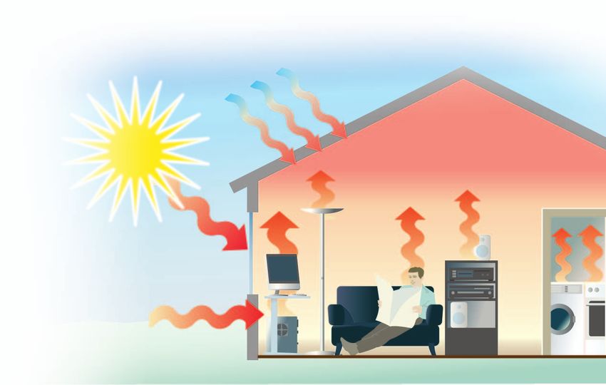
Factors influencing the latent                                                                  The effect of shading
cooling load
                                                                                               To reduce the cooling load from solar gains, the most
Moisture is introduced into a room through:                                                    efficient and sustainable way is to use passive measures.
                                                                                               From an architectural point of view, shading can be
•                    People
                                                                                               created by building components and by using blinds.
•                    Equipment and appliances                                                  Depending on the type of blinds used, the solar gain
                                                                                               can typically be reduced with up to 85% with external
•                    Air infiltration through cracks in the building, doors,
                                                                                               shading. The figures below show a building simulation
                     and windows
                                                                                               example conducted on a low-energy single family
                                                                                               house, where using different shading factors have been
                      Transmission (Sensible)                                                  applied.
External heat gain

                      Solar Radiation (Sensible)

                                       (Sensible)                       Total
                      Air                                               sensible
                                                    CONDITIONED

                      Ventilation      (Latent)
                                                       S PA C E

                                                                                    Cooling
                      Lighting         (Sensible)                                   Load
                                                                        Total
Internal heat gain

                                       (Sensible)                       latent
                      Equipment
                                       (Latent)

                                       (Sensible)
                      People
                                       (Latent)

Internal gains in residential buildings are limited to the                                     Without shading; cooling loads up to 60 W/m2.
people normally occupying the space and household
equipment. In national building regulations, the load
for internal gains in ordinary residential buildings is
often mentioned (3-5 W/m2). In residential buildings,
the cooling load primarily comes from external heat
gains, and mostly from solar gains through windows
and doors, transmission through wall and roof, and
infiltration through the building envelope/ventilation.
The figure below shows that about 2/3 of the cooling
load comes from the solar radiation.

                                                                                               Shading factor 50%; cooling loads up to 40 W/m2.
                                                    2%
                                                             5%
                                                                      3%

                                                                            10%

                        52%                                                        13%

                                                                     15%
                                                                                               Shading factor 85%; cooling loads up to 25 W/m2.

                                                                                               As can be seen from the figures above, even with the
                                                                                               most efficient shading factor, the cooling load still
                            Heat from air flows                    Heat from lighting           amounts to 25 W/m2.

                            Heat from occupants                   Heat from daylight
                            (incl. latent)                        (direct solar)
                            Heat from equipment                   Heat from windows
                                                                  (including absorbed solar)
                            Heat from walls and                   and openings
                            floors (structure)

UPONOR · FREE COOLING GUIDE                                                                                                                               7
Room variation
There is a big variation in the cooling load from room
to room, caused by the architectural design of the
building. Large window areas facing the south and west
are needed for daylight requirements and winter heat
gains, but they also incudes high summer cooling loads.
As a result of large south facing window areas, the
cooling demand in south facing rooms are higher than
in the north facing rooms. In addition, the desired
temperature levels of each room may differ ranging
from the highest temperature requirements in the
bathroom, to the lowest temperature requirements in
the bedroom.
Duration of the cooling load 37
36 No window opening, no HRV by-pass
35 Open windows, no HRV by-pass
34
33 Open windows, with HRV by-pass
The figures below show the duration of over-tempera- Temperature [°C]
32
31 UFH, no opening window
ture with different shading and ventilation strategies. 30
29
The data originates from a full year building simulation 28
27
of a low-energy single family house in Northern 26
25
European climatic conditions (Denmark). 24
23
22
21
20
19
500
1000
1500
2000
2500
3000
3500
4000
4500
5000
5500
6000
6500
7000
7500
8000
8500
Time [h]
Without shading; over-temperature up to 2 300 hours per year.
37 37
36 No window opening, no HRV by-pass 36 No window opening, no HRV by-pass
35 Open windows, no HRV by-pass 35 Open windows, no HRV by-pass
34 34
33 Open windows, with HRV by-pass 33 Open windows, with HRV by-pass
Temperature [°C]
Temperature [°C]
32 UFH, no opening window 32
31 31 UFH, no opening window
30 30
29 29
28 28
27 27
26 26
25 25
24 24
23 23
22 22
21 21
20 20
19 19
500
1000
1500
2000
2500
3000
3500
4000
4500
5000
5500
6000
6500
7000
7500
8000
8500
500
1000
1500
2000
2500
3000
3500
4000
4500
5000
5500
6000
6500
7000
7500
8000
8500
Time [h] Time [h]
Shading factor 50%; over-temperature up to 1 100 hours per year. Shading factor 85%; over-temperature up to 800 hours per year.
The simulations show that without active cooling building regulations across Europe have already started
there will be a significant amount of time with over- to implement maximum duration periods of over-
temperature (assuming that the maximum temperature temperature. In Denmark, the requirement in the 2015
allowed is 26 °C). All the cases also show that standard is that a temperature above 26 °C is only
with radiant floor cooling, it is possible to keep the allowed for maximum 100 h during the year and above
temperature below 26 °C all year round. National 27 °C for maximum 25 h during the year.
8 UPONOR · FREE COOLING GUIDE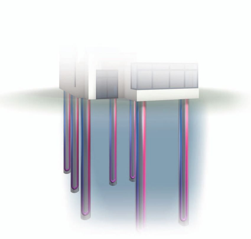
Required cooling capacity
Based on the peak load calculations of the building, the As can be seen, the cooling capacity peaks are actually
heating and cooling system can be designed. The HVAC higher (up to 4 kW), than the heating capacity peaks
system should be designed to cover the worst case (up to 3.5 kW) under any shading conditions (excluding
(peak load). The figures below show an example of the domestic hot water). Although, the heating period
variation of the needed capacity to cover the heating still remain longer than the total cooling period, it is
and cooling loads. interesting to note that the cooling period extends into
early spring and late autumn.
Required heating and cooling capacity
5000 5000
Cooling Cooling
4500 4500
Heating Heating
4000 4000
3500
Capacity [W]
3500
Capacity [W]
3000 3000
2500 2500
2000 2000
1500 1500
1000 1000
500 500
0 0
January
February
March
April
May
June
July
August
September
October
November
December
January
February
March
April
May
June
July
August
September
October
November
December
Low energy building, no shading. Low energy building, shading in-between windows.
Window opening and HRV by-pass are used during cooling season Window opening and HRV by-pass are used during cooling season
5000
4500 Cooling
Heating
4000
3500
Capacity [W]
3000
2500
2000
1500
1000
500
0
January
February
March
April
May
June
July
August
September
October
November
December
Low energy building, external shading.
Window opening and HRV by-pass are used during cooling season
UPONOR · FREE COOLING GUIDE 9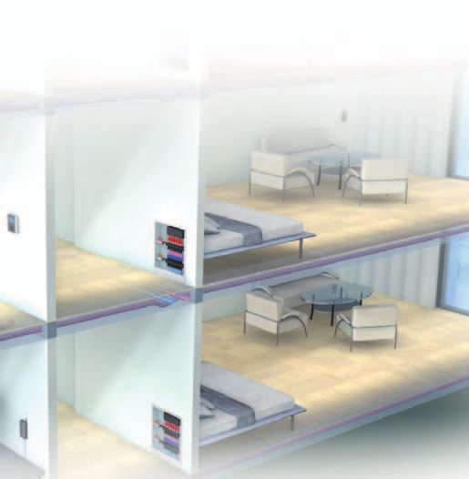
3. The ISO 7730 guidelines

     In order to provide thermal comfort, it is necessary
     to take into account local thermal discomfort caused
     by temperature deviations, draught, vertical air
     temperature difference, radiant temperature asymmetry,
     and floor surface temperatures. These factors can
     influence on the required capacity of the HVAC system.

     Optimal temperature conditions
     EN ISO 7730 is an international standard that can be
     used as a guideline to meet an acceptable indoor and
     thermal environment. These are typically measured in
     terms of predicted percentage of dissatisfied (PPD)
     and predicted mean vote (PMV). PMV/PPD basically
                                                                          The PPD predics the number of thermally dissatisfied
     predicts the percentage of a large group of people
                                                                          persons among a large group of people. The rest of
     that are likely to feel “too warm” or “too cold” (the
                                                                          the group will feel thermally neutral, slightly warm or
     EN ISO 7730 is not replacing national standards and
                                                                          slightly cool.
     requirements, which always must be followed).
                                                                          The table below shows the desired operative tempera-
     PMV and PPD                                                          ture range during summer and winter, taking into con-
                                                                          sideration normal clothing and activity level in order to
     The PMV is an index that predicts the mean value of
                                                                          achieve different comfort classes.
     the votes of a large group pf persons on a seven-point
     thermal sensation scale (see table below), based on the                                        Comfort requirements                   Temperature range
     heat balance of the human body. Thermal balance is
                                                                                                                                          Winter          Summer
     obtained when the internal heat production in the body                                                                               1.0 clo          0.5 clo
     is equal to the loss of heat to the environment.                               PPD                              PMV                  1.2 met         1.2 met
                                                                              Class [%]                               [/]                   [°C]            [°C]
                                             PPD

                                                                                         A          < 6 - 0.2 < PMV < + 0.2                21-23         23.5-25.5

                                                                                         B          < 10 - 0.5 < PMV < + 0.5               20-24         23.0-26.0
     Dissatisfied [%]

                                                                                         C          < 15 - 0.7 < PMV < + 0.7               19-25         22.0-27.0

                                                                          ISO 7730 basically recommends a target temperature
                                                                          of 22 °C in the winter, and 24.5 °C in the summer. The
                                                                          higher the deviation around these target temperatures,
                                                                          the higher the percentage of dissatisfied. The reason
                                                                    PMV   for the different target temperatures is because that the
                                                                          two seasons apply different clothing conditions as can
                                                                          be seen in below figure:
                       PMV   Predicted mean vote
                       PPD   Predicted percentage dissatisfied [%]
                                                                                                                                     Metabolic rate:
                                                                          Predicted Percentage of

                       +3    Hot                                                                                                          1.2
                                                                              Dissatisfied [%]

                       +2    Warm
                       +1    Slightly warm
                                                                                                       Basic clothing                                  Basic clothing
                        0    Neutral                                                                   insulation: 1.0                                 insulation: 0.5

                       -1    Slightly cold
                       -2    Cool
                                                                                                                         Operative temperature [°C]
                       -3    Cold
     Seven-point thermal sensation scale                                  Operative temperature for winter and summer clothing

10                                                                                                                         UPONOR · FREE COOLING GUIDE
Radiant asymmetry
When designing a radiant ceiling or wall system, make
sure to stay within the limits of radiant asymmetry. As
can be seen in the figure below, the radiant asymmetry
differs depending on the location of the emitter system,
and whether it’s used for heating or cooling.
With the insulation levels typically used today, radiant
asymmetry does normally not cause any problems
due to the moderate heating and cooling load the
Draught rate emitter has to perform. However, especially when using
ceiling heating, a calculation must be made for a given
Radiant systems are low convective systems and will reference room.
not create any problems with draught. However, down
draught from a cold wall can put a limitation to the
system. A cold wall can create draught as we know from
windows. When designing wall cooling, the velocity on
the air need to be within the recommendation (Class A
is 0.18 m/s).
Dissatisfied
0.4
Maximum air velocity, 0.5 m from wall [m/s]
Recommended comfort limit for
0.35 sedentary persons
0.3
0.25
0.2
0.15 Floor temperature
Δt (wall-room)
0.2
3.0 K 7.0 K Local discomfort caused by warm and cool floors
4.0 K 8.0 K
0.05 5.0 K 9.0 K
6.0 K 10.0 K When designing radiant cooling systems, the dew point
0
0.5 1 1.5 2 2.5 3 3.5 4 4.5
is normally reached before radiant asymmetry problems
Height of cool wall [m] occur. Can be calculated according to ISO 7726.
UPONOR · FREE COOLING GUIDE 11Surface temperatures 0,1 - 1,1 m
3
Vertical air temperature difference [K]
For many years, people have chosen underfloor heating
2,5
systems as the preferred emitter system, because of the B
perceived comfort of walking on a warm floor. Similarly, 2
the question is if the occupants complaint about discom-
1,5
fort when utilising the floor to remove heat (cooling). A
1
0 9 18 27 36 45 54 63 [°F] 0,5
80
60 0
40 Warm ceiling Cool wall 2 4 6 8 10
Dissatisfied [%]
20 ΔT floor surface room
Cool ceiling Warm wall
10
Correlation between the temperature difference floor surface to room
8 and the vertical air temperature difference (Deli, 1995).
6
4
The study concludes that up to a ΔT 8K, the comfort
2
category is still A. This would equal a floor temperature
1
0 5 10 15 20 25 30 35
of 20 °C and a dimensioned room temperature of
[°C]
Radiant temperature asymmetry [°C] 28 °C. The dimensioned room temperature must be
below 26 °C and similarly above a floor temperature
of 20 °C in order to reach comfort class B. Hence, the
According to ISO 7730, the lowest PPD (6%) is found
vertical air temperature difference will in practice not
at a floor temperature of 24 °C. A typical floor cooling
cause a indoor climate below category A.
system will have to operate with a minimum floor
temperature of 20 °C, where the expected PPD would As the pictures below show, different emitter systems
still be under 10%. As will be seen later, such floor provide different temperature gradients in a room.
temperatures still provide a significant cooling effect, Clearly, a radiant heating system in the floor provides
due to the large surface area being emitted. a temperature gradient closest to the ideal. Similarly,
a radiant cooling system in the ceiling provides a
Vertical air temperature temperature gradient closest to the ideal.
difference
The comfort categories are divided into A, B and C
depending upon the difference between the air
temperature at floor level and at a height equivalent to
a seated person. As can be seen below, the temperature
difference must be under 2°C in order to reach
category A.
18 20 22 24 26
Vertical air temperature difference a [°C]
Category °C Ideal heating Underfloor heating
Radiant ceiling heating External wall radiator heating
A4. Capacity and limitations of radiant emitter
systems
All emitter systems, whether it is pure air-based, Thermal transfer coefficient
radiators or pure radiant systems, are bounded by their
ability to transfer energy. The capacity of any radiant The thermal transfer coefficient is an expression of how
emitter systems is limited by the heat flux density, which large an effect per m2 the surface is able to transfer to
differs depending on the location of the emitter, i.e. the room, per degree of the temperature difference
floor, wall or ceiling. The heat flux density can be used between the surface and the room. The figure below
to calculate the capacity of the emitter, also known as shows the thermal transfer coefficient for different
the thermal transfer coefficient. Specifically regarding surfaces for heating and cooling respectively.
cooling, any radiant emitter will need to work within the
dew point limitations in order to avoid moisture on the [W/m2K] Surface heating and cooling
surface and within the construction. 15
Thermal transfer coefficient
Heating
Heat flux density 10
Cooling
The ability of a surface to transfer heating or cooling
between the surface and the room, is expressed by the 5
heat flux density. According to EN 1264/EN 15377,
the values below can be used to express the heat flux
0
density. Ceiling
Floor Wall
Due to natural convection, the floor provides the
Floor heating, ceiling cooling: q = 8.92 (θs,m - θi)1.1 best thermal transfer coefficient for heating while the
Wall heating, wall cooling: q = 8 (| θs,m - θi |) ceiling provides the best thermal transfer coefficient for
Ceiling heating: q = 6 (| θs,m - θi |) cooling.
Floor cooling: q = 7 (| θs,m - θi |)
Dew point limitations
Where In order to secure that there is no condensation on the
q is the heat flux density in W/m 2 surface of the emitter in the room the supply water
temperature should be controlled so that the surface
θs,m is the average surface temperature (always limited
temperatures of the emitter always is above dew point.
by dew point)
In the diagram below, the dew point temperatures can
θi is the room design temperature (operative) be found under different levels of relative humidity
(RH):
24
23
Room temp. 26 °C
22
Dew point temperature [°C]
21 Room temp. 25 °C
20 Room temp. 24 °C
19 Room temp. 23 °C
18
17
16
15
14
13
12
11
10
9
8
40 45 50 55 60 65 70 75 80
Relative humidity RH [%]
UPONOR · FREE COOLING GUIDE 13Emitter surface and humidity Theoretical capacities of
Design temperatures for cooling systems are specified embedded radiant cooling
according to the dew point. The dew point is defined by
the absolute humidity in the room and can be estimated Taking both ISO 7730 (surface temperatures, radiant
from the relative humidity RH and the air temperature. asymmetry, and down draught) and the dew point
The cooling capacity of the system is defined by the limitations into account, the following surface
difference between the room temperature and the mean temperature limitations exist.
water temperature.
45
Often standard design parameters for cooling systems 40 Heating
are an indoor temperature of 26 °C and a relative
Temperature [°C]
35 Cooling
humidity of 50%. At the dew point, condensation
will occur on the emitter surface. In order to avoid 30
condensation, the emitter surface temperature has to be 25
above the dew point temperature. 20
For radiant floor cooling a minimum surface temperature 15
Floor Parimeter Ceiling Wall
of 20 °C is required, which means that only when the
relative humidity exceeds 70% in the room, the risk Surface temperature limitations
of condensation occurs, because that corresponds to
a relative humidity of 100% at the emitter surface. With these surface temperature limitations in mind, the
Radiant cooling from the ceiling is limited by the radiant maximum capacities of different radiant emitter systems
asymmetry between the surface of the emitter and the can be calculated. The results are shown in the figure
room temperature recommendation is that it should not below.
exceed more than 14 K. For standard conditions (26 ºC,
50% RH) the surface of the emitter usually reaches the 200
dew point before the radiant asymmetry limit. 180 Heating
Heating and Cooling Capacity [W/m2]
Cooling
160
Distribution pipes and manifolds
140
In any cooling system where you have distribution pipes
120
or manifolds you have to be aware of that these parts
100
of the system also have a risk of condensation because
they sometime operates below the dew point. Insulation 80
of distribution system is often necessary in order to 60
avoid condensation. 40
20
Design temperature
0
Floor Parimeter Ceiling Wall
The design supply water temperature of the system
depends on the type of surface used, the design indoor Maximum heating a cooling capacities
conditions (temperature and relative humidity) and the
cooling loads to be removed. It should be calculated to In theory, the highest heating capacity can be achieved
obtain the maximum cooling effect possible from the from the wall. Since space is limited due to windows
system. and other things hanging on the wall, the real heating
capacity from walls is significantly reduced. Hence, the
The capacity and mean water temperature for radiant
biggest capacity can be achieved by heating from the
floor cooling depends on the floor construction, pipe
floor, and cooling from the ceiling. In practice, either
pitch and surface material. To have the highest possible
a floor system or a ceiling system is installed and used
capacity of the system you should design your floor
for both heating and cooling. A floor system should
construction so the surface temperature is equal to the
be chosen if the heating demand is dominant and a
minimum temperature of 20 °C.
ceiling system should be chosen if the cooling demand
The capacity and mean water temperature for radiant is dominant.
cooling from the ceiling is calculated, or can be read
directly, in the capacity diagram of the cooling panels.
To have the highest possible capacity of the system you
should design as close to the dew point as possible.
14 UPONOR · FREE COOLING GUIDE5. Ground heat exchangers
Ground conditions
When planning the use of ground heat exchangers, on being in contact with ground water. Hence the depth
the ground conditions are of fundamental importance. of ground water levels has an important impact on the
Determining the ground properties, with respect to performance of a vertical ground heat exchanger.
the water content, the soil characteristics (i.e. thermal
In addition to the water concentration, different ground
conductivity), density, specific and latent thermal
types have different thermal conductivity. For example
capacity as well as evaluating the different heat and
rock has a higher thermal conductivity than soil, so
substance transport processes, are basic pre-requisites
ground conditions with granite or limestone will give a
to determine and define the capacity of a ground heat
better performing ground heat exchanger than sand or
exchanger. The dimensioning has a significant impact
clay.
on the energy efficiency of the heat pump system.
Heat pumps with a high capacity have unnecessary
Thermal conductivity
high power consumption when combined with a poorly
Soil type (W/m K)
dimensioned heat source.
Clay/silt, dry 0.5
With a higher water concentration in the ground, you Clay/silt, waterlogged 1.8
get a better system capacity. Horisontal collectors are
Sand, dry 0.4
hence depending on the ground’s ability to prevent rain
water from mitigating downwards due to gravitation. Sand, moist 1.4
The smaller the corn size in the soil, the better the Sand, waterlogged 2.4
ground can prevent rain water from gravitation. Hence Limestone 2.7
clay will provide a better performing ground heat Granite 3.2
exchanger than sand. Vertical collectors are depending
Source: VDI 4640
UPONOR · FREE COOLING GUIDE 15Ground heat exchangers
With ground heat exchangers, a distinction is made The suitability of the different collectors depends on the
between horisontal and vertical collectors. These can be environment (soil properties and climatic conditions),
further classified as follows: the performance data, the operating mode, building
type (commercial or private), the space available and
Horisontal:
the legal regulations.
• Horisontal or surface collectors
• Energy cages
Vertical:
• Boreholes
• Energy piles and walls
Horisontal collectors Energy cages
Collectors installed horisontally or diagonally in the Collectors installed vertically in the ground. Here, the
upper five meters of the ground (surface collector). collector is arranged in a spiral or a screw shape. Energy
These are individual pipe circuits or parallel pipe cages are a special form of horisontal collectors.
registers which are usually installed next to the building
and in more rare cases under the building foundation.
Boreholes Energy piles
Collectors installed vertically or diagonally in the Collectors build into the pile foundations that are
ground. Here one (single U-probe) or two (double used in construction projects with insufficient load
U-probe) pipe runs are inserted in a borehole in capacity in the ground. Individual or several pipe runs
U-shape or concentrically as inner and outer tubes. are installed in foundation piles in a U-shape, spiral or
meander shape. This can be done with pre-fabricated
foundation piles or directly on the construction site,
where the pipe runs are placed in prepared boreholes
that are then filled with concrete. Most often energy
piles are used for larger commercial buildings.
16 UPONOR · FREE COOLING GUIDEGround temperature profile Dimensioning of ground heat
The figure below shows a generic temperature profile in
exchangers for free cooling
the ground for each season during the year.
The first thing to decide is whether the ground heat
exchanger shall be used for heating only or for both
Temperature (earth’s surface) [°C]
0 5 10 15 20
heating and cooling. As demonstrated in this guide,
0
new built low energy houses will often have substantial
cooling loads. It is therefore highly recommendable to
use the ground heat exchanger for free cooling in the
5 summer period. A combined use for heating and cooling
also balances of the ground temperature during the
Depth in soil [m]
year and leaves the ground environment undisturbed.
10
Existing guidelines for dimensioning ground heat
exchangers are typically based on the peak load for the
heating demand. But in order to ensure that adequate
15 1. February cooling capacity is available in the summer season, it
1. May
is recommend doing a design check for the maximum
1. November
1. August cooling load as well.
20 Dimensioning for the heat load should be done based
0 5 10 15 20
on the peak load for space heating plus the domestic
Temperature (depth) [°C]
hot water need. As a heat pump is used for covering
the heat load, the COP of the heat pump on the
The closer to the ground surface, the higher the coldest day (design day) should be applied in the
influence from the outside temperature and solar design calculation. In addition to this, the specific
radiation. Hence not surprisingly, the highest characteristic of the chosen heat exchanger and the
temperatures are found in late summer and the thermal conditions in the ground must be taken into
lowest temperatures in late winter. The reason for the account.
temperatures being higher in late autumn than late Dimensioning for the cooling load should be done
spring, has to do with the ground’s ability to store based on valid information of the maximum cooling
energy. After a warm summer period, the ground load in the building. Free cooling operates without a
remains relatively warm during the autumn. Ground heat pump. It is therefore vital that the thermal capacity
temperatures stabilize below 10-15 m. It is clear from of the ground heat exchanger is able to fully cover the
these ground temperature profiles that the cooling max cooling load (no COP is included). In residential
capacity is higher below 15 m. Hence vertical collector buildings in Northern Europe the cooling need will
systems provides a better cooling capacity than normally be covered with the capacity derived from
horisontal collector systems. the heating requirements. But a design check is always
recommended.
Primary supply temperatures In special cases in residential buildings and typically in
office buildings, the cooling need will be dominant and
The temperatures mentioned in the previous section
thus the design driver. In such case vertical collectors
are often referred to as the undisturbed ground
are normally recommended as the deeper ground
temperature. Depending on the thermal resistance
temperatures are sufficiently stable and independent of
between the collector and the surrounding ground, the
surface temperature and solar radiation. If a horizontal
temperature of the fluid in the collector will be higher
system is chosen, the space requirements can be a
than the surrounding ground.
capacity limitation. Designing for inadequate cooling
capacity on the warmest summer days may then
be necessary compromise, but should be evaluated
carefully.
UPONOR · FREE COOLING GUIDE 17Dimensioning examples
In order to dimension ground heat exchangers cer- data (thermal conductivity etc.) from local databases
tain information has to be considered. First of all an or authorities. The figures below show the capacity for
estimation of the physical properties of the ground is different collectors.
needed. Normally its possible to obtain local ground
*) Energy cage; normal height is 2.0 m, and Horisontal collectors Energy cage Vertical collectors
XL height 2.6. Required depth is 4 m.
Pipe size 25, 32 and 40 mm Normal 32 mm XL 32 mm 40 mm
Capacity cooling 7-28 W/m2 800-1120 W 1000-1500 W 30-70 W/m
Dimensioning temperature,
17-20 °C 14-17 °C 10-13 °C 10-13 °C
supply/return
Flow and pressure drop in the collector
When the cooling need is defined, the flow can be different from the physical properties of pure water.
calculated. When using ground collectors, the water The table below shows the required flow of often used
used has to be mixed with anti-frost liquid. Hence, brines for providing different cooling capacity.
the specific heat capacity and density in the brine is
Cooling need Ethanol Monoethylenglyciol Propylenglycol
[kW] Flow [kg/s] Flow [l/s] Flow [kg/s] Flow [l/s] Flow [kg/s] Flow [l/s]
2 0.16 0.15 0.18 0.19 0.17 0.18
3 0.24 0.23 0.27 0.28 0.26 0.27
4 0.32 0.31 0.36 0.38 0.34 0.36
5 0.40 0.38 0.45 0.47 0.43 0.45
6 0.48 0.46 0.54 0.56 0.51 0.54
When calculation the pressure loss in the collector the In the diagram below, the pressure loss in the
flow is divided equally up in the number of loops. For ground collector should be maximum 34 kPa at the
vertical collectors the total pressure loss is normally dimensioning conditions, and the ground collector
very low hence the pressure is equalized and it is only should be dimensioned so that the pressure loss in each
the pressure loss in the feeding pipe has an influence. loop is less than 34 kPa.
For horisontal collectors and partly energy cages
Pump diagram
the pressure loss has to be calculated in order to be
Available pressure for the primary circuit.
sure that the pump will be able to circulate the water
through the collector and the cooling exchanger
Pressure loss [kPa]
including manifolds and valves.
50
Example: 4 kW installations
40
Horisontal collector extraction 15 W/m2 30
CP2
power CP1
20
Liquid Monoethylenglycol
10
Total flow 0.38 l/s, 1.37 m3/h
0
0 0.5 1 1.5 2 2.5 3
Diameter of collector Ø 32 mm
Rate of flow [m3/h]
18 UPONOR · FREE COOLING GUIDE6. Free cooling in combination with different heat
sources
The illustrations below shows a ground heat exchanger As one can see from the grey connection lines the pump
combined with a radiant system in heating mode and and exchanger group is not active in heating mode.
cooling mode. In this example a ground sourced heat Similarly, the connection lines from the heat pump (or
pump is providing heating to domestic hot water any other heat source) to the emitter systems are in-
(DHW), space heating, and for heating up the incoming active in cooling mode.
ventilation air. This could of course be utilized with If a boiler or district heating system is used as heating
other heat sources such as boilers or district heating. source, the ground heat exchanger will only work during
Free cooling is provided through a special pump and cooling (also known as a bivalent system). If a ground
exchanger group (see chapter 8) that supplies cold source heat pump is used as heat source, the ground
water/brine from the ground heat exchanger directly to ground heat exchanger will work both during heating
the radiant emitter system and possibly the incoming and during cooling (also known as a monovalent
ventilation air. In cooling mode, the heat pump will only system).
be active for domestic hot water generation.
Heating mode, the free cooling is deactivated Cooling mode, the free cooling is activated
UPONOR · FREE COOLING GUIDE 197. Choosing and dimensioning the radiant emitter
system
Embedded emitters are the key to any radiant system. the floor has the highest heating efficiency, but with a
In order to have an energy efficient and comfortable lower cooling efficiency.
solution, the emitter system has to be designed to
Another important factor is the supply water
the construction but also to the task it has to solve.
temperature. Radiant emitter systems operate on a
There are many types of constructions for floor, wall
relatively low temperature for heating, and a relatively
and ceilings. Uponor offers emitters that can meet the
high temperature for cooling. A radiant system should
requirements of all types of installations. All emitters
be designed for the lowest possible temperature for
are able to provide heating and cooling. However, some
heating and the highest possible temperature for
emitters are more efficiently than others. The most
cooling. This secures a heating/cooling system with
efficient cooling system is placed in the ceiling, but the
high energy efficiency and optimal conditions for the
heating efficiency is lower whereas an emitter system in
heating and cooling supply.
Floor installation Wall installation Ceiling installation
Capacity of different radiant
emitter systems
In order to calculate the capacity of the radiant emitter,
it is important to know the construction in which the
embedded emitter is integrated, including the surface
material on top of the construction. In general, there are
three factors that influence on the capacity of a radiant
emitter system:
• Thermal resistance in the surface construction RB
• Pipe pitch, i.e. the distance between the pipes T
• Thermal conductivity in the construction material
In practice, this means that when designing the floor
construction, the performance of the radiant system can
be optimised by choosing the right construction, pipe
Example: floor construction
layout and surface material.
20 UPONOR · FREE COOLING GUIDEY = Specific thermal output qc [W/m2]
Thermal resistance in the surface X = Temperature difference between
construction room and cooling medium [θc K]
The thermal resistance in the surface construction has a
RλB = 0
big influence on the performance of the emitter. In the
qCN (RλB = 0)
diagram, an example of a cooling curve where different RλB = 0.05
thermal resistance values from 0.00 to 0.15 m2K/W are RλB = 0.10
shown. The curve shows that higher resistance gives a
lower capacity. All constructions with embedded radiant
qCN (RλB = 0.15) RλB = 0.15
emitter systems will have a surface resistance that has to
be considered. In order to get the highest efficiency, the
resistance value has to be as low as possible.
ΔθCN
Field of characteristic curves of a cooling system
Pipe pitch, i.e. distance between the 45
pipes
40
The pipe pitch, i.e. the distance between the pipes in
the embedded construction, not only has an influence 35
Thermal output q [W/m2]
on the capacity, but also on how equal the surface
30
temperature is. This is especially important from a
comfort perspective. 25
The diagram shows the capacity of a concrete floor
20
construction with =1.8 W/(mK), and with different
kinds of surface material. The diagram illustrates the 15
variation of the capacity depending on the pipe pitch.
A short distance between the pipes, gives a higher 10
0.1 0.15 0.2 0.25 0.3 0.35 0.4 0.45 0.5
capacity and vice versa. For a combined heating and Pipe spacing T [m]
cooling system, it is recommended to use a relatively
small distance 300 mm between the pipes, in order θm 15.5 °C, θm 18.5 °C,
14 mm parquet 14 mm parquet
to utilise free cooling and maintain an even surface
temperature. θm 15.5 °C, θm 18.5 °C,
7 mm parquet 7 mm parquet
θm 15.5 °C, θm 18.5 °C,
10 mm tiles 10 mm tiles
Floor surface temperature limit 20 °C
Thermal conductivity in the construction
The thermal conductivity in the construction has an For dry constructions, high performance material like
effect on the system’s ability to distribute heating and heat distribution plates in aluminium or similar are used
cooling in the thermal mass. A construction with a low to ensure optimal heating and cooling distribution.
thermal conductivity requires a smaller pipe pitch, in
order to obtain an equal surface temperature variation.
UPONOR · FREE COOLING GUIDE 21Radiant floor constructions and
capacity
Radiant floor systems are far more common than using a relatively short distance between the pipes, and
ceiling or wall systems, and can be used for cooling and a surface material with a low thermal resistance.
heating. A radiant floor system can be installed in wet
In the figure below, an overview of the capacity in
constructions using concrete and screed, and in dry
the most common floor installations is shown with
constructions with heat emissions plates.
mean water temperatures of 15.5 °C and 18.5 °C
A radiant floor has a cooling capacity of up to 42 W/m2 corresponding to supply temperatures of 14 °C and
limited by a surface temperature of 20 °C. The most 17 °C with a T of 3 K over the emitter loops. Figures
efficient installation is in a wet construction with con- are based on a room temperature of 26 °C and a surface
crete or screed, because of its high heat conductivity, temperature of 20 °C.
Surface material Surface material
Tiles 10 mm, = 1.0 W/mK Wood 14 mm parquet, = 0.014 W/mK
Cooling effect Cooling effect Cooling effect Cooling effect
Floor Installation
q [W/m2] q [W/m2] q [W/m2] q [W/m2]
installation principle
θm 15.5 °C θm 18.5 °C θm 15.5 °C θm 18.5 °C
Wet floor
42 40 33 24
installation
Installation
integrated in 42 40 33 24
construction
Installation on the
28 20 27 19
joists
Dry floor
28 20 27 19
installation
Installation
24 17 18 14
between the joists
22 UPONOR · FREE COOLING GUIDERadiant wall constructions and
capacity
Radiant wall systems are typically used as a supplement by a surface temperature of 17 °C, in order to be within
to floor and ceiling emitter systems for rooms the limits of radiant asymmetry and to prevent draught.
with a higher need for cooling/heating. Instead of
In the figure below, an overview of the capacity of the
dimensioning the floor or ceiling system according to
most common wall systems is shown with mean water
the room with the highest peak load, it can be designed
temperatures of 15.5 °C and 18.5 °C corresponding
according to the average and the peak room(s) can be
to supply temperatures of 14 °C and 17 °C with a T
supplemented with a wall emitter.
of 3 K over the emitter system. Figures are based on a
A radiant wall system will be limited by the architecture room temperature of 26 °C and a surface temperature
and by the furnishing. Radiant wall systems have a of 20 °C .
cooling capacity of up to 60 W/m2 (active area) limited
Surface material Surface material Surface material
Plaster 10 mm, = 0.7 W/mK Plaster 11 mm, = 0.24 W/mK Plaster 11 mm, = 0.23 W/mK
Cooling effect Cooling effect Cooling effect Cooling effect Cooling effect Cooling effect
Wall Installation q [W/m2] q [W/m2] q [W/m2] q [W/m2] q [W/m2] q [W/m2]
installation principle θm 15.5 °C θm 18.5 °C θm 15.5 °C θm 18.5 °C θm 15.5 °C θm 18.5 °C
Dry wall
45 32
installation
Wet wall
60 45
installation
Stud wall
42 34
installation
UPONOR · FREE COOLING GUIDE 23Radiant ceiling constructions
and capacity
Radiant ceiling systems are the most efficient systems attention has to be taken for adequate dew point
for cooling, but can also be used for heating. Ceiling control.
systems have originally been developed for office
In the figure below, an overview of the capacity in
environments, but are also available for residential
the most common ceiling systems is shown, with
constructions using wet plaster or dry gypsum panels.
mean water temperatures of 15.5 °C and 18.5 °C
Radiant ceiling systems have a cooling capacity of up corresponding to supply temperatures of 14 °C and
to 97 W/m2. It is important to note that especially for 17 °C with a T of 3 K over the emitter system. Figures
ceiling cooling, the surface temperature of the system are based on a room temperature of 26 °C and a surface
is in peak often very close to the dew point. Special temperature of 16 °C.
Surface material Surface material Surface material
Plaster 10 mm, = 0.7 W/mK Plaster 11 mm, = 0.24 W/mK Plaster 11 mm, = 0.23 W/mK
Ceiling Cooling effect Cooling effect Cooling effect Cooling effect Cooling effect Cooling effect
Installation
installation q [W/m2] q [W/m2] q [W/m2] q [W/m2] q [W/m2] q [W/m2]
principle
θm 15.5 °C θm 18.5 °C θm 15.5 °C θm 18.5 °C θm 15.5 °C θm 18.5 °C
Wet ceiling
75 55
installation
Dry ceiling
59 42
installation
Suspended
ceiling 97 67
installation
Capacity diagrams
Uponor offers a wide range of embedded emitter 3. Pipe pitch, i.e. centre distance between the pipes T
systems adapted to different kinds of constructions in [cm]
the floor, wall or ceiling. Whenever the choice of system
4. Difference between room temperature and mean
has been selected, detailed diagrams can be used in
water temperature θc. = θi - θc [K]
order to make the planning of the capacity. The diagram
and example on next page shows a floor construction 5. Recommended minimum surface temperature
with the cooling and heating output of the emitter (20 °C)
system.
6. Difference between room temperature and surface
temperature θv - θr, m [K]
Dimensioning diagram for cooling
If three of the parameters above are known, the
Analogue to dimensioning for heating, the following
remaining parameters can be calculated using the
parameters must be considered:
diagram to the right.
1. Cooling effect of the radiant area qc [W/m2]
2. Thermal resistance in the surface construction RB
[m2 K/W]
24 UPONOR · FREE COOLING GUIDE100
T 15
T 20
T 25 K
= 15
Ðθ
Thermal output heating qH [W/m2]
i
=θ
80 T 30 H
80
Δθ
Thermal output cooling qc [W/ m2]
H
60 60
10 K
8K
40 40
6K
20 =4K 20
Δθ = θ Ðθ
C
i C
0 0
30 5 20 T 15 T 10
T T2 T T qH Δθ H,N
Thermal resistance RB [m2 K/W]
0,05
cm W/m2 K
0,10
Heating 10
15
20
98,6
96,3
93,0
15,9
18,1
20,3
25 87,3 22,0
30 81,3 23,6
0,15 0
20 15 T 10
25
T T
T
0,05
Δθ C,N
Cooling T
cm
10
qC
W/m2
34,8
K
8 0,10
15 39,8 8
20 27,5 8
25 24,5 8
0,15
Dimensioning example for cooling
Estimating the dimensioned supply water temperature θV, Ausl. Calculated: θr, m = i - 4.3 K
Given: qc = 29 W/m² θr, m = 21.7 °C
θi = 26 °C (O.K., as this is above the recommended
RB = 0.05 m² K/W minimum surface temperature (20 °C)
Chosen pipe pitch = Vz 15 θV, calc. = θi - θc - (θv- θR)/2
T: θv - θH = 2 K θV, calc. = 26 - 9 - 2/2
θV, calc. = 16 °C
Read from the diagram: θc = 12 K
θr, m - θi = 3.9 K
Note: The required cooling effect can only be achieved to avoid condensation, a supply water controller such as
if the median surface temperature and the dimensioned Uponor Climate Controller C-46 is needed.
supply temperature are above the dew-point. In order
UPONOR · FREE COOLING GUIDE 25Regulation and control
The purpose of a control systems is to keep one room control causes the room with the highest demand
or more climate parameters within specified limits to determine the heating or cooling supply to a full
without a manual interference. Heating and cooling zone, resulting in over temperatures and unnecessary
systems require a control system in order to regulate high energy consumption.
room temperatures during shifting internal loads and
An individual room control system is much
outdoor temperatures. Good control systems adapt
preferable in order to meet room specific load variations
to the desired comfort temperatures while minimising
and individual comfort requirements. Due to high
unnecessary energy use.
variations in the individual room loads in low-energy
In residential buildings two different types of controls buildings, an individual room control system is also
principles are common; zone control and individual required to minimise the energy consumption.
room control.
The basic principle in an individual room control system
In a zone control system, the temperature is is that a sensor measures the room temperature and
controlled in a common zone consisting of several regulates the heating or cooling supplied to the space
rooms and heating and cooling is supplied evenly to controlled in order to meet a user defined temperature
the full zone. Not all national building codes allow set point. The most well-know examples are radiators
zone control systems as they have major shortfalls with with thermostatic valves and underfloor heating systems
comfort as well as energy consumption. with room thermostats.
In low-energy buildings there will in particular be high In addition, room by room regulation provides the
variations in the individual room heating and cooling possibility to shut down cooling in a specific room, such
loads (see figure 5.2). This means that lack of individual as a bathroom or a room without cooling loads.
Room 1
Living room Kitchen
18°C
21°C 21°C
Room 2
Bedroom Bath 1 Room 3 Entrance Bath 2
18°C
21°C 22°C 21°C 20°C 22°C
Typical desired temperature (set points) in a single family house. Typical variation between individual room heat demands in a
low-energy house.
26 UPONOR · FREE COOLING GUIDEThe self-regulating effect in Functional description of
underfloor heating Uponor Control System
Radiant floor heating and cooling benefits from a
Individual room control with traditional
significant effect called ”self control” or “self regulating
on/off functionality
effect”. The self regulating effect occurs because the
heat exchange from the emitting floor is proportional For a radiant floor heating and cooling system, the
to the temperature difference between the floor and control is normally split up in a central control and
the room. This means that when room temperature individual room controls. The central control unit is
drifts away from the set point, the heat exchange will placed at the heat source. It controls the supply water
automatically increase. temperature according to the outside temperature
based on an adjustable heat curve. The individual room
The self regulating effect depends partly on the
control units (room thermostats) are placed in each
temperature difference between room and floor surface
room and controls the water flow in the individual
and partly on the difference between room and the
underfloor heating circuit by ON/OFF control with a
average temperature in the layer, where the pipes are
variable duty cycle. Its done according to the set-point
embedded. It means that a fast change of the operative
by opening and closing an actuator placed at the central
temperature will equally change the heat exchange.
manifold.
Due to the high impact the fast varying heat gains
(sunshine through windows) may have on the room Individual room control with DEM
temperature, it is necessary that the heating system can technology
compensate for that, i.e. reduce or increase the heat
Uponor’s Dynamic Energy Management control
output.
principle is an advanced individual room system based
Low-energy houses will largely benefit from the self on innovative technology and an advanced self learning
regulating effect, because the temperature difference algorithm. Instead of a simple ON/OFF control, the
between floor and room will be very small. A typical actuators on the manifold supplies the energy to each
low-energy house has on average for the heating room in short pulses determined based on feedback
season a heat load of 10 to 20 W/m² and for this size of from the individual room thermostats.
heat load, the self regulating effect will be in the range
Uponor Control System DEM is self learning and will
of 30 - 90%.
remember the thermal behavior of each room. This
°C ensures an adequate and very accurate supply of
27 energy, which means better temperature control and
= Floor surface temperature energy savings.
26
= Room temperature
c cooling = -10.5 W/m2 Saved energy when
25
Higher using Uponor DEM technology Actuator on/off
temperature
+
c
24
23 Thermostat set
point 20 °C
22
b Uponor DEM
Lost energy when
technology
21 using Uponor DEM technology
a Lower
b heating = 13.9 W/m2 temperature -
Time
20
a heating = 19.1 W/m2
19 Typical behaviour in a heavy floor construction, where Uponor
Time
DEM technology ensures that a minimum of energy is lost to the
construction. Compared with traditional on/off regulation, saving
Self-regulating effect. UFH/C outputs for different temperatures figures between 3-8% can be obtained.
between room and floor surface.
UPONOR · FREE COOLING GUIDE 27You can also read