Evaluation of Type IV Fluids Applied Using Forced Air Assist Equipment
←
→
Page content transcription
If your browser does not render page correctly, please read the page content below
TP 14445E

Evaluation of Type IV Fluids Applied
 Using Forced Air Assist Equipment

                   Prepared for
        Transportation Development Centre

                In cooperation with
                  Civil Aviation
                Transport Canada
                       and
        The Federal Aviation Administration
        William J. Hughes Technical Center

                   Prepared by

                                               November 2005
                                              Final Version 1.0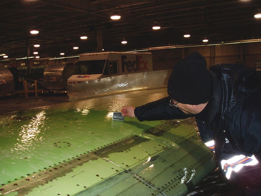
TP 14445E

Evaluation of Type IV Fluids Applied
 Using Forced Air Assist Equipment

                    By:
            Stephanie Bendickson

                                    November 2005
                                   Final Version 1.0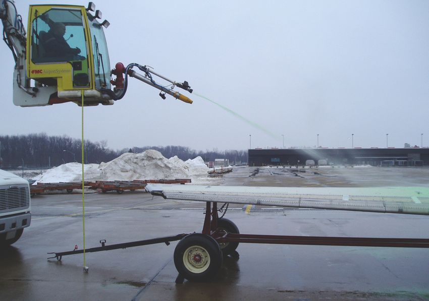
The contents of this report reflect the views of APS Aviation Inc. and
      not necessarily the official view or opinions of the Transportation
      Development Centre of Transport Canada.

      The Transportation Development Centre does not endorse products or
      manufacturers. Trade or manufacturers’ names appear in this report
      only because they are essential to its objectives.

                        DOCUMENT ORIGIN AND APPROVAL RECORD

      Prepared by:

                              ___________________________________________________
                              Stephanie Bendickson, B.Comm.                 Date
                              Project Analyst

      Reviewed by:

                              ___________________________________________________
                              John D’Avirro, B.Eng.                         Date
                              Program Manager

      Approved by: **
                   ___________________________________________________
                   Jean Valiquette                               Date
                   President, APS Aviation Inc.

Un sommaire français se trouve avant la table des matières.

              This report was first provided to Transport Canada as Final Draft 1.0 in November 2005.
                              It has been published as Final Version 1.0 in May 2020.

     **Final Draft 1.0 of this report was signed and provided to Transport Canada in November 2005. A Transport
     Canada technical and editorial review was subsequently completed and the report was finalized in May 2020;
     Jean Valiquette was not available to participate in the final review or to sign the current version of the report.

                                       M:\Projects\PM1892 (TC Deicing 04-05)\Reports\Forced Air\Final Version 1.0\TP 14445E Final Version 1.0.docx
                                                                                                                         Final Version 1.0, May 20
                                                                 ii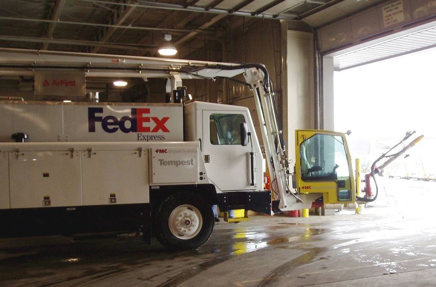
PREFACE

PREFACE

Under contract to the Transportation Development Centre of Transport Canada, APS
Aviation Inc. has undertaken a research program to advance aircraft ground de/anti-icing
technology. The specific objectives of the APS Aviation Inc. test program are the
following:

•   To develop holdover time data for all newly-qualified de/anti-icing fluids;
•   To conduct endurance time tests in frost on various test surfaces;
•   To assist with the operational evaluation of Type III fluids;
•   To finalize the laboratory snow test protocol with Type II, III and IV fluids;
•   To evaluate weather data from previous winters to establish a range of conditions
    suitable for the evaluation of holdover time limits;
•   To assist the SAE G-12 Ground Equipment Subcommittee in evaluating forced air-assist
    systems;
•   To evaluate the possibility of using a fluid failure sensor in holdover time testing;
•   To conduct endurance time tests on non-aluminum plates;
•   To examine the effect of heat on Type II, III and IV fluid endurance times;
•   To provide support for human factor tactile tests; and
•   To conduct general and exploratory de/anti-icing research.

The research activities of the program conducted on behalf of Transport Canada during the
winter of 2004-05 are documented in nine reports. The titles of the reports are as follows:

• TP 14443E        Aircraft Ground De/Anti-Icing Fluid Holdover Time Development Program
                   for the 2004-05 Winter;
• TP 14444E        Winter Weather Impact on Holdover Time Table Format (1995-2005);
• TP 14445E        Evaluation of Type IV Fluids Applied Using Forced Air Assist Equipment;
• TP 14446E        A Sensor for Detecting Anti-Icing Fluid Failure: Phase II;
• TP 14447E        Effect of Heat on Endurance Times of Anti-Icing Fluids;
• TP 14448E        Aircraft Ground Deicing Fluid Endurance Times on Composite Surfaces;
• TP 14449E        Development of Ice Samples for Visual and Tactile Ice Detection
                   Capability Tests;
• TP 14450E        Development of Ice Samples for Comparison Study of Human and
                   Sensor Capability to Detect Ice on Aircraft; and
• TP 14451E        Aircraft Ground Icing General Research Activities During the 2004-05
                   Winter.

                               M:\Projects\PM1892 (TC Deicing 04-05)\Reports\Forced Air\Final Version 1.0\TP 14445E Final Version 1.0.docx
                                                                                                                 Final Version 1.0, May 20
                                                         iii
PREFACE

In addition, the following interim report is being prepared:

• Substantiation of Aircraft Ground Deicing Holdover Times in Frost Conditions.

This report, TP 14445E, has the following objective:

•   To evaluate Type IV fluids applied using forced air assist.

To satisfy this objective, APS Aviation Inc. personnel travelled to the FedEx facility in
Pittsburgh, Pennsylvania to participate in forced air systems testing.

PROGRAM ACKNOWLEDGEMENTS

This multi-year research program has been funded by the Civil Aviation Group, Transport
Canada with support from the Federal Aviation Administration, William J. Hughes
Technical Center, Atlantic City, NJ. This program could not have been accomplished
without the participation of many organizations. APS Aviation Inc. would therefore like to
thank the Transportation Development Centre of Transport Canada, the Federal Aviation
Administration, National Research Council Canada, the Meteorological Service of Canada,
and several fluid manufacturers.

APS Aviation Inc. would also like to acknowledge the dedication of the research team,
whose performance was crucial to the acquisition of hard data. This includes the following
people: Stephanie Bendickson, Nicolas Blais, Michael Chaput, Sami Chebil, John D’Avirro,
Peter Dawson, Stéphane Gosselin, Mark Mayodon, Chris McCormack, Nicoara Moc,
Filomeno Pepe, Marco Ruggi, Joey Tiano, Kim Vepsa, and David Youssef.

Special thanks are extended to Barry Myers, Frank Eyre and Yagusha Bodnar, who on
behalf of the Transportation Development Centre, have participated, contributed and
provided guidance in the preparation of these documents.

PROJECT ACKNOWLEDGEMENTS

APS Aviation Inc. would like to thank the staff at the FedEx facility in Pittsburgh for
accommodating the mobile laboratory and assisting the lab team as required.

APS Aviation Inc. would also like to thank AéroMag 2000 for providing assistance during
shipment of the Transport Canada JetStar wing.

                               M:\Projects\PM1892 (TC Deicing 04-05)\Reports\Forced Air\Final Version 1.0\TP 14445E Final Version 1.0.docx
                                                                                                                 Final Version 1.0, May 20
                                                        iv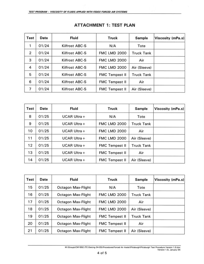
Transport         Transports                                                                                                          PUBLICATION DATA FORM
                  Canada            Canada
 1.    Transport Canada Publication No.                               2.    Project No.                                                    3.    Recipient’s Catalogue No.

       TP 14445E                                                            5498-5501 (a-d)
 4.    Title and Subtitle                                                                                                                  5.    Publication Date

       Evaluation of Type IV Fluids Applied Using Forced Air Assist Equipment                                                                    November 2005

                                                                                                                                           6.    Performing Organization Document No.

                                                                                                                                                 CM1892.001
 7.    Author(s)                                                                                                                           8.    Transport Canada File No.

       Stephanie Bendickson                                                                                                                      2450-BP-14
 9.    Performing Organization Name and Address                                                                                            10.   PWGSC File No.

       APS Aviation Inc.                                                                                                                         MTB-3-01379
       634 Saint-Jacques St., 4th Floor                                                                                                    11.   PWGSC or Transport Canada Contract No.
       Montreal, Quebec, H3C 1C7
                                                                                                                                                 T8200-033534
 12.   Sponsoring Agency Name and Address                                                                                                  13.   Type of Publication and Period Covered

       Transportation Development Centre                                                                                                         Final
       Transport Canada
       800 René-Lévesque Blvd West, Suite 600                                                                                              14.   Project Officer

       Montreal, Quebec, H3B 1X9                                                                                                                 Antoine Lacroix for Barry Myers
 15.   Supplementary Notes (Funding programs, titles of related publications, etc.)

       Several research reports for testing of de/anti-icing technologies were produced for previous winters on behalf of Transport Canada. These are
       available from the Transportation Development Centre. Nine reports (including this one) were produced as part of this winter’s research program.
       Their subject matter is outlined in the preface. This project was co-sponsored by the Federal Aviation Administration.
 16.   Abstract

       Forced air systems have been in development for more than five years. One major concern is that current holdover
       time values may not be valid when Type II or Type IV fluids are applied with forced air systems. Testing by FedEx
       in 2003-04 compared the viscosity of fluids applied with forced air to the viscosity of fluids applied with a conventional
       system. The tests showed that fluid viscosity decreased more with a forced air application than with a conventional
       application.

       Two changes were made to the Type II/IV procedure following the unsuccessful 2003-04 test session. First, the
       approval criterion was changed: the viscosity of fluid applied with the forced air system would be compared to the
       lowest on wing viscosity instead of to the conventional application viscosity. Second, a requirement was added that
       pre-tests be conducted to fix the equipment setup prior to evaluation of the equipment with specific fluids.

       Using the new test procedure, FedEx conducted tests in January 2005 with four Type IV fluids and two forced air
       deicing trucks. One of the four tested fluids could be approved for use without restrictions on viscosity. Two fluids
       could be approved for use with forced air with limitations on delivered viscosities. One fluid could not be approved
       as the sample sent for testing did not conform to the test requirements.

       Following the test session, it was concluded that the new procedure was an improvement over the previous version
       of the procedure, and that the changes should remain in the procedure for future testing.

 17.   Key Words                                                                                         18.   Distribution Statement

       Viscosity, Forced Air, Air Assist, Holdover Times,                                                      Limited number of copies available from the
       Fluids, Lowest On-Wing Viscosity                                                                        Transportation Development Centre

 19.   Security Classification (of this publication)                  20.   Security Classification (of this page)                  21.   Declassification         22.   No. of   23.     Price
                                                                                                                                          (date)                         Pages
       Unclassified                                                         Unclassified                                                        —                    xviii, 38               —
                                                                                                                                                                      apps
CDT/TDC 79-005
Rev. 96

                                                                                                    v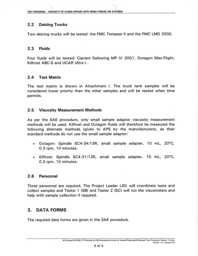
Transports         Transport                                                                       FORMULE DE DONNÉES POUR PUBLICATION
                Canada             Canada
 1.    No de la publication de Transports Canada                    2.    No de l’étude                                         3.    No de catalogue du destinataire

       TP 14445E                                                          5498-5501 (a-d)
 4.    Titre et sous-titre                                                                                                      5.    Date de la publication

       Evaluation of Type IV Fluids Applied Using Forced Air Assist Equipment                                                         Novembre 2005

                                                                                                                                6.    No de document de l’organisme exécutant

                                                                                                                                      CM1892.001
 7.    Auteur(s)                                                                                                                8.    No de dossier - Transports Canada

       Stephanie Bendickson                                                                                                           2450-BP-14
 9.    Nom et adresse de l’organisme exécutant                                                                                  10.   No de dossier - TPSGC

       APS Aviation Inc.                                                                                                              MTB-3-01379
       634, rue Saint-Jacques, 4ième étage                                                                                      11.   No de contrat - TPSGC ou Transports Canada
       Montréal (Québec) H3C 1C7
                                                                                                                                      T8200-033534
 12.   Nom et adresse de l’organisme parrain                                                                                    13.   Genre de publication et période visée

       Centre de développement des transports                                                                                         Final
       Transports Canada
       800, Boul. René-Lévesque Ouest, Bureau 600                                                                               14.   Agent de projet

       Montréal (Québec) H3B 1X9                                                                                                      Antoine Lacroix pour Barry Myers
 15.   Remarques additionnelles (programmes de financement, titres de publications connexes, etc.)

       Plusieurs rapports de recherche sur des essais de technologies de dégivrage et d’antigivrage ont été produits au cours des hivers précédents pour le
       compte de Transports Canada. Ils sont disponibles au Centre de développement des transports. Neuf rapports (dont celui-ci) ont été rédigés dans le
       cadre du programme de recherche de cet hiver. Leur objet apparaît à l’avant-propos. Ce projet était coparrainé par la Federal Aviation Administration.
 16.   Résumé

       Des systèmes à air forcé sont mis au point depuis plus de cinq ans. L’une des principales préoccupations soulevées est
       la possibilité que les valeurs actuelles des durées d’efficacité ne soient pas valides lorsque des liquides de types II ou IV
       sont appliqués à l’aide de systèmes à air forcé. Des tests ont été effectués par FedEx en 2003-2004 afin de comparer la
       viscosité des liquides appliqués à l’aide de systèmes à air forcé à la viscosité des liquides appliqués de façon traditionnelle.
       Les résultats obtenus ont démontré que l’application de liquides à l’aide de systèmes à air forcé entraîne une diminution
       de leur viscosité supérieure à celle observée lors d’une application traditionnelle.

       Deux changements ont été apportés à la procédure relative aux liquides de types II/IV à la suite de la séance d’essai
       infructueuse de 2003-2004. Premièrement, le critère d’approbation a été modifié : la viscosité des liquides appliqués à
       l’aide de systèmes à air forcé est désormais comparée à leur plus basse viscosité sur l’aile plutôt qu’à leur viscosité lors
       d’une application traditionnelle. Deuxièmement, une condition stipulant que des tests préliminaires établissant la
       configuration de l’équipement doivent être menés avant son évaluation avec des liquides précis a été ajoutée.

       À l’aide de cette nouvelle procédure, FedEx a mené des tests en janvier 2005 avec quatre liquides de type IV et deux
       camions de dégivrage à air forcé. L’un des quatre liquides évalués a pu être approuvé pour utilisation, et ce, sans
       restrictions de viscosité. Deux liquides ont pu être approuvés pour utilisation à l’aide de systèmes à air forcé, mais avec
       des restrictions sur les viscosités livrables. Un liquide n’a pas pu être approuvé, l’échantillon envoyé pour essai n’étant
       pas conforme aux critères d’évaluation.

       À la suite de la séance d’essai, il a été conclu que la nouvelle procédure constituait une amélioration par rapport à sa
       version précédente, et que ces changements devraient continuer d’y figurer dans le cadre des tests à venir.

 17.   Mots clés                                                                                      18.   Diffusion

       Viscosité, air forcé, assisté par air, durées d’efficacité,                                          Le Centre de développement des transports dispose
       liquides, plus basse viscosité sur l’aile                                                            d’un nombre limité d’exemplaires.

 19.   Classification de sécurité (de cette publication)            20.   Classification de sécurité (de cette page)     21.   Déclassification     22.   Nombre        23.   Prix
                                                                                                                               (date)                     de pages
       Non classifiée                                                     Non classifiée                                             —                  xviii, 38                    —
                                                                                                                                                         ann.
CDT/TDC 79-005
Rev. 96

                                                                                                 vi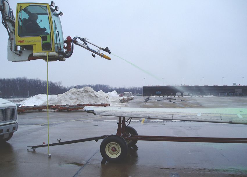
EXECUTIVE SUMMARY

EXECUTIVE SUMMARY

Under contract to the Transportation Development Centre (TDC) of Transport
Canada (TC), with support from the Federal Aviation Administration (FAA), APS
Aviation Inc. (APS) has undertaken a research program to further advance aircraft
ground de/anti-icing technology. In recent years one of the research activities has
been the advancement of forced air deicing systems.

Background

Forced air systems have been in development for more than five years. In
1999-2000, APS wrote TC report, TP 13664E, Safety Issues and Concerns of
Forced Air Systems (1), which first documented possible safety issues that could
arise from their use in field operations. One concern was that current holdover time
values would not be valid when Type II or Type IV fluids were applied with forced
air systems.

Fluid viscosity was agreed to be an appropriate method of evaluating holdover
times. Testing by FedEx in 2003-04 compared the viscosity of fluid applied with
forced air to the viscosity of fluid applied with a conventional system. The tests
showed that fluid viscosity decreased more with a forced air application than with
a conventional application.

Two changes were made to the Type II/IV procedure following the unsuccessful
2003-04 test session. First, the approval criterion was changed: the viscosity of
fluid applied with the forced air system would be compared to the lowest on-wing
viscosity (LOWV) instead of to the conventional application viscosity. Second, a
requirement was added to the procedure in which the equipment settings had to be
fixed prior to the evaluation of the equipment with specific fluids.

FedEx conducted a one-week test session in early January 2005 to establish the
fixed setup it would test. Two weeks later, a second test session evaluated four
FedEx forced air systems (two deicing trucks, each evaluated with and without an
air sleeve) and four anti-icing fluids.

Data/Analysis

Tests took place in clear conditions with fluid cooled to -5°C. Fluid was applied to
a JetStar wing using the forced air systems. Samples were immediately collected
off the wing and brought to the lab for viscosity measurement. Samples of the fluid
tote viscosity were also measured.

                           M:\Projects\PM1892 (TC Deicing 04-05)\Reports\Forced Air\Final Version 1.0\TP 14445E Final Version 1.0.docx
                                                                                                             Final Version 1.0, May 20
                                                    vii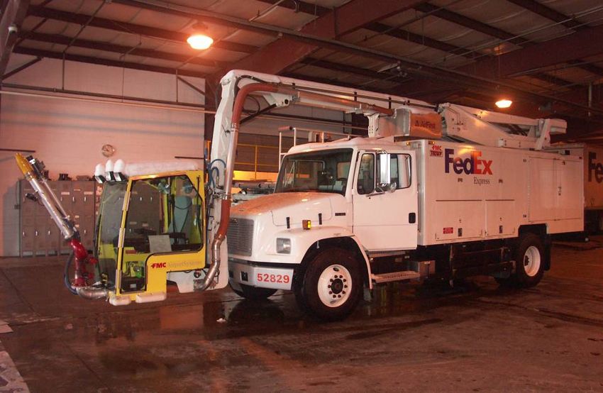
EXECUTIVE SUMMARY

The viscosity of the tested fluids was compared to the LOWV. Using a formula
given in the test protocol, the lowest acceptable delivered viscosity (LADV) was
determined. The LADV is the lowest viscosity a fluid can have that ensures the
viscosity will not go below the LOWV when applied with forced air.

One of the four tested fluids had an LADV below the low end of the standard
delivered viscosity range and therefore could be approved for use without
restrictions on viscosity. Two fluids had LADVs above the low end of the standard
delivered viscosity range, but below the high end, and therefore could be approved
for use with forced air with limitations on delivered viscosities. One fluid could not
be approved as the sample sent for testing did not conform to the test
requirements.

Conclusions
Two major changes were made to the Type II/IV forced air test procedure in
2004-05. The first change was the addition of a requirement to conduct pre-tests
to fix the equipment setup. This proved to be a necessary and valuable addition as
it ensures test results are applicable to actual operations and assists operators in
determining appropriate setups prior to the actual test session. The second change
was to the acceptance criterion: the viscosities of fluids applied with forced air are
now compared to the LOWV, rather than to viscosities achieved with fluids applied
with conventional systems. This method seems to be a reasonable approach for
evaluating forced air systems.

Kilfrost ABC-S can be accepted for use with both the FMC Tempest II (TII) deicing
truck and the FMC LMD 2000 (LMD) deicing truck, both with or without the air
sleeve, with no restrictions on delivered viscosity. Octagon Max-Flight 04 and
Clariant Safewing 2001 can be accepted for use with both the TII and LMD deicing
trucks, with or without the air sleeve. However, the minimum acceptable viscosity
of delivered fluid for these two fluids is higher than that of a fluid accepted for use
with conventional systems. Dow UCAR Ultra+ cannot be accepted for use with
forced air systems since the manufacturer provided fluid that did not conform to
the test protocol requirements.

The presence of an air sleeve does not have a significant impact on the change in
viscosity caused by forced air application. Neither deicing truck used in the tests
was found to consistently cause more degradation to fluid viscosity than the other.

Recommendations
It is recommended that regulatory bodies continue to be involved in forced air
evaluations and be present at test sessions. A laboratory such as APS should
continue to act as an independent lab.

                            M:\Projects\PM1892 (TC Deicing 04-05)\Reports\Forced Air\Final Version 1.0\TP 14445E Final Version 1.0.docx
                                                                                                              Final Version 1.0, May 20
                                                     viii
SOMMAIRE
SOMMAIRE
En vertu d’un contrat avec le Centre de développement des transports (CDT) de
Transports Canada (TC) et avec l’appui de la Federal Aviation Administration (FAA),
APS Aviation Inc. (APS) a entrepris un programme de recherche visant à faire
progresser les technologies associées au dégivrage et à l’antigivrage d’aéronefs au
sol. Au cours des dernières années, l’une des activités de recherche s’est
concentrée sur le développement de systèmes de dégivrage à air forcé.
Contexte
Des systèmes à air forcé sont mis au point depuis plus de cinq ans. En 1999-2000,
APS a rédigé pour TC le rapport TP 13664E, Safety Issues and Concerns of Forced
Air Systems (1), le premier à rendre compte des problèmes de sécurité pouvant
découler de l’utilisation des systèmes à air forcé lors d’opérations sur le terrain.
L’une des préoccupations soulevées était que les valeurs des durées d’efficacité du
moment ne seraient pas valides lors de l’application des liquides de types II ou IV à
l’aide de systèmes à air forcé.
Il a été convenu que la viscosité des liquides s’avérait une méthode d’évaluation
des durées d’efficacité appropriée. Des tests ont été effectués par FedEx en
2003-2004 afin de comparer la viscosité des liquides appliqués à l’aide de
systèmes à air forcé à la viscosité des liquides appliqués de façon traditionnelle. Les
résultats obtenus ont démontré que l’application de liquides à l’aide de systèmes à
air forcé entraîne une diminution de leur viscosité supérieure à celle observée lors
d’une application traditionnelle.
Deux changements ont été apportés à la procédure relative aux liquides de
types II/IV à la suite de la séance d’essai infructueuse de 2003-2004.
Premièrement, le critère d’approbation a été modifié : la viscosité des liquides
appliqués à l’aide de systèmes à air forcé est désormais comparée à leur plus basse
viscosité sur l’aile plutôt qu’à leur viscosité lors d’une application traditionnelle.
Deuxièmement, une condition stipulant que les paramètres de l’équipement doivent
être établis avant son évaluation avec des liquides précis a été ajoutée à la
procédure.
FedEX a organisé une séance d’essai d’une semaine au début de janvier 2005 dans
le but de déterminer la configuration définitive qui serait évaluée. Une seconde
séance a été tenue deux semaines plus tard, cette fois afin d’évaluer quatre
systèmes à air forcé de FedEx (deux camions de dégivrage, chacun analysé avec et
sans manchon pneumatique) et quatre liquides d’antigivrage.
M:\Projects\PM1892 (TC Deicing 04-05)\Reports\Forced Air\Final Version 1.0\TP 14445E Final Version 1.0.docx
Final Version 1.0, May 20
ixSOMMAIRE
Données/analyse
Les essais ont été menés dans des conditions claires, avec des liquides refroidis à
-5°C. Ces liquides ont été appliqués sur une aile Jetstar à l’aide de systèmes à air
forcé. Des échantillons ont immédiatement été recueillis sur l’aile et apportés au
laboratoire pour en mesurer la viscosité. Des échantillons de la viscosité des
liquides dans les récipients ont également été mesurés.
La viscosité des liquides testés a été comparée à la plus basse viscosité sur l’aile
(LOWV). À l’aide d’une formule présentée dans le protocole d’essai, la plus basse
viscosité livrable (LADV) a été établie. La plus basse viscosité livrable constitue la
plus basse viscosité que peut avoir un liquide sans descendre sous la plus basse
viscosité sur l’aile lors d’une application à l’aide de systèmes à air forcé.
L’un des quatre liquides évalués présentait une plus basse viscosité livrable se
situant au-dessous de la valeur inférieure de la fourchette de viscosité livrable
standard, et a donc pu être approuvé pour utilisation sans restrictions de viscosité.
Deux liquides présentaient une plus basse viscosité livrable se situant au-dessus de
la valeur inférieure de la fourchette de viscosité livrable standard, mais au-dessous
de sa valeur supérieure, et ont donc pu être approuvés pour utilisation à l’aide de
systèmes à air forcé, mais avec des restrictions sur les viscosités livrables. Un
liquide n’a pas pu être approuvé, l’échantillon envoyé pour essai n’étant pas
conforme aux critères d’évaluation.
Conclusions
Deux changements majeurs ont été apportés à la procédure d’essai relative aux
liquides de types II/IV appliqués à l’aide de systèmes à air forcé en 2004-2005. Le
premier changement a été l’ajout d’une condition stipulant que des tests
préliminaires établissant la configuration de l’équipement doivent être menés. Cet
ajout s’est avéré nécessaire et utile, puisqu’il permet d’assurer que les résultats des
tests s’appliquent aux opérations réelles et qu’il aide les exploitants aériens à
déterminer les paramètres appropriés avant que ne soit menée la séance
proprement dite. Le second changement concerne le critère d’approbation : la
viscosité des liquides appliqués à l’aide de systèmes à air forcé est désormais
comparée à leur plus basse viscosité sur l’aile plutôt qu’à leur viscosité lors d’une
application traditionnelle. Cette méthode apparaît comme une approche raisonnable
pour l’évaluation des systèmes à air forcé.
Le liquide Kilfrost ABC-S peut être accepté pour utilisation avec les camions de
dégivrage FMC Tempest II (TII) et FMC LMD 2000 (LMD), avec ou sans manchon
pneumatique, et ce, sans restrictions sur les viscosités livrables. Les liquides
Octagon Max-Flight 04 et Clariant Safewing 2001 peuvent être acceptés pour
M:\Projects\PM1892 (TC Deicing 04-05)\Reports\Forced Air\Final Version 1.0\TP 14445E Final Version 1.0.docx
Final Version 1.0, May 20
xSOMMAIRE
utilisation avec les camions de dégivrage TII et LMD, avec ou sans manchon
pneumatique. La viscosité livrable minimale pour ces deux liquides s’avère
cependant plus élevée que celle d’un liquide accepté pour utilisation avec des
systèmes traditionnels. Le liquide Dow UCAR Ultra+ ne peut pas être accepté pour
utilisation avec des systèmes à air forcé, son fabricant ayant fourni un liquide non
conforme aux critères du protocole d’essai.
La présence d’un manchon pneumatique n’exerce pas une influence significative
sur le changement de viscosité causé par une application à l’aide de systèmes à air
forcé. Aucun des deux camions de dégivrage utilisés dans le cadre des tests n’a été
systématiquement associé à une dégradation de la viscosité des liquides supérieure
à l’autre.
Recommandations
Il est recommandé que les organismes de réglementation continuent de participer
aux évaluations des systèmes à air forcé et de prendre part aux séances d’essai.
Un laboratoire comme APS devrait continuer d’agir à titre de laboratoire
indépendant.
M:\Projects\PM1892 (TC Deicing 04-05)\Reports\Forced Air\Final Version 1.0\TP 14445E Final Version 1.0.docx
Final Version 1.0, May 20
xiThis page intentionally left blank.
xiiTABLE OF CONTENTS
CONTENTS Page
1. INTRODUCTION ........................................................................................................... 1
1.1 Background ......................................................................................................... 1
1.2 Developments in 2004-05...................................................................................... 2
1.3 Objective ............................................................................................................. 3
2. METHODOLOGY........................................................................................................... 5
2.1 Procedure ............................................................................................................ 5
2.2 Test Site ............................................................................................................. 6
2.3 Equipment ........................................................................................................... 6
2.3.1 Test Surface ............................................................................................. 6
2.3.2 Forced Air Systems .................................................................................... 7
2.4 Refrigerated Truck ................................................................................................ 7
2.5 Fluids .................................................................................................................. 8
2.5.1 Viscosity Measurement Equipment ............................................................... 8
2.6 Samples Collected ................................................................................................ 9
2.7 Personnel ............................................................................................................ 9
3. DATA ....................................................................................................................... 17
3.1 Summary of Daily Testing .................................................................................... 17
3.1.1 January 24th, 2005 ................................................................................. 17
3.1.2 January 25th, 2005 ................................................................................. 17
3.1.3 January 26th, 2005 ................................................................................. 17
3.2 Acceptance of Fluid Samples................................................................................ 17
3.3 Fluid Viscosity .................................................................................................... 18
3.4 Fluid Density ...................................................................................................... 22
3.5 Fluid Thickness .................................................................................................. 23
4. ANALYSIS ................................................................................................................. 27
4.1 Acceptance of Fluids with Specific Forced Air Systems ............................................ 27
4.1.1 Lowest Acceptable Delivered Viscosity ....................................................... 27
4.1.2 Example of LADV Calculation .................................................................... 27
4.1.3 LADV of Tested Fluids.............................................................................. 28
4.1.4 Acceptable Delivery Viscosity Ranges ......................................................... 29
4.1.5 Implication of Kilfrost ABC-S Viscosity Delivery Range Change....................... 30
4.2 Comparison of Tempest II and LMD 2000 Deicing Trucks ......................................... 31
4.3 Effect of Air Sleeve ............................................................................................. 32
5. CONCLUSIONS .......................................................................................................... 33
5.1 Procedure .......................................................................................................... 33
5.2 Fluid Acceptance ................................................................................................ 33
6. RECOMMENDATIONS ................................................................................................. 35
REFERENCES .................................................................................................................... 37
M:\Projects\PM1892 (TC Deicing 04-05)\Reports\Forced Air\Final Version 1.0\TP 14445E Final Version 1.0.docx
Final Version 1.0, May 20
xiiiTABLE OF CONTENTS
LIST OF APPENDICES
A Transportation Development Centre Work Statement Excerpt – Aircraft & Anti-Icing Fluid
Winter Testing 2003-05
B Test Procedures
C Fluid Manufacturer Fluid Certificates of Analysis
D List of Attendees – FedEx Forced Air Test Session January 24 to 26, 2005
M:\Projects\PM1892 (TC Deicing 04-05)\Reports\Forced Air\Final Version 1.0\TP 14445E Final Version 1.0.docx
Final Version 1.0, May 20
xivLIST OF FIGURES, TABLES AND PHOTOS
LIST OF FIGURES Page
Figure 3.1: Viscosity of Kilfrost ABC-S Samples ................................................................... 20
Figure 3.2: Viscosity of Dow UCAR Ultra+ Samples ............................................................. 20
Figure 3.3: Viscosity of Octagon Max-Flight 04 Samples ....................................................... 21
Figure 3.4: Viscosity of Clariant Safewing 2001 Samples ...................................................... 21
LIST OF TABLES Page
Table 3.1:
Tote Viscosities ................................................................................................ 18
Table 3.2:
Log of Tests ..................................................................................................... 19
Table 3.3:
Fluid Densities .................................................................................................. 22
Table 3.4:
Fluid Thickness after Application ......................................................................... 23
Table 4.1:
Lowest Acceptable Delivered Fluid Viscosities ....................................................... 28
Table 4.2:
Acceptable Delivery Viscosity Ranges for use with Forced Air Systems .................... 29
Table 4.3:
Decrease in Viscosity of Fluids Applied with Tempest II and LMD 2000 Deicing
Trucks ............................................................................................................. 31
Table 4.4: Decrease in Viscosity of Fluids Applied with and without Air Sleeve ......................... 32
LIST OF PHOTOS Page
Photo 2.1: Position of Nozzle Relative to Test Surface ........................................................... 11
Photo 2.2: Sample Collection ............................................................................................. 11
Photo 2.3: APS Mobile Viscosity Laboratory ........................................................................ 12
Photo 2.4: Transport Canada JetStar Wing .......................................................................... 12
Photo 2.5: FMC Tempest II Deicing Truck............................................................................ 13
Photo 2.6: FMC LMD 2000 Deicing Truck ........................................................................... 13
Photo 2.7: Air Sleeve ....................................................................................................... 14
Photo 2.8: Fluid Storage in Refrigerated Truck ..................................................................... 14
Photo 2.9: Brookfield LV DV-I+ Digital Viscometer ............................................................... 15
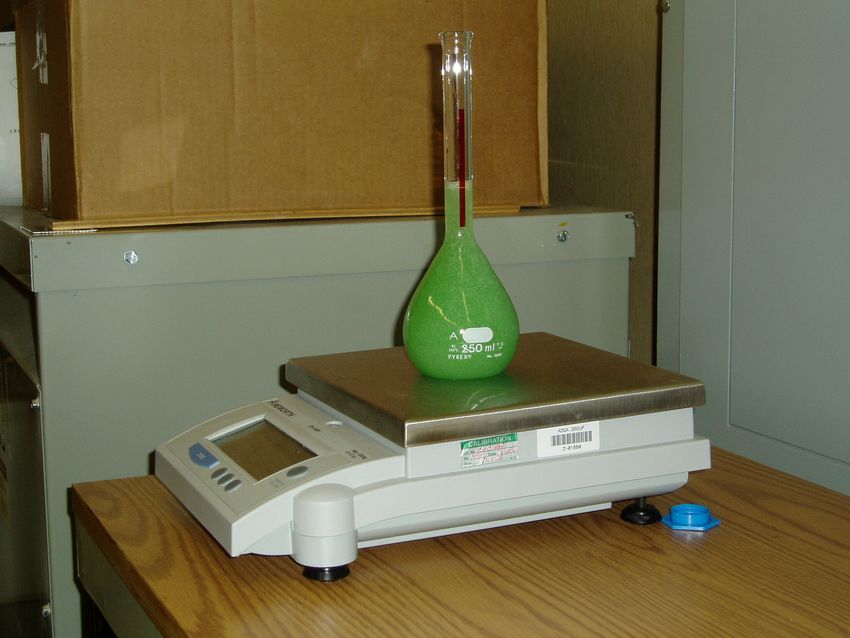
Photo 3.1: Measuring Fluid Density .................................................................................... 25
Photo 3.2: Measuring Fluid Thickness ................................................................................. 25
M:\Projects\PM1892 (TC Deicing 04-05)\Reports\Forced Air\Final Version 1.0\TP 14445E Final Version 1.0.docx
Final Version 1.0, May 20
xvThis page intentionally left blank.
xviGLOSSARY
GLOSSARY
APS APS Aviation Inc.
FAA Federal Aviation Administration
LADV Lowest Acceptable Delivered Viscosity
LMD LMD 2000
LOWV Lowest On-Wing Viscosity
OAT Outside Air Temperature
SAE Society of Automotive Engineers
TII Tempest II
TC Transport Canada
TDC Transportation Development Centre
M:\Projects\PM1892 (TC Deicing 04-05)\Reports\Forced Air\Final Version 1.0\TP 14445E Final Version 1.0.docx
Final Version 1.0, May 20
xviiThis page intentionally left blank.
xviii1. INTRODUCTION
1. INTRODUCTION
Under winter precipitation conditions, aircraft are cleaned with a freezing point
depressant fluid and protected against further accumulation by an additional
application of such a fluid, possibly thickened to extend the protection time.
Aircraft ground deicing had, until recently, never been researched and there is still
an incomplete understanding of the hazard and of what can be done to reduce the
risks posed by the operation of aircraft in winter precipitation conditions. This
"winter operations contaminated aircraft – ground" program of research is aimed at
overcoming this lack of knowledge.
Since the early 1990s, the Transportation Development Centre (TDC) of Transport
Canada (TC) has managed and conducted de/anti-icing related tests at various sites
in Canada; it has also coordinated worldwide testing and evaluation of evolving
technologies related to de/anti-icing operations with the co-operation of the United
States Federal Aviation Administration (FAA), the National Research Council
Canada (NRC), Atmospheric Environment Services, several major airlines, and
deicing fluid manufacturers. The TDC is continuing its research, development,
testing and evaluation program.
Under contract to the TDC, with support from the Federal Aviation Administration
(FAA), APS Aviation Inc. (APS) has undertaken research program to further
advance aircraft ground de/anti-icing technology. In recent years, one of these
research activities has been the advancement of forced air systems.
1.1 Background
Forced air systems have been in development for more than five years. In
1999-2000, APS produced the TC report, TP 13664E, Safety Issues and Concerns
of Forced Air Systems (1), which first documented possible safety issues that
could arise from their use in field operations. The Society of Automotive Engineers
(SAE) G-12 Aircraft Ground Deicing Equipment Subcommittee subsequently
proposed a Forced Air Working Group to focus on the project.
Over the next several winters, the work group developed test procedures for use
with forced air systems. A Type I fluid procedure was published in
November 2001. This procedure provides guidance to operators wanting to use
forced air with Type I fluid as the first step in a two-step de/anti-icing operation.
Holdover times are not affected by forced air system use in this situation, as the
Type I forced air application is followed by a conventional application of Type II or
Type IV fluid.
M:\Projects\PM1892 (TC Deicing 04-05)\Reports\Forced Air\Final Version 1.0\TP 14445E Final Version 1.0.docx
Final Version 1.0, May 20
11. INTRODUCTION
However, concern arose that the current holdover time values would not be valid
when Type II or Type IV fluids were applied with forced air systems. The purpose
of the Type II/IV procedure was therefore to evaluate the effect of forced air
applications on holdover times of Type II/IV fluids. The Type II/IV procedure went
through several revisions, as the best way to evaluate the outcome was debated. A
detailed account of this history is given in the TC report, TP 14380E, A Protocol
for Testing Fluids Applied with Forced Air Systems (2).
Measuring fluid viscosity was eventually accepted as an appropriate method of
evaluating holdover times. The viscosity of fluids applied with forced air deicing
systems would be compared to the viscosity of fluids applied with conventional
deicing systems. Each forced air system/fluid combination would be approved by
the regulators individually if the viscosities were similar. APS assisted in tests
conducted by FedEx in the winter of 2003-04 using this procedure. However,
unlike preliminary tests which showed similar fluid viscosities between the
conventional and forced air system applications, the tests showed fluid viscosity
decreased more with a forced air application than with a conventional application.
These tests are documented in TP 14380E (2).
1.2 Developments in 2004-05
Two changes were made to the Type II/IV procedure following the 2003-04 test
session. First, it was recognized that the standard for accepting forced air
equipment may have been too rigid. Several fluids that did not meet the standard in
2003-04 testing had viscosities above the lowest on-wing viscosity (LOWV), which
is the standard required of fluids applied with conventional systems. The approval
criterion was changed: the viscosity of the fluid applied with the forced air system
would be compared to the LOWV instead of to the conventional application
viscosity.
Second, it was theorized that settings on the forced air equipment could have led
to the varying results seen in 2003-04, and that changing the settings could
eliminate the variability and minimize the effect the application had on fluid
viscosity. To account for this, a requirement was added to the procedure in which
the settings had to be “fixed” prior to evaluation of the equipment with specific
fluids. Once tested, and if the fluid met the approval criterion, only the setup tested
would be accepted by the regulatory authorities.
In early January 2005, FedEx conducted a one-week test session at their facility in
Pittsburgh, Pennsylvania to find the “optimal” equipment setup to use with their
forced air systems. The optimal setup would cause the least amount of shearing to
the anti-icing fluid without causing a hindrance to the deicing operation. APS was
present at this test session to measure fluid viscosities.
M:\Projects\PM1892 (TC Deicing 04-05)\Reports\Forced Air\Final Version 1.0\TP 14445E Final Version 1.0.docx
Final Version 1.0, May 20
21. INTRODUCTION
Two weeks later, a second test session was held in order to evaluate two FedEx
deicing trucks and four anti-icing fluids with the fixed setup selected at the
previous test session. This report details this second test session.
1.3 Objective
APS’ objective in forced air research is to assist the SAE ground equipment
committee in evaluating forced air systems. This includes updating test procedures
as necessary, and participating in operator field tests of de/anti-icing fluids.
At the FedEx field tests, APS’ primary objective was to measure in-situ viscosities
of the tested fluids and compare them to the standards given by the regulatory
authorities.
The scope of work for this project is outlined in an excerpt from the TDC work
statement provided in Appendix A.
M:\Projects\PM1892 (TC Deicing 04-05)\Reports\Forced Air\Final Version 1.0\TP 14445E Final Version 1.0.docx
Final Version 1.0, May 20
3This page intentionally left blank.
42. METHODOLOGY
2. METHODOLOGY
2.1 Procedure
In November 2004, a meeting was held to discuss changes to the Type II/IV forced
air test procedure published in December 2003. The meeting was attended by APS,
FedEx, the FAA and FMC. Following the meeting, APS incorporated several
changes into the procedure.
1) Ambient Temperature: A requirement was added stipulating that testing take
place at an ambient temperature of less than 0°C.
2) Approval Criterion: The approval criterion was changed so the viscosity of
the tested fluids was compared to the fluid’s LOWV.
3) Fixed Setup: A requirement was added that the variable settings on the
forced air system be “fixed” and that all tests be conducted with the fixed
setup.
Key components of the final version of the procedure include:
• Tests take place in clear (no precipitation) conditions, or in a place sheltered
from all precipitation;
• Tests take place below 0°C;
• An aircraft wing is used as a test bed; alternate surfaces are not acceptable;
• Initial viscosity of test fluid is in the middle of the viscosity delivery range;
• Viscosity measurements are made immediately after application;
• The angle of fluid spray and the distance between nozzle and wing are fixed;
• The test surface is cleaned between applications of test fluids; and
• The deicing truck tank is cleaned between test fluids.
At the FedEx test session, the activities below were carried out to meet the
procedural requirements.
• To avoid contamination from natural precipitation, most fluids were applied
to the wing inside the FedEx hangar.
M:\Projects\PM1892 (TC Deicing 04-05)\Reports\Forced Air\Final Version 1.0\TP 14445E Final Version 1.0.docx
Final Version 1.0, May 20
52. METHODOLOGY
• The position of the truck relative to the test surface was measured prior to
each fluid application. The setup is shown in Photo 2.1. It should be noted
that the horizontal distance was 2.9 m (9.5 ft.) for several tests.
• Immediately following fluid application, fluid samples were collected from the
wing (see Photo 2.2). Care was taken not to shear the samples as they were
collected.
• APS’ mobile viscosity laboratory (see Photo 2.3) was brought in from
Montreal to enable immediate testing of fluid viscosity.
• After each fluid application, the wing was cleaned with Type I fluid. After
the wing was deiced, the Type I fluid was blown off the wing using forced
air. This procedure prevented the test fluid from being contaminated by
either the previous test fluid or Type I fluid. The Type IV test fluid was then
applied and squeegeed off; this ensured that the only residue on the wing
was from the test fluid. Following this process, the test fluid was reapplied
using forced air assist.
The final version of the Type II/IV procedure, Version 4.0, is included in
Appendix B. In addition, a test matrix was developed specifically for the FedEx
tests. The test matrix was published in a separate procedure, which is also
included in Appendix B.
2.2 Test Site
Tests were conducted at the FedEx hangar at the Pittsburgh International Airport in
Pittsburgh, Pennsylvania. The majority of tests were conducted inside the hangar.
Several tests were conducted outside the hangar in clear conditions.
2.3 Equipment
2.3.1 Test Surface
A Lockheed JetStar wing owned by TC was transported from Montreal to
Pittsburgh and used as a test bed. The same wing was used in the 2003-04 FedEx
forced air tests in Rochester, New York. The shipment was arranged by APS and
funded by FedEx. The wing is shown in Photo 2.4.
M:\Projects\PM1892 (TC Deicing 04-05)\Reports\Forced Air\Final Version 1.0\TP 14445E Final Version 1.0.docx
Final Version 1.0, May 20
62. METHODOLOGY
2.3.2 Forced Air Systems
Two FMC deicing trucks were tested: the FMC Tempest II (TII) and the FMC LMD
2000 (LMD). These trucks are shown in Photos 2.5 and 2.6, respectively.
Prior to the test session, preliminary tests were carried out by FedEx to determine
the optimal equipment setup. Several variables were examined. These included fluid
flow rate, airflow pressure, nozzle position, and presence of an air sleeve.
The preliminary tests were conducted with Kilfrost ABC-S because it experienced
the most viscosity degradation when applied with forced air in the 2003-04 tests.
It was therefore assumed that results of testing with this fluid would give the
worst-case results.
The optimal setup was found to be:
• Fluid flow rate: 94.6 lpm (litres/minute) or 25 gpm (grams/minute);
• Airflow pressure: 41.4 kPa (6 psi); and
• Nozzle position: 17.8 cm (7”) between centre points of air and fluid nozzles,
achieved by inserting a 7.6 cm (3”) separator.
Because testing with the air sleeve sometimes gave higher viscosities and
sometimes gave lower viscosities, it was decided tests would be conducted both
with and without the air sleeve so that both setups could potentially be certified.
The air sleeve is shown in Photo 2.7.
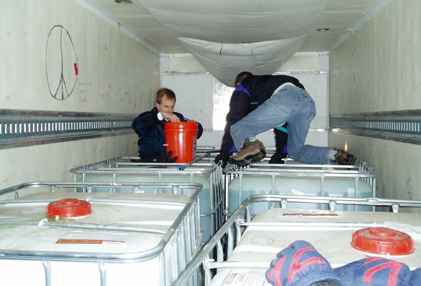
2.4 Refrigerated Truck
There was concern that during the test session in Pittsburgh the outside air
temperature (OAT) would not be lower than 0°C as required in the procedure.
FedEx obtained approval from the FAA to store the fluids at -5°C and to test the
cooled fluids even if the temperature went slightly above 0°C. This was also seen
as a way to equalize the test conditions for all of the fluids. To cool the fluids,
FedEx brought in a refrigerated truck which was kept at -5°C. Fluids were placed
in the refrigerated truck several days before the test session, and remained there
until they were moved to the deicing trucks for testing. A picture of the fluids
stored in the refrigerated truck is shown in Photo 2.8.
M:\Projects\PM1892 (TC Deicing 04-05)\Reports\Forced Air\Final Version 1.0\TP 14445E Final Version 1.0.docx
Final Version 1.0, May 20
72. METHODOLOGY
2.5 Fluids
Four Type IV fluids were tested: Kilfrost ABC-S, Dow UCAR Ultra+, Octagon
Max-Flight 04, and Clariant Safewing MP IV 2001. All of these fluids are propylene
glycol based, with the exception of Dow UCAR Ultra+, which is ethylene glycol
based.
Fluid manufacturers were asked to send fluids with viscosities in the middle of their
respective production ranges. The Clariant fluid did not meet this requirement;
however, a different batch of fluid on-hand at FedEx’s facility in Pittsburgh was
closer to the required viscosity, and was substituted for the test fluid. The Dow
UCAR Ultra+ sample was significantly higher than its usual production range. The
sample was used, as no other samples were available. Fluid acceptance is
discussed in more detail in Subsection 3.2.
The fluid manufacturer fluid certificates of analysis are included in Appendix C.
2.5.1 Viscosity Measurement Equipment
Two Brookfield LV DV-I+ digital viscometers were used to measure fluid viscosity
(see Photo 2.9). Each viscometer was equipped with a small sample adaptor and
attached to a temperature-circulating bath. Prior to testing, viscometer accuracy
was checked using the manufacturer’s stated procedure for small sample adaptor
calibration (given in Brookfield operating manual no. M/92-021-J1297, page 30).
Whenever possible, fluid manufacturer viscosity measurement methods were used.
Due to time constraints it was not feasible to use methods requiring large samples.
In these cases fluid manufacturers recommended alternate small sample methods
and provided a conversion formula or factor between the two methods.
The following viscosity measurement methods were used:
• Kilfrost ABC-S: Spindle 31, 10 mL, 20°C, 0.3 rpm, 10 minutes;
• Dow UCAR Ultra+: Spindle 31, 10 mL, 0°C, 0.3 rpm, 10 minutes;
• Octagon Max-Flight: Spindle 34, 10 mL, 20°C, 0.3 rpm, 10 minutes; and
• Clariant Safewing 2001: Spindle 34, 10 mL, 20°C, 0.3 rpm, 15 minutes.
All samples were centrifuged before viscosity tests were conducted. As per
standard viscosity measurement procedure, two measurements were taken per
sample. To eliminate any discrepancy between the two viscometers, one
M:\Projects\PM1892 (TC Deicing 04-05)\Reports\Forced Air\Final Version 1.0\TP 14445E Final Version 1.0.docx
Final Version 1.0, May 20
82. METHODOLOGY
measurement was done on each viscometer. The viscosity reported is an average
of the two measurements.
2.6 Samples Collected
For each fluid and truck combination, four viscosity samples were collected: fluid
tote, truck tank, on-wing (sprayed with air sleeve), and on-wing (sprayed without
air sleeve). In most cases, fluid from the same tote was loaded into both (TII and
LMD) deicing trucks. In these cases only one fluid tote sample was taken.
Viscosity of the fluid tote samples was measured at the beginning of the test
session. Viscosity of the on-wing samples was measured immediately following
application. Truck tank samples were collected in case on wing viscosities were not
as expected, and some type of contamination in the truck was suspected. This did
not occur so the samples were never tested.
2.7 Personnel
The Pittsburgh test session was organized by FedEx, who invited representatives
from TC, the FAA, SAE, truck manufacturers and various fluid manufacturers to
observe the tests. APS was invited to act as an independent laboratory for the
tests. A list of attendees is included in Appendix D.
Two APS technicians were required to run the mobile viscosity laboratory. In
addition, a project manager was present to offer guidance and support to all parties
during the test session.
M:\Projects\PM1892 (TC Deicing 04-05)\Reports\Forced Air\Final Version 1.0\TP 14445E Final Version 1.0.docx
Final Version 1.0, May 20
9This page intentionally left blank.
102. METHODOLOGY
Photo 2.1: Position of Nozzle Relative to Test Surface
1.45 m
(4.75’)
24º
3.2 m
(10.5’)
Photo 2.2: Sample Collection
M:\Projects\PM1892 (TC Deicing 04-05)\Reports\Forced Air\Final Version 1.0\TP 14445E Final Version 1.0.docx
Final Version 1.0, May 20
112. METHODOLOGY
Photo 2.3: APS Mobile Viscosity Laboratory
Photo 2.4: Transport Canada JetStar Wing
M:\Projects\PM1892 (TC Deicing 04-05)\Reports\Forced Air\Final Version 1.0\TP 14445E Final Version 1.0.docx
Final Version 1.0, May 20
122. METHODOLOGY
Photo 2.5: FMC Tempest II Deicing Truck
Photo 2.6: FMC LMD 2000 Deicing Truck
M:\Projects\PM1892 (TC Deicing 04-05)\Reports\Forced Air\Final Version 1.0\TP 14445E Final Version 1.0.docx
Final Version 1.0, May 20
132. METHODOLOGY
Photo 2.7: Air Sleeve
Photo 2.8: Fluid Storage in Refrigerated Truck
M:\Projects\PM1892 (TC Deicing 04-05)\Reports\Forced Air\Final Version 1.0\TP 14445E Final Version 1.0.docx
Final Version 1.0, May 20
142. METHODOLOGY
Photo 2.9: Brookfield LV DV-I+ Digital Viscometer
M:\Projects\PM1892 (TC Deicing 04-05)\Reports\Forced Air\Final Version 1.0\TP 14445E Final Version 1.0.docx
Final Version 1.0, May 20
15You can also read