LAYOUT CONSIDERATIONS ON THE 25GEV / 300KW BEAM DUMP OF THE XFEL PROJECT - DESY, AUGUST 2006, TESLA-FEL 2006-05
←
→
Page content transcription
If your browser does not render page correctly, please read the page content below
DESY, August 2006, TESLA-FEL 2006-05

Layout Considerations on the
 25GeV / 300kW Beam Dump
    of the XFEL Project
       M. Maslov1), M. Schmitz2), V. Sychev1)
 1)
      IHEP, Protvino, Russia, 2) DESY, Hamburg, Germany
Layout Considerations on the
                                 25GeV / 300kW Beam Dump
                                    of the XFEL Project
                                           M. Maslov1), M. Schmitz2), V. Sychev1)
                                     1)
                                          IHEP, Protvino, Russia, 2) DESY, Hamburg, Germany

                                                              Table of Contents
Abstract ...................................................................................................................................... 2
1    Introduction ........................................................................................................................ 2
2    Basic Layout Considerations.............................................................................................. 4
  2.1      Dump Core Material Selection................................................................................... 6
     2.1.1         Remarks on Spot Size Limit............................................................................... 9
  2.2      Radial Layout ........................................................................................................... 10
     2.2.1         Homogeneous radial Layout using one Material ............................................. 10
     2.2.2         Segmented radial Layout with Graphite Core.................................................. 14
  2.3      Back Stopper ............................................................................................................ 17
     2.3.1         Further Optimization of Dump Length ............................................................ 19
3    Baseline Design of the 25GeV / 300kW Dump with slow Sweeping.............................. 20
  3.1      Consequences of slow Sweeping a pulsed Beam..................................................... 23
     3.1.1         Reasonable Choice of Sweeping Frequency .................................................... 24
     3.1.2         Analysis of Stresses and Temperatures in the Dump....................................... 27
         3.1.2.1       Without Beam Sweep ............................................................................................................... 29
         3.1.2.2       With Beam Sweep .................................................................................................................... 30
  3.2      Heat Transfer at the Graphite-Copper Boundary ..................................................... 38
     3.2.1       Pressed Contact ................................................................................................ 38
     3.2.2       Brazed Contact ................................................................................................. 41
4    Alternative Dump Designs without slow Sweeping ........................................................ 41
  4.1      Pyrolitic Graphite Dump Core ................................................................................. 42
  4.2      Upstream Spoilers .................................................................................................... 45
  4.3      Segmented Graphite Dump Core ............................................................................. 48
     4.3.1       Energy Deposition in the segmented Dump Core............................................ 49
     4.3.2       Heat Extraction in the segmented Dump Core................................................. 53
     4.3.3       Longitudinal Temperature Profiles of the segmented Dump Layout............... 55
5    Comparative Summary..................................................................................................... 58
A Fundamentals on Energy Deposition in an Electron Dump............................................. 60
  A.1      Electromagnetic Shower (EMS) Development ........................................................ 60
     A.1.1       Longitudinal Characterization.......................................................................... 62
     A.1.2       Radial Characterization .................................................................................... 63
B Fundamentals on Dump Heating...................................................................................... 66
  B.1      Instantaneous Heating .............................................................................................. 69
  B.2      Heat Diffusion .......................................................................................................... 70
  B.3      Average Heating....................................................................................................... 70
References ................................................................................................................................ 72

                                                                            1
Abstract
           The European X-Ray Free Electron Laser (XFEL) project, which is currently under
       design at DESY, requires 3 beam dumps downstream of the accelerator. By means of
       energy deposition, temperature and mechanical stress calculations the layout of a solid
       edge cooled beam dump is presented. This dump is able to withstand a high cyclic
       impact, as induced by each subsequent bunch train of up to 2.5⋅1013 electrons in
       combination with a large amount of dissipated power density (≈ 1.8kW/cm) coming
       from a beam with an average power of up to 300kW at a variable energy up to 25GeV.
       The cyclic impact is faced by using graphite as a core material in the dump and setting
       a lower limit for the incoming beam size at σbeam ≥ 2mm. Introducing a slow (not within
       the bunch train) circular beam sweep answers the question of heat extraction.
           Alternative layouts are investigated in order to avoid active beam sweeping.
       Unfortunately more severe risks and disadvantages are coming along with them. That
       is why theses solutions are not regarded as reliable alternatives and the dump design
       with beam sweeping is considered to be the baseline solution, for which a technical
       layout is under way.

1 Introduction
   The XFEL facility phase 1 will be equipped with 3 beam dumps downstream of the linac.
Two of them are housed in dedicated buildings (XSDU1 and XSDU2). During normal FEL
operation they are obviously required to abort the electrons at the end of each of the two
possible electron routes through the various undulators. A third dump station is located at the
end of the linac tunnel (XTL) in the separation building (XS1). This dump will be used during
commissioning of the linac and for machine protection in emergency cases. But even in
regular FEL mode it is intended, that this dump takes those bunches, which are removed in
the process of delivering special bunch patterns to the undulator beam lines, while identical
bunch trains are accelerated in the linac in order to simplify its stable operation. These dumps
are called main dumps. They are completely identical and their limits, which will be
motivated in a moment, are specified in Table 1.

   The linac, which drives the XFEL facility, is able to deliver trains of electron bunches in
the energy range E0 up to 25GeV with a repetition rate νt of up to 10Hz [1]. The maximum

        E0 , electron energy                                      ≤ 25GeV
        Pave , average beam power                                 ≤ 300kW
        Iave , average beam current                               ≤ 40μA
        Nt , # of electrons per bunch train                       ≤ 2.5 ⋅1013 e − ⇔ 4μC
        Tt , length of bunch trains                               ≤ 0.8ms
        νt , repetition rate of bunch trains                      ≤ 10Hz
        Wt , energy carried in one bunch train                    ≤ 100kJ
        required beam size at dump entrance resp. window            σ x , min ⋅ σ y, min ≥ 2mm
        relative energy leakage                                   ≤ 1%
        lifetime                                                  ≈ 10 to 20 years

                Table 1: Specification of the main beam dumps for the XFEL.

                                               2
population within one bunch train will not exceed 4000 bunches, interspaced in time not less
than Tbb = 200ns and carrying a maximum charge of 1 nC (= 6.25⋅109e-) each. Thus a bunch
train is up to Tt ≤ 0.8ms long and contains not more than Nt ≤ 2.5⋅1013 electrons (= 4μC).
   At maximum conditions the linac beam carries a substantial amount of average power Pave
of around 1MW (40μA⋅25GeV), but the main dumps are specified to 300kW only. This limit
is a consequence of a more fundamental previously taken decision to use a solid absorber in
order to avoid the complexity and the risks, which are associated with a liquid dump (e.g.
water). As will be seen in this report, the 300kW limit at the given beam energy is still a
reasonable level to be taken by a graphite based solid absorber solution. Furthermore this
power restriction is less severe than it might look like at the first sight, since it allows linac
operation at the nominal parameters (20GeV, 3000 bunches with 1nC each, 10Hz), if the
beam is in average evenly distributed into the two beam lines. Actually an operation at almost
maximum linac beam power is possible, if it is distributed more or less evenly amongst all 3
main dumps. In that sense control of the correct switchyard functioning plays an important
role.
   Independent of average power the main dump has to be capable of taking a full bunch train
with a charge of 4μC. As derived in annex B, the related heating is quasi instantaneous and
depends on the size of the impinging beam. Hence the required lower spot size limit at the
dump entrance as specified in Table 1 is already a result of the dump design. It should enable
a safe and reliable long term operation over the whole lifetime of the facility, which is at least
10 years respectively more than 109 bunch train passages at 10Hz.

   For shielding reasons the absorber is placed approximately 2m deep in a dead end hole of
the surrounding concrete shield, which is part of the building, the dump is located in. All
supplying infrastructure (cooling water pipes, temperature control cabling, …) and the beam
pipe have to be extended by this length of 2m, in order to allow disconnection respectively
connection outside of the concrete. The absorber itself together with this front extension
represents one single part, the so called dump module. Installation and exchange in the XFEL
facility requires the dump module not to exceed an overall length of 6m (access shafts,
transportation in the tunnel) a diameter of 1m and a total weight of 10 tons (cranes).
Subtracting the 2m length of the front part, results in a maximum of 4m for the length of the
pure absorber.

   By means of simplified but conservative calculations, the next chapter 2 motivates the
material selection and optimizes the radial as well as the longitudinal layout of a solid dump
in terms of compactness but without exceeding heating or stress limits. Chapter 3 presents a
more detailed analysis of this layout and emphasizes the key questions to be solved
technically regarding heat extraction. While the baseline design operates with a slow circular
beam sweeping system in order to dilute the heat source and reduce average heating in the
dump, chapter 4 informs about alternative solutions, which avoid such an active system, but
introduce other disadvantages. The summary in chapter 5 compares all presented options
briefly and concludes the slow sweeping solution to be the most preferable.
   The basis of all electron dump layout considerations is heating and correlated mechanical
stress as a consequence of energy deposition by electromagnetic shower development. In
chapters 2 to 4 the results of shower, heating and stress calculations are discussed in order to
draw conclusions, but the analytical background of the most often used parameters, their
interdependencies and the applied calculations or approximations can not be explained there
in depth. For readers of this report, who are not that familiar in this field, it is recommended
to study annex A and B first, where the required knowledge is summarized in detail and to
which will be partially referred to during the discussion of results anyway.

                                              3
2 Basic Layout Considerations
   We are aiming for a cylindrical absorber of length L, which is water cooled at its outer
radial surface at r = R. The temperature of the cooling water is called T0 . For the planned
dump cooling system the forward and return water temperatures are expected to be 40°C and
70°C respectively. As an average value T0 can be set to about 50°C, which is generally used
in the frame of this work unless otherwise stated, e.g. in section 3.1.2, where T0 = 20°C is
assumed.
   An edge cooled solid absorber for relatively high beam power is dominated by its heat
extraction capabilities. The bulk part (≈ 90%) of the beam power is dissipated near the shower
axis within one Molière radius and has to flow radially towards the cooled circumference. The
less the power dissipated per unit length dP/dz and the radial thermal resistance of the layout
are, the smaller the equilibrium temperature level inside of the dump will be. A small dP/dz
can be achieved by stretching the shower when using materials of low mass density. A low
radial thermal resistance is achieved by materials of high thermal conductivity and by making
the radial distance towards the cooling water as small as possible, i.e. by reducing the radial
thickness of the dump. Low density materials and small thickness are contradictory
constraints in terms of energy capture, which requires a certain radial size of about
R99% ≈ 5⋅RM .

                      r                            water cooling @ temp. T0
                 R
                          ΔRshell   radial shell
                 RC                                            back
                                                               stop
                                    dump core

                                                               Lstop       z
                                                          LC           L

   Figure 1: Schematic cylindrical layout of the desired edge cooled solid dump solution.
   Combining thermal, energy capture and compactness constraints leads to a segmentation
into a low ρ core embedded in a higher ρ radial shell of high thermal conductivity and in good
thermal contact with the core material. By this means both, radial size and radial thermal
resistance are reduced, while the radial tail of the shower is still captured. The longitudinal
shower tail is captured by a backstop of again high ρ material behind the dump core and gains
compactness in length. As a consequence the layout of the desired dump will look like as
sketched in Figure 1.

   According to the mentioned constraints, materials of interest for such a dump layout are
graphite, aluminium and copper. They have good thermal properties, are available in larger
quantities without problem and can be machined in an uncomplicated and non hazardous way.
Table 2 summarizes their properties of interest. The first part shows the parameters, which are
relevant for shower processes. As explained in annex A, R99% and L99% quantify the expected
size of a non structured dump simply made out of one uniform material, in order to fulfil the
99% energy containment constraint independent of other aspects like e.g. heating. After that
the melting temperature Tmelt and a reasonable maximum operation temperature Top are
mentioned. In the case of Al and Cu such a limit is determined by the level beyond which
they significantly lose their mechanical strength. Graphite should not be operated above
temperatures of 500°C to 600°C when exposed to air. Beyond that level a slow chemical

                                             4
reaction with the oxygen of the
air would commence. But in a                            Graphite        Aluminium Copper
noble gas atmosphere or under
                                      A                    12.01           26.98      63.54
vacuum, graphite can run up to
much       higher    temperatures     Z                        6             13         29
without problem.                      ρ [g/cm ]  3
                                                            1.71            2.7        8.96
   The last block of parameters       Ec [MeV]              75.9             40        18.8
in Table 2 are related to
mechanical stress development         X0 [cm]               25.1            8.89       1.44
as a consequence of thermal           RM [cm]                  7             4.7        1.6
expansion       during      heating   R99% [cm]               35            23.5         8
processes. Especially the dump        L99% [cm]              383            159         30
core is heavily affected by
pulsed heating and therefore          Tmelt [°C]            3800            660       1083
cyclic stress load. In that respect   Top [°C]         500 - 600 3)        ≤ 250      ≤ 200
the endurance limit σu is the
                                      E [GPa]           13 (11-15)           70        120
upper stress limit, which does
not create damage or fatigue          α [10 /K]
                                              -6
                                                         7 (6-8)             26         17
effects in the material after a       σ0.2 [MPa]             ---         200 - 400  150 - 400
certain number of mechanical
                                      σu [MPa]              1)
                                                       60 / 30    2)
                                                                          80 - 120   60 - 100
cycles. The value stated here is
valid for about 107 to 108            ν                     0.26            0.31       0.38
cycles. Since σu shows already a
                                      1)                 2)          3)
                                         at compression / at tension; at normal air
flat behaviour there, it is
                                    Table 2: Required properties of the materials to be used
justified to apply this value also
                                                 for a solid beam dump design.
for our application, where more
than 109 cycles are required, but
material data is not available. The yield strength or plasticity limit, at which a non elastic
elongation of 0.2% remains after relaxation, is called σ0.2 . The elastic modulus is named E,
the coefficient of linear thermal expansion is expressed by α and ν is used for the Poisson
number, which is the ratio between transversal elongation and longitudinal shrinkage in the
presence of longitudinal compressive stress.
   The specific heat capacity c and the thermal conductivity λ are displayed in Figure 2 and
                                                               λ(T) [W/cm/K]
      c(T) [J/g/K]

                     1,1                                                       4,5
                       1                                                        4
                     0,9                                                       3,5
                     0,8                             Al                                                     Al
                                                                                3
                     0,7                             Cu                                                     Cu
                                                                               2,5
                     0,6
                     0,5                                                        2
                     0,4                                                       1,5
                     0,3                                                        1
                        -100   0   100   200   300   400                             0   200        400   600
                                                 T [°C]                                                   T [°C]
                                   a)                                                          b)
                     Figure 2: a) Specific heat capacity c(T) and b) thermal conductivity λ(T)
                               of aluminium and copper as a function of temperature T.

                                                           5
λ(T) [W/cm/K]
       c(T) [J/g/K]
                      2,4                                    Graphite                                      1,2
                      2,2
                        2                                                                                  1
                      1,8
                      1,6                                               c(T)                               0,8
                      1,4
                      1,2                                               λ(Τ)                               0,6
                        1
                      0,8                                                                                  0,4
                      0,6
                      0,4                                                                                  0,2
                            0             500           1000                1500       2000            2500
                                                               T [°C]

                       Figure 3: Specific heat capacity c(T) and thermal conductivity λ(T)
                                 of graphite as a function of temperature T.
Figure 3 as a function of temperature. Especially for graphite this dependence is quite
significant and the specific heat capacity can be fitted quite well by:

                                                  (
                                c(T) = 1.48 g ⋅JK ⋅ 1.44 − e −T 511°C   )    for graphite Equation 1

  It is not reasonable to do the same for the thermal conductivity of graphite, because it
depends on the degree of graphitization and thus on the particular kind, that will be chosen.
The given curve represents a typical behaviour qualitatively and quantitatively.

   Based on the given material properties, the following sections solve the questions of
material choice and dimensions of the desired dump layout as sketched in Figure 1. This
solution meets the requirements as listed in Table 2 and is regarded as the baseline design,
which is closer looked at in chapter 3.
   As a main tool the monte carlo code MARS [2] is used to obtain the spatial distribution of
deposited energy ε(r,z), from which temperature profiles are derived by the methods
explained in annex B.

   2.1 Dump Core Material Selection
   The dump core is intended to capture the bulk part of the energy, which is deposited by the
EMS. Therefore the material of the core in combination with the radial heat flow is
responsible for the equilibrium temperature level in the dump. Estimated by means of
Equation 38 the maximum longitudinal power density dissipated by a 7.5GeV / 300kW beam
in graphite, aluminium and copper is 1.84kW/cm, 4.6kW/cm and 27kW/cm respectively. As
will be seen more evidently in section 2.2.1 the latter two values are out of question in terms
of heat extraction. This is one reason why a material like graphite with low ρ and high Ec is
preferred, but a more stringent condition comes from the pulsed beam operation.
   The dump core is heavily affected by cyclic stress as a consequence of the instantaneous
heating process due to the passage of each bunch train. In order to guarantee a long term
operation without damage or fatigue effects, this cyclic stress has to stay below the endurance
strength limit σu of the material. Since temperature jump and induced stress are correlated by
thermal expansion, one can define a tolerable instantaneous temperature jump tol(ΔTinst) for
which the induced stress is just at the endurance limit:

                                                               6
σu
tol(ΔTinst ) = (1 − ν ) ⋅ Equation 2
α⋅E
Here ν is the Poisson number, σu the endurance limit, α the coefficient of linear thermal
expansion and E the elastic modulus. This result can be obtained, when a cylindrical volume
element is heated up by tol(ΔTinst), but can only expand longitudinally, while its radial
dimensions are forced to stay constant [3]. Let us consider a volume element in the dump,
where we find the maximum instantaneous temperature rise max(ΔTinst). The longitudinal
instantaneous temperature profile is quite smooth compared to the radial one, as can be seen
in the dE/dm profiles for graphite material in Figure 17 and Figure 18 b). That is why the
longitudinal expansion will create negligible stress. The radial temperature profile is quite
sharp and can be conservatively approximated by a step function. In other words our volume
element is heated, while the radial neighbourhood stays cold and prevents our enclosed
volume element to expand radially. In practice the situation is a little more relaxed, since the
actual radial temperature profile is not step-like, but can be expressed by the Grindhammer
function with the appropriate width (see Equation 43). In that sense Equation 2 is a
conservative limit for our problem. According to the given assumptions the resulting stress is
Graphite Aluminium Copper
tol(ΔTinst) [K] 480 1) / 240 2) 30 - 45 18 - 30
tol(dE/dm) [J/g] @ Ti = 20°C 580 / 240 30 - 45 7 - 12
@ E0 = 25GeV, Nt = 2.5⋅1013e-, σbeam = 2mm
Nt⋅max(dE/dm) [J/g] 248 520 1520
max(dE/dm) [GeV/g/e] 0.062 0.13 0.38
1)
from compressive / 2) from tensile endurance strength limit
Table 3: Tolerable instantaneous temperature rise tol(ΔTinst) and
corresponding energy density tol(dE/dm) as derived from the endurance strength
in comparison with the energy density as deposited by one bunch train populated
with Nt = 2.5⋅1013e at E0 = 25GeV and a size of σbeam = 2mm.
purely compressive and not tensile.
Table 3 lists the tolerable instantaneous temperature jumps tol(ΔTinst) for graphite,
aluminium and copper together with the corresponding tolerable energy density tol(dE/dm):
Ti + tol (ΔTinst )
⎛ dE ⎞
tol⎜ ⎟=
⎝ dm ⎠
∫ c(T) dT Equation 3
T = Ti
Since c(T) increases with temperature Ti was set to 20°C in this table and is valid for the
case, that a cold absorber is hit by one bunch train. The tolerable energy density has to be
compared with the actual maximum energy density created by one bunch train. From
explanations in annex A.1.2 especially from Equation 45 we know, that max(dE/dm) not only
depends on the material properties, but also increases with rising energy E0 and falling size of
the incoming beam. Figure 4 plots the maximum energy density Nt ⋅ max(dE/dm) created by
one bunch train of Nt = 2.5⋅1013 electrons versus the size σbeam of a radially round gaussian
distributed beam at E0 = 25GeV.
7Nt ⋅ max(dE/dm)
1600 Graphite
13
1400 Nt=2.5⋅10 e-, E0=25GeV
[J/g] 1200
1000 MARS data
Fit
800
tol(dE/dm), tensile case
600 lower spot size limit
400
200
0
0 0,5 1 1,5 2 2,5 3
σbeam [mm]
Figure 4: Maximum energy density generated in graphite by one bunch train with
2.5⋅1013e- at 25GeV as a function of its spot size σbeam at the dump entrance
and comparison with the tolerable tensile limit for cyclic exposure.
Although the induced stress is really dominated by compressive effects, the lower value of
the tolerable energy density for cyclic applications as derived from the tensile endurance
strength of 30MPa is indicated as a conservative limit in this figure too. Hence an operation
below this limit of 240J/g requires a spot size of σbeam ≥ 2mm at the entrance of a graphite
absorber. For the same conditions Table 3 lists also the energy density, which would occur in
an aluminium or copper absorber. They exceed their tolerable limit by at least one order of
magnitude and can not be used as a dump core material. That is the main reason why the high
thermal and mechanical stress limits in combination with its low density and relatively good
thermal conductivity, make graphite the most preferred material to be used in a core of a solid
dump for pulsed beams with high pulse charge and high power.
Table 4 gives an overview of the parameters relevant for heating in a graphite absorber.
For a constant bunch population the maximum spatial energy density occurs at the highest
possible energy, which is 25GeV and determines instantaneous heating processes. At a
constant average beam power of Pave = 300kW one notes, that the maximum longitudinal
power density is generated in the 7.5GeV case, since the shower is shorter there than at
25GeV. Below 7.5GeV the power of 300kW can not be achieved anymore, because the
average beam current is limited to Iave ≤ 40μA according to the specifications in Table 1.
That is why the 7.5GeV / 40μA respectively 7.5GeV / 300kW situation determines the
maximum average heat load and is relevant when dealing with heat extraction and
equilibrium temperature level calculations. On the other hand maximum instantaneous
heating and cyclic stress is expected at the high energy 25GeV condition. Especially for a low
average temperature level Ti in the absorber, a more severe cyclic stress situation develops
due to the growth of specific heat capacity with increasing temperature. Therefore a beam
operation with low repetition rate but fully populated bunch trains is regarded to be the worst
case for instantaneous heating and related cyclic stress. In Table 4 the maximum
instantaneous temperature rise is calculated for a graphite absorber being “cold” (20°C) and
around its maximum operation temperature at 420°C as well as at an intermediate temperature
of 220°C.
8Parameters of a Graphite absorber relevant for heating
@ max. spatial energy density @ max. longitudinal energy density
per one e- and for Nt = 2.5⋅1013 per one e- and for Pave = 300kW
⇒
E0
z-pos.
= tE
max (dm
dE
) Nt ⋅
max (dm
dE
)
max(ΔTinst) z-pos.
= tmax
( dz )
max dE Iave (dz )
max dP
@Ti [°C] =
20 / 220 / 420
[GeV] [cm] [GeV/g] [J/g] [K] [cm] [GeV/cm] [μA] [W/cm]
7.5 45 0.025 100 115 / 80 / 65 95 0.046 40 1840
20 0.051 204 210 / 150 / 130 121 0.112 15 1680
25 75 0.062 248 240 / 180 / 150 130 0.138 12 1650
Table 4: Parameters of a graphite absorber relevant for
instantaneous and average heating processes.
Finally it has to be emphasized, that for a beam size of σbeam = 2mm the maxima of
instantaneous and average heating do not coincide in space, but take place at a different depth
in the absorber. Hence summing up the values max(ΔTinst) and max(ΔTeq) overestimates the
maximum total temperature rise in the material.
2.1.1 Remarks on Spot Size Limit
For a graphite based absorber core the spot size of the incoming beam has to be
σbeam ≥ 2mm, if the bunch trains are populated with 2.5⋅1013e- . This keeps the tolerable energy
density generated by one bunch train below the conservative long term cyclic operation limit
of 240J/g. If that beam size can not be achieved by beam optics, one could think about
distributing the bunches of a train within the bunch train passage time of Tt ≈ 0.8ms by active
sweeping methods. A pair of orthogonal deflectors located upstream of the dump and driven
by a sine- and cosine-like current of frequency νfast ≥ 1/Tt ≈ 1kHz, places the individual
bunches of each train on a circle with radius Rfast around the center of the dump axis. This
does not affect the beam size σbeam , but enlarges the effective spot size of a bunch train and
therefore reduces the bunch train induced energy density in the absorber. Figure 5 shows the
latter value as a function of the fast sweeping radius and compares it with the tolerable limit
of 240J/g. For beams with a size down to σbeam = 0.1mm a sweep radius of up to about
Rfast ≈5mm is required in order to achieve similar instantaneous loads as for the unswept 2mm
beam.
This plot assumes no temporal structure within the bunch train, i.e. the total charge of Nt
electrons is distributed evenly in time over the bunch train length Tt . This is justified if the
spatial distance between subsequent bunches on the sweep circle is smaller than their
transverse size σbeam . For Rfast = 5mm the sweep circle is 2πRfast = 31mm long and 2000
bunches are thus separated each from another by only 16μm. Hence σbeam ≥ 0.1mm as used in
the graph fulfils the above assumptions.
Going further down with beam size means, that at some stage the tolerable energy density
limit of 240J/g is already deposited by one single bunch. In that case a sweeping with
νfast ≈ 1/Tt does not help anymore, because it will not apply different deflection to the
electrons of a sub-picosecond long bunch, which would require (non existing) systems with
sweeping frequencies in the THz range !
9Nt ⋅ max(dE/dm)
100000 Graphite @ σbeam= 1mm
13 0.5mm
E0=25GeV / Nt=2.5⋅10 e-
[J/g]
0.2mm
10000 0.1mm
tol(dE/dm), tensile case
1000
100
10
0 1 2 3 4 5 6 7 8 9 10
Rfast [mm]
Figure 5: Maximum energy density generated in graphite by one bunch train with
2.5⋅1013e- at 25GeV as a function of Rfast .
Rfast is the radius of a circular beam sweep within the bunch train passage time.
2.2 Radial Layout
On the one hand the radial layout has to guarantee that the amount of radial energy leakage
does not exceed the desired value of 1%. Figure 6 displays the results of MARS simulations.
Here the relative fraction of energy leaking through the radial surface of an infinitely long
homogeneous cylindrical absorber is calculated for graphite, aluminium and copper as a
function of its radial size in units of Molière radii. The absorber is hit by 25GeV electrons on
its axis. Therefore the absorber needs a radial thickness of R99% ≈ 5⋅RM between shower axis
and outer radius R, as already known from Equation 40.
On the other hand a radial structure of low thermal resistance is aimed at, in order to
extract the large amount of power radially from the axis towards the water cooled radial
circumference at a moderate and tolerable equilibrium temperature drop.
2.2.1 Homogeneous radial Layout using one Material
As a first and very simple approach the dump should have no radial structure. That means
a shell as indicated in Figure 1 does not exist and the dump consists uniformly out of one
Eleak / E0 [%]
100 C
Al
10 Cu
1
0,1
1 2 3 4 5
R / RM
Figure 6: Relative radial energy leakage from an infinitely long homogeneous cylindrical
absorber with outer radius R, which is hit by E0 = 25GeV electrons on its axis.
10material, namely graphite, with an outer radius of R99% = 5RM = 35cm. Figure 7 shows the
dE
radial profile dm (r, z ) at z = tE , where it has its maximum and at the shower maximum
z = tmax . These profiles are presented for 7.5GeV as well as for 25GeV and are normalized to
one incident electron. Fitting these profiles by the sum of two Gauss distributions (see
Equation 42) results in characteristic widths for both energies of about σ1(tE) ≈ 2.8mm and
σ1(tmax) ≈ 3.9mm for the narrow core, which is relevant when dealing with the question of
instantaneous heating and σ2(tmax) ≈ 10mm for the broad part, which carries most of the
deposited energy. In order to get the radial temperature profile Teq(r,z), which builds up in a
given longitudinal slice of the absorber between the radius r and the outer radius R as a
consequence of a time independent heat source and pure radial heat flow, the exact profile
from the shower simulation was taken and integrated numerically according to Equation 63 in
annex B.3. The situation is sketched in Figure 8 a). As discussed previously, the highest
equilibrium temperature level is always expected at the shower maximum z = tmax and in our
dE/dm [GeV/g]
dE/dm [GeV/g]
1,0E-01 Graphite, 7.5GeV 1,0E-01 Graphite, 25GeV
1,0E-02 1,0E-02
@ z=tE @ z=tE
@ z=tmax @ z=tmax
1,0E-03 1,0E-03
1,0E-04 1,0E-04
1,0E-05 1,0E-05
1,0E-06 1,0E-06
0 1 2 3 4 5 6 7 8 9 10 0 1 2 3 4 5 6 7 8 9 10
r [cm] r [cm]
a) b)
Figure 7: Radial profile of dE
dm
(r, z ) in graphite at z = tE, where dE
dm
has its maximum,
and at the shower maximum z = tmax.
MARS results normalized to one incident electron at a) 7.5GeV and b) 25GeV.
application the 7.5GeV / 40μA situation gives a maximum of dissipated power there.
dE (r , z = t
Therefore the energy density profile dm max ) at 7.5GeV in Figure 7 a) is used
together with 40μA of average beam current to derive the worst case equilibrium temperature
profile in a pure graphite dump with a radius of 35cm as shown in Figure 8 b). The cooling
water temperature of T0 = 50°C and the temperature drop ΔT→w , which builds up across the
boundary from graphite to water, is also included. This heat transfer is assumed to take place
over the whole surface area of dA = 2πR⋅dz with a realistic coefficient of K→w = 0.4W/cm2/K.
In that case
1 dP 1 1 dP
ΔT→ w = ⋅ = ⋅ ⋅ Equation 4
K→w dA K → w 2π ⋅ R dz
11gives about 21K for R = 35cm and dP/dz = 1840kW/cm. As a consequence of the large
power density of about 1840kW/cm, the narrow radial profile of heat impact and the quite
long radial path of 35cm towards the heat sink a significant temperature of almost 2500°C
builds up at the axis of the graphite dump. Since we are aiming at maximum temperature
levels of less than 500°C, a pure graphite dump is not acceptable and additional measures
have to be taken.
Still without introducing a radial shell of another material, in which the graphite core is
embedded, one can reduce the average temperature by means of dilution of the heat source.
Most of the temperature drop is generated near the shower axis at small r. Here already most
of the heat is dissipated but has to flow through a relatively small radial area of dA = 2πR⋅dz
only, which results in a large heat flux density and thus temperature drop. But the cross
ΔT→ w r
Teq(r, tmax) [°C]
radial heat flow 2500 Graphite @ z=tmax
z 7.5GeV / 300kW
2000 σbeam=2mm
q
(r)
ΔT
e
1500
r 1000
r
e-beam 500
with σbeam R=
R99%
cooling water, T0 0
0 5 10 15 20 25 30 35
Teq(r) = T0 + ΔTeq(r) + ΔT→ w r [cm]
a) b)
Figure 8: a) Sketch of radial heat flow and correlated equilibrium temperature drop in a
longitudinal slice of a homogeneous cylindrical dump.
b) Numerically calculated equilibrium temperature profile Teq(r)
at the shower maximum of a pure graphite dump with outer radius R = 35cm.
A 7.5GeV / 300kW beam with σbeam = 2mm hits axially on the dump.
Thermal conductivity of graphite according to Figure 3.
Heat transfer at graphite→water boundary K→ w = 0.4W/cm2/K and T0 = 50°C.
section for heat flux can be increased if the beam does not enter on the axis of the absorber,
but is distributed (swept) around it with a radius of Rs .
For rough estimations Equation 67 is applied to calculate the equilibrium temperature drop
ΔTeq(Rs ,R ,tmax ) between the sweep radius and the outer radius of a homogeneous absorber,
which is now increased to R = Rs + R99% in order to fulfil the energy leakage constraint.
Hence:
⎛ dP ⎞ ⎛ R + R 99% ⎞
ΔTeq (R s , R , t max ) =
1
⋅ max ⎜ ⎟ ⋅ ln⎜⎜ s ⎟⎟ Equation 5
2π ⋅ λ ⎝ dz ⎠ ⎝ Rs ⎠
Figure 9 a) illustrates this situation. A perfect homogeneous distribution of beam power on
the sweep circle is assumed and the radial extension of the energy deposition is neglected in
12the limit of σ(z) Rs. Under these
assumptions Equation 5 determines the maximum average temperature in the dump. This
value is plotted in Figure 9 b) for graphite, aluminium and copper as a function of the sweep
radius Rs , again including T0 = 50°C and K→w = 0.4W/cm2/K. The required parameters are
listed there too. R99% is taken from Table 2, a temperature independent but conservative value
of the thermal conductivity is assumed and max(dP/dz) is estimated by Equation 38 for the
relevant 7.5GeV / 40μA case.
Figure 9 explains very impressively, that heat extraction is one of the most challenging
issues at the given beam parameters. In order to bring the average heating below the level of
reasonable operation limits, as inserted by means of horizontal lines in the graph as well,
sweep radii of more than 45cm and 100cm are necessary to operate a pure aluminium
respectively copper absorber. Therefore it is not reasonable to install neither Al nor Cu on the
shower axis right at the beginning of a dump. They are not suited to handle the cyclic load of
the beam, as was explained in section 2.1, but even for a non pulsed dc-beam these materials
are obviously out of question.
Although graphite and aluminium show a similar behaviour in the plot of Figure 9 because
their ratio between max(dP/dz) and the thermal conductivity λ differs not too much, graphite
is allowed to be operated up to 500°C in our case, while the limit for aluminium was set at
about half that value. The required sweep radius when using a pure graphite dump would be
around Rs ≥ 20cm. Nevertheless in terms of the implied diameter of the beam pipe ( ≥ 300mm)
Teq(Rs , tmax) [°C]
1000 7.5GeV / 300kW @ z=tmax
ΔT→ w r radial heat flow Graphite
800
C op. limit
z Al
Al op. limit
) 600
(q R s Cu
ΔT
e Cu op. limit
400
R99% r
200
Rs
circularly swept
R= 0
e-beam Rs+R99% 0 10 20 30 40 50 60 70 80 90 100
cooling water, T0 Rs [cm]
Teq(Rs) = T0 + ΔTeq(Rs) + ΔT→ w used parameters C Al Cu
λ [W/cm/K] 0.7 1.7 3.7
a) max(dP/dz) [kW/cm] 1.84 4.6 27 !
R99% [cm] 35 23.5 8
b)
Figure 9: a) Sketch of radial heat flow and correlated temperature drop in a longitudinal
slice of a homogeneous cylindrical dump being hit by a swept beam.
b) Rough estimate on the resulting temperature Teq(Rs) on the sweep radius at the
shower maximum of a homogeneous dump with outer radius R = Rs + R99% .
The 7.5GeV / 300kW beam is evenly distributed along the sweep circle.
Heat transfer at graphite→water boundary K→ w = 0.4W/cm2/K and T0 = 50°C.
13and that of the graphite dump (≥ 1.1m), this is still not a favourable solution, but subject to
further optimization by introduction of a surrounding shell of a different material as discussed
in the following section.
2.2.2 Segmented radial Layout with Graphite Core
The previous sections explained that graphite is the most and only suitable material for a
solid dump core, which will now be embedded in a surrounding shell material of higher
density and better thermal conductivity than graphite. Here aluminium or copper are the right
candidates to improve radial heat extraction while still catching the radial tail of the EMS.
The first question to be answered concerns the radial distance ΔR between the inner radius
of this shell and the shower axis. The closer the shell, the more of direct energy deposition
from the beam will enter the shell and affects it with cyclic stress.
In that respect the graphite to shell junction is the most critical position. Keeping in mind,
that a reliable long term stable heat contact is required here, where two materials of different
thermal expansion meet, this boundary should not experience significant cyclic stress.
Therefore ΔR should be chosen, such that the instantaneous temperature rise ΔTinst generated
by one bunch train at the graphite to shell boundary is at least one order of magnitude less
than the tolerable limit tol(ΔTinst) for cyclic load as listed in Table 3. The situation is sketched
in Figure 10 a) and Figure 10 b) shows the result of MARS calculations for the maximum of
ΔTinst in a Cu-shell as a function of ΔR. The maximum is located in a depth of 1.3m to 1.5m
for our conditions. For copper the 10% level of tol(ΔTinst) is about 2K, thus ΔR ≥ 4cm is
required. For relaxed beam steering and alignment tolerance of the dump in terms of position
and tilt, a radial distance between shower axis in graphite and its boundary to the shell is
chosen to be 5cm in the following.
Since 5cm = 0.72RM of graphite, this distance also agrees with the necessity, that the bulk
r
ΔTinst(ΔR, tE ) [K]
10
25GeV / 2.5⋅1013e-
@ z=tE
z 8
ΔTinst(ΔR)
6
Cu-
ΔR 4
shell
C-core 2
ΔRshell
r
0
1 bunch
2 3 4 5
train RC R
ΔR [cm]
a) b)
Figure 10: a) Longitudinal slice of a cylindrical dump with C-core and Cu-shell,
being hit by one bunch train in a radial distance of ΔR between
the shower axis and the Cu-shell boundary.
b) Resulting ΔTinst at depth of maximum energy deposition (z = tE) in Cu near
the shell to core boundary, induced by one bunch train of 2.5⋅1013 e- at 25GeV.
Energy density calculated by MARS and specific heat capacity of Cu taken
from Figure 2 a) at room temperature.
14part of the power dissipation is reigned by the graphite core and the maximum value of about
1.8kW/cm is still valid for heat extraction considerations.
The thickness of the shell ΔRshell is chosen in order to build up a total material layer of
5RM = R99% between the sweep radius Rs and the outer radius R. Taking into account the
contribution of 5cm graphite one gets ΔRshell = 4.3RM . In a similar way as it was done in
Figure 9 for the uniform geometry without shell, Figure 11 b) shows the impact of sweeping
on the equilibrium heating for the segmented radial layout with an aluminium or copper shell
as shown in Figure 11 a). As a result of the 1.84kW/cm power source being evenly distributed
over the sweep circle and radial heat flow in graphite and shell material including the
max( Teq(Rs , tmax ) ) [°C]
r 1000 in C with Al
T0 in C with Cu
C op. limit
z 800 in Al
shell ΔT ΔT→w
Al op. limit
s hell in Cu
Cu op. limit
600
ΔT ΔT→shell
C C
400
core
r 200
5cm C ⇔ 0.7 RM
ΔRshell≈4.3 RM
Rs RC R 0
0 5 10 15
sweep Rs [cm]
7.5GeV / 300kW @ z=tmax
circle
used parameters C Al Cu
max Teq in C = ΔTC+ΔT→ shell +ΔTshell +ΔT→ w λ [W/cm/K] 0.7 1.7 3.0
max Teq in shell = ΔTshell +ΔT→ w ΔRshell [cm] 20 8
a) b)
Figure 11: a) Radial heat flow and correlated temperature drops in a longitudinal slice of a
cylindrical dump with a C-core embedded in a shell, being hit by a swept beam.
b) Rough estimate on max(Teq) in graphite at r ≤ Rs and in the shell material at
the graphite core boundary r=RC as a function of the sweep radius Rs .
7.5GeV / 40μA beam is assumed to be evenly distributed on the sweep circle.
Heat transfer at boundaries K→ w = K→ shell = 0.4W/cm2/K and T0 = 50°C.
boundaries, the maximum equilibrium temperature in graphite inside the sweep circle r ≤ Rs
and in the shell material just at the boundary to graphite at r = RC are plotted as a function of
the sweep radius Rs .
These temperatures are compared with the maximum operation temperatures Top from
Table 2. For the C / Al design the graphite stays below 500°C for a sweep radius Rs ≥ 8cm. In
that case the aluminium shell operates at about 230°C, where its mechanical properties
deteriorate significantly. The larger ρ / λ ratio of copper allows a smaller sweep radius of
Rs ≥ 5cm to satisfy the 500°C limit in the graphite core and achieves a safe value of 150°C as
a worst case in the copper itself. This difference is not negligible in terms of sweeping effort
and beam pipe dimensions. That is why the copper shell solution is very much preferred.
15r
T0
z
Cu
shell ΔT→w
Teq(r)
ΔT→Cu
C r
core
5cm r
8cm
Rs
RC R
sweep =10cm =18cm
circle
a)
Teq(r, tmax) [°C]
Teq(r, tmax) [°C]
C / Cu dump WITH sweep 2250 C / Cu dump NO sweep
700
300kW @ tmax ; E0= / Rs= 2000 7.5GeV / 300kW @ tmax
600 RC= / K [W/cm2/K] =
7.5GeV / 3cm 1750
7.5GeV / 4cm 10cm / 0.1
500 1500
7.5GeV / 5cm 10cm / 0.2
20GeV / 5cm 1250 10cm / 0.4
400
25GeV / 5cm 7.5cm / 0.4
1000 5cm / 0.4
300
750
200
500
100
250
0 0
0 5 10 15 20 0 5 10 15 20
r [cm] r [cm]
b) Rc = 10cm, K = 0.4W/cm2/K c)
Figure 12: a) Sketch of a longitudinal slice of the preferred radial C / Cu dump layout.
Numerically calculated equilibrium temperature profile Teq(r) in the slice at the
shower maximum of such a layout for a 300kW beam with σbeam = 2mm which:
b) is evenly distributed on sweep radius r = Rs .
c) enters without sweep axially on the dump axis at r = 0.
Thermal conductivity of graphite and copper taken from Figure 2 and Figure 3.
Same heat transfer coefficient at both boundaries and T0 = 50°C.
Figure 12 a) sketches the radial layout of the preferred C / Cu design. The corresponding
radial temperature profiles as derived from numerical integration of the stationary heat
Equation 63 with an energy density profile gained from MARS calculations using a 300kW
beam with a size of σbeam = 2mm are shown for various cases of a swept or un-swept beam in
Figure 12 b) and Figure 12 c) respectively. Normal operation should run with a sweep of
16radius Rs = 5cm. Here the maximum temperature in graphite is 500°C and confirms the rough
estimate quite well. Nevertheless deviating from the nominal sweep radius by about 1cm
results in a positive or negative change of about 100K. The difference between 500°C and
430°C when going from 7.5GeV/300kW to 25GeV/300kW is mostly due to the reduced
power density of 1650kW/cm instead of 1840kW/cm.
The profiles in the un-swept case indicate graphite temperatures around 1600°C for the
nominal case, in which a transfer coefficient of at least 0.4W/cm2/K at both (C / Cu and
Cu / water) heat junctions is assumed. Avoiding the oxidation risk of graphite make heat
source dilution mechanisms like beam sweeping mandatory for such a design. The graphite
core diameter can be reduced if beam sweeping is not applied, but still temperature falls only
down to the level of about 1200°C, if the radius of the graphite core is 5cm instead of 10cm.
Last but not least the plots of different heat transfer coefficients emphasize again, that a
good radial thermal contact at the boundaries towards copper and water is vital. Quantitatively
speaking the maximum heat flux density through the C / Cu boundary at r = RC = 10cm is in
the order of 1840 kW ⋅ 1 ≈ 30 W cm 2 and contributes already with a temperature drop of
cm 2 π⋅R C
75K if the thermal contact has a quality as characterized by K→Cu = 0.4W/cm2/K. Compared to
the heat flux density, that can be achieved at the surface of a standard 2kW electrical cooking
plate of 15cm diameter, the value at the C / Cu boundary is 3 times larger. Therefore
section 3.2 discusses the problem of heat transfer at this contact more carefully.
2.3 Back Stopper
The preferred radial C / Cu layout as presented in the previous section weights about
700kg per meter of length (54kg/m of graphite core and 630kg/m of copper shell). Without
further optimization the total length for energy capture must be about L99% of graphite, which
is about 3.8m and gives at least (without concrete front part and weight of copper cooling
pipes) a weight of 2.7 tons.
A backstop behind the graphite core at z = LC is introduced to shorten the dump. Again
average and instantaneous heating constraints in this backstop determine how much the
graphite core length can be reduced, before a material of higher density behind that suffers
from too much energy deposition.
Radial heat extraction in a longitudinal slice of the C-core to Cu-shell section has to be
dE/dz [GeV/cm]
C / Cu section of length LC + 15cm Cu backstop; E0= / LC=
0,14 25GeV / 350cm
0,12 25GeV / 330cm
0,1 7.5GeV / 330cm
0,08
0,06
0,04
0,02
0
0 50 100 150 200 250 300 350
z [cm]
Figure 13: Longitudinal profile of deposited energy per unit length dE/dz induced by one
electron of energy E0 in dump, which consists of the preferred radial C / Cu-
layout of length LC followed by a 15cm long Cu-backstop.
17dE/dm(r=Rs) [GeV/g]
330cm C / Cu section + 15cm Cu backstop; σbeam=2mm
1,0E-01
25GeV
7.5GeV
1,0E-02
1,0E-03
1,0E-04
0 50 100 150 200 250 300 350
z [cm]
Figure 14: Longitudinal profile of spatial energy density dE/dm along the shower axis
(r = Rs) of a dump, which consists of a 330cm long radial C / Cu section
followed by a 15cm long Cu-backstop. The beam hits the dump with a size of
σbeam = 2mm and an energy E0 . The results are normalized to one electron.
solved technically anyhow, especially in terms of the C / Cu and Cu / water junctions at
r = 10cm and r = 18cm respectively. Here the heat flux densities of 30W/cm2 and 16W/cm2
have to be handled near the shower maximum in the worst case of a longitudinal power
density of 1.8kW/cm generated by a 7.5GeV / 300kW beam. These values will determine the
technical layout and should neither be exceeded elsewhere, nor in the backstop. Otherwise
this would at least affect the heat transfer situation at the boundary towards the cooling water.
Here one absolutely has to keep a safe margin from effects like boiling crisis, which becomes
relevant if the heat flux density is in the range of 100W/cm2. If taking the total surface area as
transition cross section at the outer dump radius, as we always assume in this report, leads
already to a level of around 20% of this critical limit.
Therefore the length of the C / Cu leading section is chosen just such long, that the value of
longitudinal energy density in the adjacent backstop behind it does not exceed the value at the
shower maximum in the leading section.
Using too many different materials in the dump design may introduce an additional
technological challenge of having connections of various materials, especially in radial
direction towards the cooling water. Hence a pure copper backstop of length Lstop = 15cm is
considered first. Figure 13 shows the longitudinal energy density profile per one incident
electron when this Cu-backstop is placed behind the C / Cu main part of length LC = 350cm
and 330cm respectively. At 25GeV the shower is longer and thus more energy is deposited in
the backstop. This case requires the Cu-backstop to be installed not before a graphite core
length of LC = 330cm. At 25GeV the energy density at the beginning of the Cu-backstop near
z = 330cm peaks at 0.134GeV/cm, which is 1.6kW/cm at 300kW (12μA). For 7.5GeV the
corresponding value is 0.0167GeV/cm for one electron and thus only 0.67kW/cm at 300kW
(40μA).
Figure 14 plots the spatial energy density profile per mass unit along the shower axis, as
created by a beam with size σbeam = 2mm, which enters such an absorber with LC = 330cm.
The result is normalized to one incident electron and given in units of GeV/g. While the
7.5GeV case is practically not visible in the backstop, the maximum amount of 0.0013GeV/g
is deposited there by a 25GeV beam. In terms of in instantaneous heating as induced by one
full charge bunch train, this number converts to 5.2J/g or ΔTinst ≈ 15K for a specific heat
18capacity of copper of c(Cu) = 0.35J/g/K. This cyclic heating occurs fully in copper and not at
a critical radial material junction. Thus the tolerable limit of 18K to 30K from Table 3 for
cyclic load can be applied without restriction and is fulfilled here.
All in all, this absorber layout has a length of 345cm (330cm C / Cu-section + 15cm Cu-
backstop) and a weight of 2.4 tons (2100kg Cu-shell, 180kg C-core, 140kg Cu-backstop).
These have to be regarded as minimum values, since an additional radial copper thickness in
order to implement cooling channels directly in the Cu-shell at r ≥ 18cm will add as well as
other material, which may be required to strengthen this structure mechanically. For the
whole dump module including the 2m front part of shielding concrete another 500kg to
1000kg have to be taken into account additionally.
2.3.1 Further Optimization of Dump Length
A further reduction of length is possible if the backstop is longitudinally subdivided in
materials of increasing density. This can be achieved by inserting a material like aluminium
between the C / Cu section and the Cu-end. Optimized in a similar way as has been done for
the pure Cu-backstop, Figure 15 shows the longitudinal energy density profile of such an
C / Cu-Al-Cu layout if the total length of the backstop Lstop = LAl + LCu is made up of a
LAl = 50cm long Al cylinder followed by the already known LCu = 15cm long Cu cylinder.
Both have the same outer radius of 18cm as the preceding C / Cu section, which is in this case
only 210cm long. For the 25GeV / 300kW operation the resulting maximum longitudinal
power densities are 1.73kW/cm in the Al-middle part and 1.78kW/cm in the Cu-end part.
Instantaneous temperature jumps within one bunch train have been calculated as well and are
about 25K and 20K in the intermediate AL- and the Cu-end part respectively.
By insertion of the aluminium section it is possible to achieve a further reduction of the
overall absorber length by about 70cm down to 275cm (210cm C / Cu + 50cm Al + 15cm Cu).
The overall absorber weight is now about 1.8 tons (1400kg Cu-shell, 110kg C-core, 140kg
Al-backstop, 140kg Cu-backstop).
Nevertheless as mentioned at the beginning of this section, the introduction of a third
material might cause additional trouble, which has to be compared with the advantage of the
reduced length. When using the aluminium section, an additional boundary at the outer radius
R is necessary to connect the aluminium surface with the copper pipes of the cooling water.
dE/dz [GeV/cm]
210cm C / Cu section + (50cm Al + 15cm Cu) backstop
@ 25GeV
0,16
0,14
0,12
0,1
0,08
0,06
0,04
0,02
0
0 50 100 150 200 250 300
z [cm]
Figure 15: Longitudinal profile of deposited energy per unit length dE/dz induced by one
electron of 25GeV in a dump, which consists of a 210cm long C / Cu section
followed by a backstop of 50cm Al and 15cm Cu.
19Alternatively the cooling water channels could be drilled directly into the aluminium, but then
this water can not be used in direct contact with copper surfaces for electrochemical reasons.
Therefore the problem is not solved but only shifted to the surface of the copper shell and
copper backstop, where an additional boundary is required instead. In order to avoid these
kind of problems, the longitudinal C / Cu-Al-Cu design is regarded as an option if length is
really an issue, but the C / Cu-Cu geometry is taken as the baseline layout and described in
further detail in the following chapter 3.
3 Baseline Design of the 25GeV / 300kW Dump with slow Sweeping
As a result of the basic layout considerations being made in the previous chapter 2, the
desired cylindrical geometry is sketched in Figure 16. The 330cm long main part is composed
of a graphite core (13.1⋅X0 of C with ρ = 1.71g/cm3) with 20cm in diameter, which is
embedded in a copper shell of 8cm (5⋅RM) radial thickness. A copper cylinder with a length of
at least 15cm (10.4⋅X0 of Cu) and the same outer diameter as the preceding C / Cu compound
acts as a backstop for the longitudinal shower tail. The average beam power has to be diluted
in this dump by active deflection (sweeping) of the successive bunch trains on a Rs =5cm
sweep radius in order to keep the average temperature level in the graphite core below its
r water cooling @ temp. T0
R = 18cm
8cm Cu - shell Cu -
RC = 10cm back
Rs = 5cm Graphite – core stop
e- beam
with circular sweep 330cm 15cm z
L = 345cm
Figure 16: Baseline design of the 25GeV / 300kW main dump for the XFEL
with slow (not intra train) beam sweep of Rs = 5cm and σbeam ≥ 2mm.
oxidation limit of around 500°C. A spot size of the in coming beam of σbeam ≥ 2mm ensures a
long term cyclic operation as required by the instantaneous temperature and mechanical stress
load, which is induced by each bunch train.
The energy capture capability of this baseline layout is given in Table 5. In absolute and
relative numbers, it shows how much of the impinging beam power is deposited in the
different dump sections for a beam of 7.5GeV or 25GeV at the same power of 300kW. The
overall leaking fraction is worst for the 25GeV beam, but does not exceed 0.33%, which
corresponds to 1kW at full energy and power. According to the MARS calculations, where a
Cu- cooling total
C-core Cu-shell
backstop water leakage
7.5 GeV 275kW / 91.7% 20.8kW / 6.9% 4kW / 1.3% 20W / 67ppm 400W / 0.13%
25 GeV 280kW / 93.3% 19.2kW / 6.4% 10kW / 3.3% 25W / 83ppm 1000W / 0.33%
Table 5: Absolute and relative value of power, which is deposited by a 300kW beam in the
various sections of the baseline dump geometry as shown in Figure 16.
20water layer of 2cm thickness was put radially around the copper shell, the cooling circuit will
receive less than 0.1 per mille and accordingly not more than 25W in the worst case. Hence
problems like radiolysis are not an issue.
On page 22 the most relevant longitudinal and radial profiles of the baseline design are
summarized. Figure 17 compares the profiles of longitudinal power density for a 300kW
beam with the spatial energy density generated by one bunch train on the shower axis, at both
energies of 7.5GeV and 25GeV respectively. This graph illustrates quite nicely the different
position in depth (z = tmax and z = tE), where theses parameters, which determine average and
instantaneous heating, have their maximum.
Figure 18 a) shows the equilibrium radial temperature profile in the C / Cu section near the
shower maximum at z = tmax and in the Cu-backstop taking the power density of about
1.6kW/cm near the beginning of the backstop at z = 330cm. We notice, that this leads to a flat
temperature profile with a maximum level at about 200°C, which is still tolerable and a very
conservative estimate. The power dissipation per unit of length decreases very rapidly with
depth in the backstop as can be seen in Figure 17. Assuming pure radial heat flux is really
conservative here, since the radius of the backstop is by far not small compared to the
gradient of the longitudinal power profile there. As a consequence longitudinal heat flow will
contribute to a considerable amount and reduce the average temperature.
Another more important information, that should be drawn from this graph, is the
temperature at the boundary to water. Due to the quite high forward and return water
temperatures and the temperature drop at the copper to water boundary, almost 100°C are
achieved there at the worst case longitudinal slice. At the design mass flow of about 1.8kg/s
the average power of 300kW will heat the cooling water from 33°C to 73°C only. But in
between on its way from the forward water inlet to the return water outlet, there will be
surfaces, which are hotter than that. In order to avoid boiling, the cooling circuit has to be
pressurized as it would be done anyway. Only 0.3MPa (3bar) above atmosphere is necessary
to push the boiling point of water up to a safe value of about 150°C. Even with un-pressurized
water, its flow would prevent dangerous boiling processes as far as the critical heat flux
densities are not exceeded.
Finally Figure 18 b) shows how the instantaneous energy density, deposited by one fully
populated bunch train with a transverse size of σbeam =2mm, is radially distributed around the
shower axis at the depth z = tE, where dE/dm peaks longitudinally.
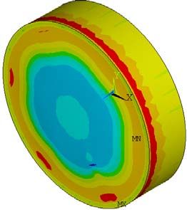
Nevertheless these results are based on simplified heating and stress calculations.
Equilibrium temperature calculations for the swept beam assumed an ideal uniform
distribution of beam power amongst the sweep circle, without taking into account that
successive bunch trains are impinging there. Static stresses due to average temperature
gradients in the dump have not been considered at all up to this point. Both topics are subject
to the following sections of this chapter.
In addition the critical question of heat transfer at the radial C / Cu boundary will be
addressed in more detail theoretically as well as practically in terms of first thoughts on its
technical realization.
21You can also read