DESIGN AND ANALYSIS OF A SLANTED CABLE-STAYED BUILDING - DIVA
←
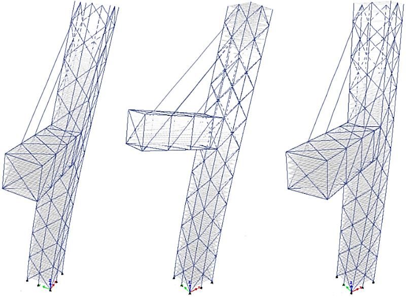
→
Page content transcription
If your browser does not render page correctly, please read the page content below
DEGREE PROJECT IN CIVIL ENGINEERING AND URBAN
MANAGEMENT,
SECOND CYCLE, 30 CREDITS
STOCKHOLM , SWEDEN 2017

Design and Analysis of a
Slanted Cable-stayed
Building
MATEA BRADARI

DAVID DESIMONS

KTH ROYAL INSTITUTE OF TECHNOLOGY
SCHOOL OF ARCHITECTURE AND THE BUILT ENVIRONMENT

Design and Analysis of a
 Slanted Cable-stayed Building
___________________________________________________________________________

 by
 Matea Bradarić and David Desimons
 KTH Royal Institute of Technology
 June 2017

___________________________________________________________________________

 Master of Science Thesis
 Stockholm, Sweden 2017
TRITA – BKN. Master Thesis 508 KTH School of ABE
ISSN 1103-4297 SE-100 44 Stockholm
ISRN KTH/BKN/EX--508--SE SWEDEN

© Matea Bradarić & David Desimons
Royal Institute of Technology (KTH)
Division of Structural Engineering and Bridges
Abstract
The Tubed Mega Frame (TMF) is a structural system for high-rise building developed by Tyréns AB.
Compared to conventional structural systems, the TMF is a coreless system that transfers the loads
through the perimeter of the building instead and in turn enables ability to support new
architectural shapes and forms of buildings. This thesis covers an initial study of a high-rise building
with an unconventional shape implementing the TMF system, the Cable-stayed Building, which
consists of a slanted tower with a cable-supported cantilever.
The study of the building was divided in to a geometrical study and a cable study. The geometrical
study was carried out to gain an initial understanding of the global structural behavior by altering
specific geometrical parameters. The cable efficiency in terms of total vertical forces was
investigated in the cable study by comparing different cable arrangements, cable diameters and
prestressing forces for a fixed global geometry. The studies were performed under linear and
nonlinear static conditions using the finite element software SAP2000 and ETABS.
The results from the geometrical study showed that the cable efficiency increases in terms of larger
vertical cable forces with a less inclined building and longer cantilever length. In addition, the results
showed significant effects of geometric nonlinearities considering P-delta for different geometric
cases. Furthermore, a study of the axial forces in the mega columns indicated that the most inclined
building in which no uplifting forces and barely any tension occur along the mega columns, is the
7° incline with cantilever length 73.4 m.
As abovementioned, the efficiency of the cables was compared for different arrangements, cable
diameter and prestressing forces. The results indicated that as the prestressing force increases, the
efficiency of cables rises more for smaller cable diameter than for larger. Furthermore, the
comparison of fan- and harp-shape cable arrangements showed that the latter, including three pairs
of cables, gives the highest cable efficiency relative to the amount of steel required of the cantilever
bracing system. Nevertheless, the study indicates that the cable forces are inherently dependent on
many parameters, such as the sag effect considered in the modulus of elasticity and the stress
inducing temperature, which in turn depends on cable diameter, prestressing force and cable
arrangement.
To conclude the study, a modal analysis showed that the Cable-stayed Building is classified as a
stiff building according to the guidelines from Council on Tall Buildings and Urban Habitat.
Further research on the structure could be carried out within different areas, as this thesis is only
an initial study of the structure. For instance, material nonlinearities, dynamic responses of the
building as well as soil structure interaction, should be investigated further.

Keywords: Tubed Mega Frame, high-rise buildings, SAP2000, ETABS, cable-stayed structures

 i
ii
Sammanfattning
Tubed Mega Frame (TMF) är ett bärande system för höghus utvecklat av Tyréns AB. TMF är, till
skillnad från nuvarande konstruktioner, ett system utan en bärande kärna som överför laster via
byggnadens perimeter istället, vilket skapar nya förutsättningar gällande arkitektoniska former på
höghus. I detta projektarbete genomförs en förstudie på en byggnad med en ovanlig design,
Snedkabel Byggnaden, bestående av ett lutande torn och en konsol som bärs upp av kablar.
Studien är uppdelad i en geometrisk analys och en kabel analys. Den geometriska studien syftar till
att få en uppfattning om hur det globala bärande systemet beter sig genom att variera vissa
geometriska parametrar. Syftet med kabel studiens är att undersöka kablarnas effektivitet genom
att jämföra den totala vertikala kabelkraften med olika kabelsystem, kabeldiametrar och
förspänningar för en fastställd geometri av byggnaden. Statiskt linjära och ickelinjära
strukturanalyser genomfördes för båda studier i finita element programmen SAP2000 och ETABS.
Resultaten från den geometriska studien visade att kabel effektiviteten ökar för en mindre lutad
byggnad och en längre konsol, då kabelkrafterna ökar. Dessutom indikerar resultaten
anmärkningsvärda effekter vid beaktandet av ickelinjäritet med P-delta för olika globala geometrier.
En undersökning av axialkrafter i pelarna visar att den mest lutade byggnaden som inte ger upphov
till upplyftande krafter och knappt några dragkrafter längs pelarna är byggnaden med 7° lutning
och konsollängd på 73.4 m.
Som tidigare nämnt undersöktes kablarna effektivitet genom att jämföra olika kabelsystem,
kabeldiametrar och förspänningar. Resultaten påvisade att med högre förspänningar, desto mer
ökar kabeleffektiviteten för mindre kabeldiameter än större. Dessutom visade jämförelsen mellan
solfjäder- och harp-systemet att harp-systemet med tre kabelpar ger stört kabeleffektivitet i relation till
stålmassan för stagningen i konsolen. Krafterna i kablarna beror i sig till stor del av exempelvis
elasticitets modulen med hänsyn till kablarnas nedböjning och den spänningsinducerande
temperaturen, som i sin tur beror på kabeldiameter, förspänning och kabelsystem.
Avslutningsvis utfördes en modalanalys som visade på att Snedkabel Byggnaden klassificeras som
en styv byggnad enligt riktlinjer från Council on Tall Buildings and Urban Habitat.
Ytterligare studier på strukturen kan genomföras inom olika områden, då detta är en förstudie på
byggnaden. Exempelvis på vidare forskning är att ta hänsyn till materialens ickelinjäriteter,
byggnadens dynamiska respons samt samverkan mellan byggnad och grund.

Nyckelord: Tubed Mega Frame, höghus, SAP2000, ETABS, snedkabelstrukturer

 iii
iv
Preface
It has been a pleasant and educative time writing this master thesis initiated by the engineering firm
Tyréns AB. This thesis has been written at the Division of Structural Engineering and Bridges at the Royal
Institute of Technology (KTH) in Stockholm, and concludes hereby a five-year civil engineering degree.
We want to give a special thanks to our supervisor Fritz King at Tyréns for helping and supporting
us during the study of this thesis. His great knowledge about the topic and cheerful mind has truly
guided us throughout the process of this project.
In addition, we would like to express our appreciation for the bridge department at Tyréns for
allowing us to carry out the thesis at their office and the friendly welcome from the employees.
We want to thank our examiner Raid Karoumi for inspiring us throughout our master studies at
KTH and for growing our interest within the area of structural engineering.

Finally yet importantly, the support from our families, as well as from our fellow graduate students,
has meant tremendously to us during these five years of civil engineering studies. Thank you!

Matea Bradaric David Desimons

Stockholm, June, 2017 Stockholm, June, 2017

Supervisor Tyréns AB: Fritz King

Supervisor KTH: Raid Karoumi

Examiner KTH: Raid Karoumi

 v
vi
List of notations

A Cross-section area

a Horizontal length of cable
α Coefficient of thermal expansion

B Width of the face in x-direction
B Width of the face in y-direction

C External pressure coefficient

[d] Vector of node displacements

∆   Deflection

E Modulus of elasticity

E Equivalent modulus of elasticity

E Tangent modulus
E Secant modulus

e Eccentricity in x-direction
e Eccentricity in y-direction

ε Elastic strain

ε Thermal strain

f   Vertical cable deflection

[F] Vector of node forces

ϕ Inclination of the cable
G Gust effect factor

GC Internal pressure coefficient

γ Weight of the cable
I Second moment of inertia

[K] Stiffness matrix

L Length

 vii
M Moment

M Torsional moment
p Wind pressure

P Leeward face resulting force in x-direction
P Leeward face resulting force in y-direction
P Windward face resulting force in x-direction
P Windward face resulting force in y-direction
q Wind pressure qz for windward walls evaluated at height z above the ground

q Wind pressure qh for leeward walls, side walls, and roofs, evaluated at height h

q Wind pressure qh for windward walls, side walls, leeward walls, and roofs of
 enclosed buildings and for negative internal pressure evaluation in partially
 enclosed buildings

S Cable force
ΔS Mean cable force
Δs Total elongation of cable
σ Cable stress

T Cable tension force
ΔT Mean cable tension
∆T Stress inducing temperature

V Shear force

 viii
Table of Contents
1. Introduction ....................................................................................................................... 1
 1.1 Background ......................................................................................................................................................... 1
 1.2 Purpose and aim ................................................................................................................................................. 2
 1.3 Method ................................................................................................................................................................. 3
 1.3.1 Literature study ........................................................................................................................................... 3
 1.3.2 Geometrical study ....................................................................................................................................... 3
 1.3.3 Cable study................................................................................................................................................... 4
 1.4 Limitations ........................................................................................................................................................... 4

2. Tall Buildings .................................................................................................................... 5
 2.1 Background ......................................................................................................................................................... 5
 2.1.1 Definition ..................................................................................................................................................... 5
 2.2 Structural systems in tall buildings ................................................................................................................... 6
 2.2.1 Structural systems in slanted buildings .................................................................................................... 7
 2.4 The Tubed Mega Frame .................................................................................................................................... 9
 2.5 The MULTI Elevator system .........................................................................................................................10

3. Cable-supported structures ............................................................................................. 11
 3.1 Introduction ......................................................................................................................................................11
 3.1.1 Existing cable-supported structures ......................................................................................................11
 3.2 Wires and cable-strands ...................................................................................................................................12
 3.2.1 Seven-wire strand......................................................................................................................................13
 3.2.2 Multi-wire helical strands.........................................................................................................................13
 3.2.3 Locked-coil strands ..................................................................................................................................14
 3.2.4 Parallel-wire strands and its improvement............................................................................................14
 3.3 Behavior of the single cable element .............................................................................................................15
 3.4 Equivalent modulus of elasticity ....................................................................................................................16

4. Structural mechanics and wind loads ............................................................................. 19
 4.1 P-Delta effect ....................................................................................................................................................19
 4.2 Wind load...........................................................................................................................................................20
 4.2.1 Vortex shedding ........................................................................................................................................23

5. Finite element modelling ................................................................................................ 25
 5.1 Introduction ......................................................................................................................................................25

 ix
5.2 ETABS and SAP2000 ......................................................................................................................................26
 5.3 Modelling approach .........................................................................................................................................26
 5.3.1 Shell elements ............................................................................................................................................26
 5.3.2 Diaphragm constraints.............................................................................................................................28
 5.3.3 Frame elements .........................................................................................................................................29
 5.3.4 Modelling of cables ..................................................................................................................................29
 5.3.5 P-delta in SAP2000 and ETABS ............................................................................................................30

6. Geometrical study ........................................................................................................... 31
 6.1 Introduction ......................................................................................................................................................31
 6.2 Slenderness ratio ...............................................................................................................................................31
 6.3 Load input .........................................................................................................................................................32
 6.4 The geometrical study ......................................................................................................................................33
 6.4.1 Cantilever length depending on inclination of the building ..............................................................33
 6.4.2. Simplified model including cables.........................................................................................................35
 6.4.3 Vertical cable force in Case 3 compared to reaction force in Case 2 ...............................................40
 6.4.4 Axial forces in the mega columns ..........................................................................................................41
 6.4.5 The P-delta effects on the building........................................................................................................45
 6.5 Discussion and conclusion of the geometrical study..................................................................................47

7. Cable study ...................................................................................................................... 49
 7.1 Introduction ......................................................................................................................................................49
 7.2 The finite element model ................................................................................................................................51
 7.2.1 Dimensions ................................................................................................................................................51
 7.2.2 Material properties ....................................................................................................................................51
 7.2.3 Applied loads .............................................................................................................................................51
 7.2.4 Modelling approach ..................................................................................................................................52
 7.3 The cable study .................................................................................................................................................52
 7.3.1 Model verification .....................................................................................................................................52
 7.3.2 Cable frame element size .........................................................................................................................52
 7.3.3 Cable forces depending on diameter and prestressing force .............................................................53
 7.3.4 Steel frame design check of the cantilever ............................................................................................56
 7.3.5 Modal analysis ...........................................................................................................................................57

8. Discussion, conclusion and proposed further studies .................................................... 61
 8.1 Discussion and conclusion ............................................................................................................ 61
 8.2 Proposed further studies ............................................................................................................... 62

9. References ....................................................................................................................... 63

Appendix A: Bending moments for the simplified stick- model ....................................... 67

 x
Appendix B: The Gust Effect factor according to ASCE 7 -10 ........................................... 69
Appendix C: Hand calculation of the mass ........................................................................ 73
Appendix D: Equivalent modulus of elasticity................................................................... 79
Appendix E: The first three global mode shapes of the building ...................................... 81

 xi
xii
Chapter 1
Introduction

1.1 Background
With an increased population growth and a rapid development of communities, high-rise buildings
have become a symbol of urbanization, social development and economic prosperity in cities
around the world (Sha et al., 2014). With new inventions in elevator technology, in conjunction
with greater knowledge in structural engineering and improved design codes, the structural system
of high-rise buildings has advanced in such a way that skyscrapers are built higher and slender than
ever before. To give an idea of the current progress, Jeddah Tower in Saudi Arabia is expected to
reach the unprecedented one kilometer threshold after completed construction in year 2020 (The
Skyscraper Center, 2017). Another remarkable work in progress is the 111 West 57th Street in New
York, which will become the slenderest building with a width-to-height ratio of 1:23 after
completed construction in year 2018, see Figure 1.1 (Willis, 2015). Thus, from the increased
demands in growing cities together with more structural advanced and effective buildings, the
number of high-rise buildings has tripled over the past 30 years (King et al., 2012).
Many of today’s existing high-rise buildings have a structural system that consists of a service
central core tied together with the perimeter of the building. The core usually holds concrete
elevator shafts and acts as the main loadbearing element of the building. Due to the interaction
between the core combined with other structural elements, the high-rise building is provided with
a structural lateral stiffness against dynamic loading (Choi et al., 2012). However, implementing a
structural system including a central core reduces the floor area utilization as the elevator shafts
occupies a large amount of space when the building gets higher. Besides the floor utilization
drawback, a structural system with a central core has its restrictions for different shapes and forms
of tall buildings. Since the core allows vertical transportation systems only, most of the existing tall
buildings are repetitiously standing straight up. Hence, building high-rise buildings with the central
core might not be the most effective structural system when aiming for future innovative solutions.
The Swedish engineering firm Tyréns AB has developed a structural system, which implies to
eliminate the central core in high-rise buildings. The structural system is called the Tubed Mega Frame
(TMF) and it functions by transferring the loads through the perimeter of the building instead. Due
to the coreless system, the TMF system increases the floor utilization as well as its ability to support
new architectural shapes and forms (King et al., 2012). For example, slanting a high-rise building
with the TMF system can reach remarkable inclinations while retaining a high slenderness ratio.
Even though the TMF has not yet been applied, the structural system serves nevertheless an
innovative future for high-rise buildings.

 1
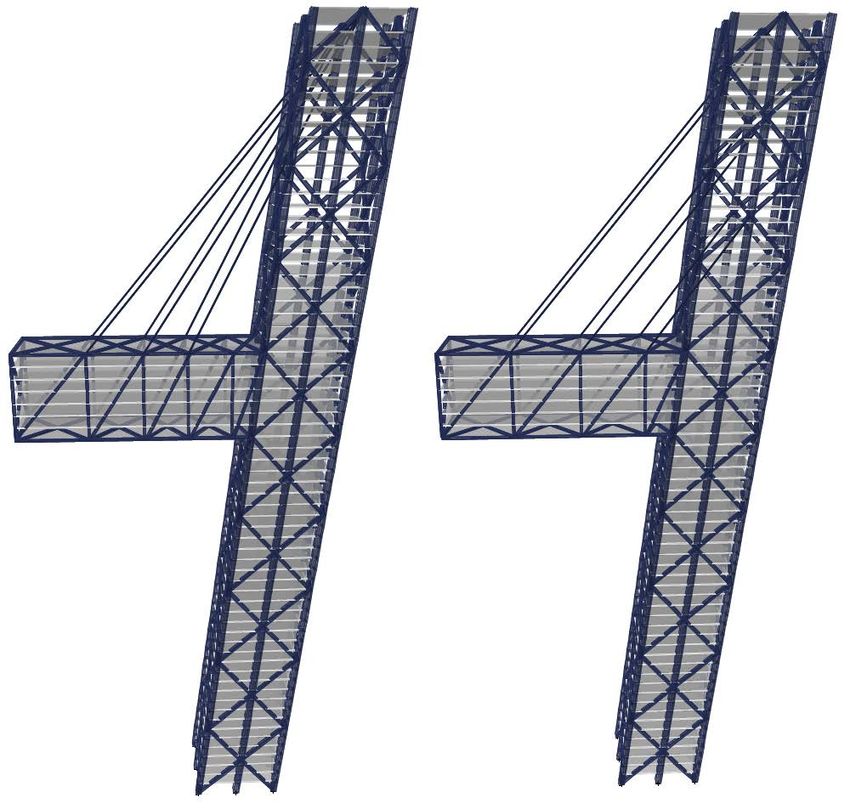
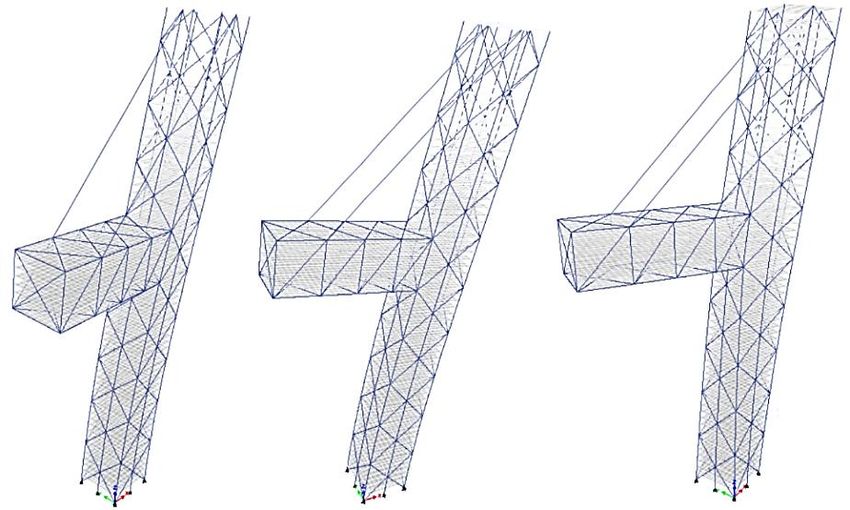
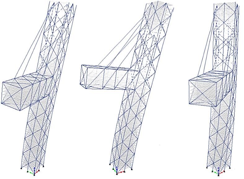
Chapter 1. Introduction

Figure 1.1 Buildings under construction: the Jeddah Tower to the left (The Skyscraper Center, 2017) and the
 111 West 57th Street to the right (Willis, 2015).

1.2 Purpose and aim
The purpose of this thesis is to carry out an initial study on a high-rise building with a new
unconventional shape enabled by the Tubed Mega Frame concept. The shape is inspired by a
combination of a tall building and a cable-stayed bridge, hence the name Cable-stayed Building, see
Figure 1.2. The building is slanted with a height of 257 m and has a slenderness ratio of 1:9.4.
The thesis is divided into two parts, a geometrical study and a cable study. The geometrical study
treats the building as a simplified two-dimensional model and a three-dimensional model, in order
to give an initial understanding of the structural behavior of the building with and without cables.
The aim is to investigate the effects of varying geometrical and modelling parameters under linear
and nonlinear static conditions on the structure.
The cable study aims to investigate the efficiency of the cables depending on varying cable
arrangements on the building, cable diameters and prestressing forces under nonlinear static
conditions for a three-dimensional model of the building. The efficiency of the cables is defined
by estimating the total vertical cable force in relation to the cantilever weight. A comparison of the
different cases and parameters indicates if any remarkable deviation in cable efficiency occur
between them.

 2
1.3 Method

Figure 1.2 Initial sketch of the Cable-stayed Building. The structure consists of a slanted high-rise building with a
 cable-supported, liveable cantilever.

1.3 Method

1.3.1 Literature study
Firstly, a literature study was carried out focusing on conventional high-rise buildings and the TMF
concept in order to gain information about different structural systems. Since the prototype
building is slanted, the study of conventional high-rise buildings will also include current structural
systems in some of today’s existing slanted buildings.
Besides the structural systems in high-rise buildings, a part of the literature study covers different
types of cables and cable-supported structures. Furthermore, the nonlinear behavior of cable is
briefly described, which is then applied to the finite element modelling approach of the prototype
building.
Since the analysis of the building is performed using the codes ASCE 7-10 (American Society of Civil
Engineers) for wind loads and AISC 360-10 (American Institute of Steel Construction) for design of steel
sections, the wind load calculations and design load combinations are presented.

1.3.2 Geometrical study
The geometrical study was carried out using the software SAP2000 for the simplified two-
dimensional model and ETABS for the three-dimensional model under linear and nonlinear static
conditions considering dead and wind load. Live loads were applied to the structure for the
nonlinear P-delta analysis. The coefficients used for the wind load are based on a previous study
of TMF high-rise buildings by Zhang (2014) using the ASCE 7-10. However, the parameters
dependent on the specific geometry of the building should be calculated separately, which has been
done for the studied prototype building, see Appendix B.

A simplified two-dimensional model was analyzed in order to gain an initial understanding of the
global behavior of the building. This was carried out by altering geometrical parameters such as
inclination and length of cantilever. In this case, the simplified model should correspond to the
three-dimensional model in terms of stiffness. This approach decreases the amount of models to

 3
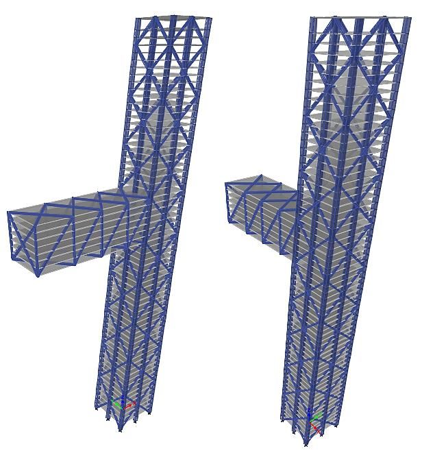
Chapter 1. Introduction

run and computational time. Nevertheless, a two-dimensional model of the building can be useful
for preliminary design stage, but a three-dimensional model is required for a more adequate analysis
regarding interaction between the columns, bracings and slabs in the building.

1.3.3 Cable study
A non-linear static analysis of the building is performed in ETABS in order to estimate the cable
efficiency. In this study, the cables were modelled using straight frame elements. Since ETABS is
a special purpose software developed for multi-story buildings, modelling cables is limited to frame
elements. However, in order to capture an adequate behavior of the cable, nonlinear properties can
be assigned to the frame element. For instance, the initial sagging of a cable can be considered by
assigning an equivalent modulus of elasticity to the cable material. The equivalent modulus of
elasticity used in this analysis is based on the tangent modulus method, which is derived from a
parabola shaped assumption of the cable deflection. This method is sufficient when modelling
cables in general and the errors are relatively small compared with a catenary shaped assumption
of the deflection (Sundquist, 2010).

Furthermore, a decision was made on whether to model the cables as single frame elements or
dividing the frame into numerous elements. Since results from a convergence analysis indicates
that a division of the frame does not give a remarkable influence on the cable behavior in terms of
global modes, the study was carried out by assigning a single frame element to each cable.

1.4 Limitations
Since this thesis treats an initial study of a new prototype building, the study will only focus on the
super structure of the building, which is the main load bearing components. The super structure
includes mega columns, slabs and bracing system, and excludes for instance internal columns or
walls. Additionally, the study is limited for a fixed height of the building and placement of the
cantilever. In the thesis, only the inclination of the building, length of the cantilever and number
of cables attached are altered in terms of the appearance of the building.
The study is limited for only dead load and wind load, however, vortex shedding due to wind
actions is neglected. Live load is applied when analyzing the effects of P-delta only. Other loads,
for instance loads from façade and installation, are neglected.
The analyses carried out in this thesis is limited to linear and nonlinear static conditions. Material
nonlinearity is neglected such as creep, cracking and shrinkage in concrete.
Finally, since the site of the prototype building is not specified, the soil conditions are not
considered or modeled in the analysis. The mega columns are assigned pinned boundary conditions
at the base, which simulates the bending and rotation of the columns and building itself.

 4
Chapter 2
Tall Buildings
2.1 Background
During the 19th century, the development of tall buildings started off by constructing buildings with
outer masonry walls as the main load bearing structure (Partovi and Svärd, 2016). This structural
system was found to be inconvenient because as the number of stories increased, so did the
thickness of the masonry walls at the bottom. Thus, a large base area was required to build multiple
story buildings (usually around 5 stories) which partly led to expensive costs. With the invention
of elevators, a new structural system was developed using steel grids and columns to resist stresses
and forces arising in the structure, allowing the buildings to grow in height.
The first building to be called the world's first tall building was the Equitable Life Assurance Building
in New York (Ho, 2016). It was completed 1870 and with its 40 meters, it was also the first building
incorporating passenger elevators. However, the term tall building is not precisely defined, but one
of the claims for a building to be called a tall building according to the standard is that some kind
of technology (such as a transportation system) should be included. Moreover, the definition of
tall building is clarified later in this chapter. From the 19th century until the past decades, the factors
such as advanced elevator technologies and efficient structural systems for high-rise buildings have
paved the way for a new era of so called skyscrapers.
The expansion of high-rise buildings around the world has not only arisen from ever-denser cities
or to increase the commercial return on a development by investing on tall buildings (Wood and
Oldfield, 2008). The vitality of a city is projected by the architecture of tall buildings and skylines
with international brand recognition. Nevertheless, the future trends in high-rise buildings are
predicted to strive for sustainability in terms of integration with new technologies, design and
operations (Zhang, 2014).

2.1.1 Definition
According to the Council on Tall Buildings and Urban Habitat (CTBUH), there is no absolute definition
of what the characterization tall building constitutes. A tall building is not just about height, but
rather a building that exhibits elements of tallness in one or more of the following three categories:

 a. Height relative to context – A building with a certain height might not be considered a
 tall building in a high-rise city like Hong Kong and Chicago, but in a European suburb, it
 may be perceived as a tall building, see Figure 2.1 a).

 b. Proportion – There are buildings that are not particularly high but have a slenderness ratio
 enough to give the look of a tall building. On the other hand, there are buildings that are

 5
Chapter 2. Tall Buildings

 high but because of their large base/floor area, they are not giving the appearance of a tall
 building, see Figure 2.1 b).

 c. Tall building technologies – A building can be classified as tall building if it contains
 technologies such as specific elevator technologies and structural wind bracing as a product
 of height. The technologies may have an attribution as being a product of tall.

Figure 2.1 Figure a) illustrates how the height of a building is perceived differently depending on the context, and b)
 illustrates how a building is giving the appearance of tall building depending on the proportions
 (CTBUH, 2016.b).

To account the number of floors in a building as an indication of a tall building is not sufficient
due to the change of variation of floor-to-floor height between different buildings. However,
CTBUH defines a building as super-tall if it exceeds 300 meters in height, and mega-tall if it exceeds
600 meters.
The same principle of measuring height of a straight building applies for slanted buildings, meaning
that the height is measure vertically from the base the top.

2.2 Structural systems in tall buildings
A high-rise building is mainly subjected to gravity loads and lateral loads caused by wind and seismic
actions. Since a high-rise building acts characteristically like a freestanding cantilever, the horizontal
lateral loads on the structure become severe as the height of the building increases. Hence, the
horizontal stiffness of the structural system in a high-rise building is important in order to provide
resistance to the loads.
The main purpose of the structural system in a high-rise building is to transfer the loads through
other structural components, connected in an efficient manner (Rana and Rana, 2014). There are
several basic forms of structural systems, which can be combined to achieve the desirable
performance, see Figure 2.2. For example, in the early 20th century, high-rise buildings were mostly
constructed with a moment frame system using reinforced concrete (Zhang, 2014). A moment frame
consists of rigidly connected columns and beams, which provides the advantage of reducing
bending moment and buckling length of columns. However, the low stiffness of a moment frame
system produces large displacements when subjected to lateral loads, hence limiting the height of
buildings. In interest of building higher, the structural systems with cast-on-site concrete shear walls
was developed and consequently allowed the buildings to become even higher as the walls provided
sufficient lateral stiffness.

 6
2.2 Structural systems in tall buildings

Figure 2.2 Various structural systems for different number of stories and heights (Rana and Rana, 2014).

Despite the stiffness provided by the shear wall system, the structural plan was not as flexible as
desired. Therefore, a combination of the moment frame and shear walls was introduced, the frame-
shear wall system (Zhang, 2014). With a proper number of shear walls placed in the moment frame,
the structural system achieves enough horizontal stiffness while retaining a flexible structural plan.
This made the frame-shear wall system applicable in a wide range of buildings as well as heights.
Nevertheless, along the growth of cities and the striving to build even higher structures, the central
core system was invented. It has been widely used for constructing high-rise buildings because of its
resistance to horizontal and vertical loads (Partovi and Svärd, 2016). The core is usually combined
with other basic structural systems. As an example, the tube in tube system incorporates the core
combined with an external frame tube with columns and beams. Another example of combining the
core is the trussed tube system that has an outer bracing system consisting of diagonals attached to
the corners. This system is more efficient than a moment frame since the diagonal bracing has a
large effect on the lateral stability of the structure (Partovi and Svärd, 2016).
Besides the various structural systems, the construction materials utilized is reinforced concrete for
the core and perimeter columns, whereas outriggers and bracing system consist mainly of steel
(Zhang, 2014). Furthermore, the development of composite materials as construction material is
an important subject when aiming for very high buildings because of the advantageous properties
of steel and concrete.

2.2.1 Structural systems in slanted buildings
Among the repetitiously straight shaped buildings, some existing high-rise buildings deviate from
the standard shape. Two of them is the world's first inclined skyscrapers, the twin office buildings
Puerta de Europa Torre I and II, both constructed year 1996 in Madrid (Winstanley, 2011). The
purpose of the design of the buildings was to break the linear design concept. Figure 2.3 shows one
of the two buildings, Puerta de Europa Torre I. Each building reaches a height of 113.8 meters
with an inclination of 15° (Winstanley, 2011). The structural solution to counteract the overturning
forces of the towers includes a 60 x 10 x 10 meter concrete counterweight located at the opposite
side of inclination underground connected to the top by cable. A concrete core strengthens further,
 7
Chapter 2. Tall Buildings

together with a primary steel diagrid on the perimeter. Secondary vertical and horizontal steel
members, which can be seen on the façade, strengthens the diagrid and provides a lateral stability.

Figure 2.3 A picture of the Puerta de Europa Torre I and a section of the building (Winstanley, 2011).

The twin towers of Puerta de Europa have undoubtedly served an iconic inspiration for the
following decades. Today, the building that has the title of the world's furthest leaning building is
the Capital Gate Tower, see Figure 2.4 (CTBUH, 2012). With its 165 meters, the tower has an 18°
westward lean. The structural system consists of a concrete core that occupies the only vertical
space available in the profile. Steel beams span in between the core and the surrounding external
steel diagrid that forms the tower (Schofield, 2012). During construction, a pre-cambered core was
erected with a slightly off vertical position, which eventually straightened up the tower when the
floors were added in the opposite side. Hence, the Capital Gate Tower was the first building in the
world to use a pre-cambered core with a built in lean (Schofield, 2012). Besides the impressive
structural concept, the architectural design of the building aims to serve as a signature tower to
reflect the dynamism of the city and to celebrate the human achievement.

 8
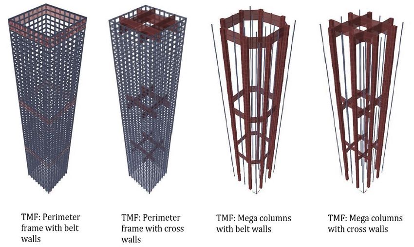
2.4 The Tubed Mega Frame

Figure 2.4 The Capital Gate Tower in Abu Dhabi and a section of the building (Schofield, 2012).

2.4 The Tubed Mega Frame
As mentioned before, the Tubed Mega Frame concept is a new and innovative structural system
under development for high-rise buildings. The main concept of the TMF is to eliminate the core
and instead allow the loads to be transferred through the perimeter of the building. There are
different types of TMF and four of them are shown in Figure 2.5. The TMF implies either mega
columns or a frame system composing the perimeter of a building. The mega columns and the
frame system can be combined with other structural elements such as belt walls, cross walls or
other bracing systems. Moreover, the previous study by Partovi and Svärd (2016) has shown that the
TMF is more structural efficient than the core system in terms of deformations and eigenmodes
with increased height of the building.
Among the benefits of the TMF, such as effective floor utilization and possibilities for new design
shapes, there is potential of new transportation technologies to breakthrough in the world of
skyscrapers. With the TMF system, a building is not restricted to utilize conventional rope-
dependent elevators that move through massive concrete shafts. Thus, the innovative aspect of the
TMF concept covers more than the structural system itself.

 9
Chapter 2. Tall Buildings

Figure 2.5 Different types of the TMF system (Partovi and Svärd, 2016).

2.5 The MULTI Elevator system
An innovative solution for transporting people in tall and various shaped building is the MULTI
elevator system developed by ThyssenKrupp AG. The MULTI is the world's first rope-free elevator
based on a linear motor technology that allows vertical, horizontal and diagonal transportation in
the building (ThyssenKrupp, 2015). The drawback with the conventional passenger elevators is the
requirement of added shafts as the height increases of a tall building. Thus, the ineffectiveness of
floor utilization becomes remarkable. Besides the waste of floor space, standard elevators also limit
the functionality, shape and design of high-rise buildings. Therefore, innovative solutions for
transporting people efficiently in future buildings is a necessity.
With the flexibility of the MULTI elevator system, the technology can be incorporated in the
studied Cable-stayed Building. Since the building is slanted as well as slender, a conventional
elevator system with shafts would not fit inside the building, as it is not designed with a core system.
Therefore, an elevator technology equal to the MULTI elevator system is suitable for the building
as passengers can move in different directions than vertically straight.

 10
Chapter 3
Cable-supported structures

3.1 Introduction
Cable-supported structures have been used by humankind from time immemorial. One of the
oldest examples on cable-supported structure are the liana bridges, which were used to cross rivers
and ravines. The principle of cable-supported structures is based on utilizing pure tension by using
the tensile strength of the cable material optimally. No or negligible flexural forces will arise because
the bearing cables adapt their geometrical shape to the acting load. As the tensile strength is utilised
across the whole cross-section, slender framework as well as a lower weight allows building longer
spans. Cables are typically applied as bearing systems for cranes, bridges with longer spans than
200 m, roof bearing systems in sports arenas and exhibition halls etc. (Sundquist, 2010)

3.1.1 Existing cable-supported structures
Two of existing cable-supported structure that remind of the Cable-stayed Building are the Montreal
Olympic Stadium Tower and Puente del Alamillo, in such way they consist of a inclined tower and
supporting cables.
The Montreal Olympic Stadium Tower is the highest leaning tower in the world since 1987 when
the construction was completed with the height of 165 m (Guinness World Record, 2017), see
Figure 3.1. Due to the mass ratio where the base of the tower has a mass of 145 000 tons while the
top has a mass of 8 000 tons, the tower is enabled to slant at an angle of 45° (Parc Olympique, n.d).
The tower supports the retractable roof with 26 cables and 17 edge cables that are anchored at the
concrete roof, which contains 34 cantilevers that supports the technical ring where the edge cables
are anchored. All the cables are the type of fully locked coil cables (SBP, n.d).

Figure 3.1 The Montreal Tower supports the arena roof with cables (Flickr, n.d).

 11
Chapter 3. Cable-supported structures

Puente del Alamillo is a cable-stayed road and pedestrian bridge built in 1992. The inclined pylon
is 134 m high with an inclination of 58° and is the first bridge in the world that is not back-
anchored, see Figure 3.2. The bridge span is 200 m long between the supports and 13 pair of steel
cables transfer the loads to the pylon. The cables consist of 60 strands each with a 15mm diameter,
except for the longest cable that consists of 45 strands (Wikiarquitectura, 2017). Hence, the total
cable diameter is roughly 120 mm while the longest cables have a diameter of 100 mm. The idea
behind the design is that resultant force along the pylon axis, created by weight of the pylon and
the main span forces transmitted by the cables, balances with the deck axial force to produce a
vertical resultant reaction. Because of the force balance, the pylon is not required to be back-
anchored. (Guest et al, 2013)

Figure 3.2 A drawing of the Puente del Alamillo, Spain (Guest et al, 2013).

3.2 Wires and cable-strands
The single steel wire forms the basic element for the modern cables. The main cable consist either
of a single strand or a bundle of several strands (Sundquist, 2010). Steel wires are often cylindrically
shaped with a diameter of approximately 5 mm for the main cable in suspension bridges, while for
cable stayed bridges up to 7 mm. The steel material used in the wires are made of high-strength,
cold-worked steel and is characterized by its content of carbon, which is higher than the allowed
content for structural steel. Due to the high content of carbon in cable steel, it is unsuited for
welding in comparison to structural steel. It is regarded mandatory today to use galvanized wires
for better resistance against corrosion. Despite the strength of the cable is approximately twice as
large as high-strength structural steel, the ductility of cable steel is decreased as the strain at breaking
is one sixth of structural steel. Table 3.1 shows a comparison of cable steel and structural steel.
(Gimsing and Georgakis, 2012)

 12
3.2 Wires and cable-strands

Table 3.1 Comparison of conventional cable steel and structural steel (Gimsing and Georgakis, 2012).

 Conventional cable steel Structural steel

 Unity (5 or 7 mm wires) Mild High strength
 Yield stress ( = 2% proof stress) MPa 1180 240 690
 Tensile strength MPa 1570 370 790
 Strain at breaking % 4 24
 Modulus of elasticity GPa 205 210 210

3.2.1 Seven-wire strand
The simplest strand for cable-supported structures is the seven-wire strand, see Figure 3.3, which is
mostly used in tendons for prestressed concrete. The diameter of a seven-wire strand is 15 mm.
The wires in the seven-wire strand have the tensile strength in the range of 1770 and 1860 MPa
and the modulus of elasticity for the seven-wire strand is 190 GPa. (Gimsing and Georgakis, 2012)

Figure 3.3 Seven-wire strand (Gimsing and Georgakis, 2012).

3.2.2 Multi-wire helical strands
The multi-wire helical strand consists of a straight circular core with several layers of wires which are
directed opposite of helix, see Figure 3.4. The helical strands become self-compacting due to the
twisting and hence no wrapping around the strand is needed to hold the wires together. Because
of the twisting, the decrease of the stiffness is further noticeable than for the seven-wire strand,
giving the helical strand a modulus of elasticity of 170 GPa (Sundquist, 2010). Plastic deformation
occurs when the strand is subjected to axial tension for the first time, which decreases the modulus
of elasticity even more. Thus, it is necessary to prestress the strand with a force exceeding the
maximum tensile force of 10-20 %. (Gimsing and Georgakis, 2012)

Figure 3.4 Multi-wire helical strand used in Lilleaelt Bridge (Gimsing & Georgakis, 2012).

 13
Chapter 3. Cable-supported structures

3.2.3 Locked-coil strands
Locked-coil strands entails a core that holds wires with circular cross-sections, similar to the helical
strand. The difference is that the central core is not only surrounded by circular wires but also by
layers of wires with a Z-profile and the wires are chosen so their spiral twists interlock with each
other, see Figure 3.5. The interlocking and the self-compacting ensures of a tighter surface for the
cable and a small void ratio inside the strand. Therefore, the locked-coil strand is the most compact
strand of them all. A good corrosion resistance is obtained and therefore only paint is necessary to
cover the strand. The strength of the wires used in the locked-coil strand is in the range of 1370-
1570 MPa. Locked-coil strands are pre-fabricated and delivered in full length to site, diameters of
the strands can vary from 40-180 mm. The modulus of elasticity for locked-coil strands is 180 GPa
which is higher than for helical strands. (Gimsing and Georgakis, 2012)

Figure 3.5 Cross-section of a locked-coil strand (Gimsing and Georgakis, 2012).

3.2.4 Parallel-wire strands and its improvement
Parallel-wire strand (PWS) is composed by many straight wires, see Figure 3.6i, which are kept in place
by twisting a steel rope around. An improvement of the PWS is made by wrapping the wires with
a cover to simplify reeling and unreeling, but also self-compaction due to axial tension. The outer
layer of high density polyethylene (HDPE) eliminates voids between the wires and the surrounding
pipe, see Figure 3.6ii. Figure 3.6iii shows an alternative type, the parallel seven-wire strand, where each
wire is composed by an individual seven-wire strand. The modulus of elasticity for the parallel
seven-wire strand cables are 190 GPa and the design tensile stress is 800 MPa. (Gimsing and
Georgakis, 2012)

Figure 3.6 Sections of i) Parallel-wire strand, ii) The improved PWS and iii) Parallel seven-wire strand
 (Gimsing and Georgakis, 2012).

 14
3.3 Behavior of the single cable element

3.3 Behavior of the single cable element
To get a full understanding of the behavior of cable-supported structures, it is vital to know how
the single cable responds to different loadings. A single cable carries either an axial load or a
transverse load. When a cable carries an axial load, for instance, the diagonal cable in cable-stayed
bridges, the behavior could be compared to the tensioned diagonal in a truss, see Figure 3.7. When
a cable carries a transverse load, for example, the main cable in a suspension bridge, the behavior
could be compared with a beam, see Figure 3.7.

Figure 3.7 Cable elements compared to beam elements (Gimsing and Georgakis, 2012).

A difference in the comparison of a beam or a cable carrying transverse load is the supporting
conditions. A horizontal beam loaded vertically requires only vertical supports at the ends, but for
the equivalent cable, support in vertical and horizontal direction is required at the ends, see Figure
3.8. The horizontal reaction is considerably larger compared to the vertical force in most cases.
(Gimsing and Georgakis, 2012)

Figure 3.8 Reactions at the supports for a beam and a cable (Gimsing and Georgakis, 2012).

The geometrical shape is significant for cables carrying transverse loads due to the axial force at
mid-span being inversely proportional to the sag. Hence, a straight cable is unable to carry
transverse load because zero sag means an infinitely large cable force. However, the only case to
obtain no sagging is to use a vertical cable. Thus, an inclined cable will result in a sag due to its own
deadweight. The sag is proportional to the density of the material and inversely proportional to the
strength. Hence, to assure a small sag the cable material should have a large strength in relation to
density. (Gimsing and Georgakis, 2012)

The primary task of the cable is to take up the vertical forces, and the total force is distributed
among the cables. The moments at the stiffening beam evens out more with increased amount of

 15
Chapter 3. Cable-supported structures

cables. If the number of cables are dense in a structure, i.e. a small distance between them, the
cable is often built up by one prefabricated cable. If the number of cables are less dense in a
structure, each cable is built by a numerous of prefabricated cables due to the requirement of large
cable cross-section. (Sundquist, 2010)

3.4 Equivalent modulus of elasticity
Among the complexities of modelling cables is the nonlinear behavior considering the cable shape
and sag. It becomes more complicated if the finite element software is based on elastic behavior
for each member. However, the linearization of the force/elongation relation of the cable can be
simplified by replacing the cable curve with a tangent, giving an equivalent modulus of elasticity
that accounts for the sag at the point that corresponds to the initial dead load condition (Daniell
and Macdonald, 2006), see Figure 3.9i. The equivalent modulus of elasticity is derived from a
parabola shaped assumption of the cable deflection. Nevertheless, the linearization based on the
tangent modulus can lead to intolerable deviations from the real behavior. The results deviate at
larger stress variations by either overestimating or underestimating the flexibility of cables
depending if the tension in the cables is increasing or decreasing. (Gimsing and Georgakis, 2012)

The secant modulus is another approach that can be used if the linearization with the tangent
modulus is not sufficient. The linearization using secant modulus means that the cable curve
between point A (initial dead load stress ) and B (dead and live load stress ) will be replaced
with a secant instead of a tangent, see Figure 3.9ii. The secant modulus contributes adequate cable
elongation, giving no errors in calculation in relation to the parabola shaped assumption. However,
the calculations with the secant modulus becomes more complicated than the tangent modulus.
(Gimsing and Georgakis, 2012)

Figure 3.9 i) The tangent modulus for cable stiffness, and ii) the secant modulus for cable stiffness
 (Gimsing and Georgakis, 2012).

Below, the equivalent modulus of elasticity using the tangent and secant-modulus is derived based
on Sundquist (2010) and modified according to Figure 3.10.

 16
3.4 Equivalent modulus of elasticity

Figure 3.10 The behavior of a cable during an axial load.

In general, the length of a cable can be calculated as

 dy a 8 f
 L= 1+ dx ≈ 1+ ∙ a (3.1)
 dx cos ϕ 3
 cos ϕ
and the cable force as
 T dy
 S(x) = =T∙ 1+ (3.2)
 cos ϕ dx

The elastic strain at an arbitrary point in the cable is
 2
 ΔS(x) ΔT dy
 ε(x) = = 1+ (3.3)
 EA EA dx

The total elongation is a result of an increase in the tensioning force

 δS T dy T dy
 Δs = ε(x) ∙ dx = ∙ 1+ dx − ∙ 1+ dx (3.4)
 δx EA dx EA dx

The total cable elongation is then equal to the change in cable length given in Eq. (3.1). Note that
the exact value is not used due to the terms of (dy/dx)2 because they are small if the change in the
shape adopted by the cable is small, giving the following
 T −T
 L −L ≈ (3.5)
 EA

With the approximated values for the cable length in Eq. (3.1), where L = L − L , the following
equation is obtained

 17
Chapter 3. Cable-supported structures

 a
 a Δ 8 f a 8 f (T − T ) ∙
 cos ϕ
 + 1+ ∙ a − ∙ 1+ a = (3.6)
 cos ϕ cos ϕ 3 cos ϕ 3 EA
 cos ϕ cos ϕ

Eq. (3.6) can be rearranged and by eliminating small terms, the equation becomes
 a
 Δ a 8 f f (T − T ) ∙
 cos ϕ
 = ∙ a − a + (3.7)
 cos ϕ cos ϕ 3 EA
 cos ϕ cos ϕ

Assumptions are made so that σ = T/A and the weight density of the cables γ includes extra
weight from everything in the cable that is not included in the steel area of the cable.

 T = σ ∙ A                      T = σ ∙ A (3.8)

 a a
 (γ ∙ cos ϕ) ∙ A ∙ (γ ∙ cos ϕ) ∙ A ∙
 cos ϕ cos ϕ
 f =                    f = (3.9)
 8σ A 8σ A

After insertion of the assumptions from Eq. (3.8) in Eq. (3.7), the following is obtained
 a
 Δ a σ −σ (γ ∙ cos ϕ) ∙ 1 1
 cos ϕ
 = + − (3.10)
 cos ϕ cos ϕ E 24 σ σ

The secant modulus is obtained by dividing Eq. (3.10) with ( − ).
 a
 1 1 (γ ∙ cos ϕ)
 cos ϕ σ +σ
 = + ∙ (3.11)
 E E 24 σ σ

The tangent modulus is obtained for each stress level when = , giving
 1 1 γ ∙a
 = + (3.12)
 E E 12σ

Eq. (3.12) can be re-written as (E =E )
 E E
 E = = (3.13)
 γ ∙a γ ∙a ∙A
 1+   1 +
 12σ 12T

 18
You can also read