Multi-line automatic lubrication systems - Product catalogue 2021 - SKF
←
→
Page content transcription
If your browser does not render page correctly, please read the page content below
Multi-line automatic
lubrication systems
Product catalogue 2021
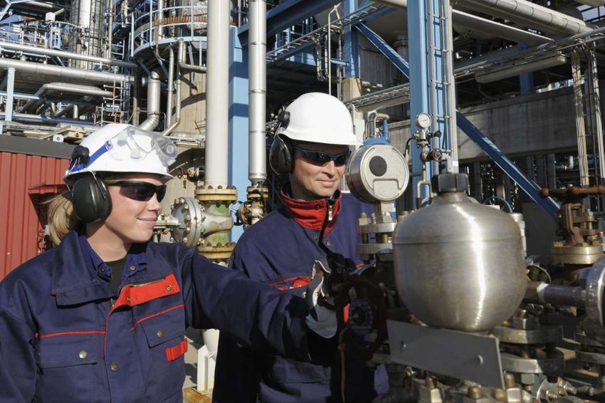
Table of content

               Electronic part library                            4       Overview of control units        51
               Lubricants suitable for lubrication systems        5        IGZ / EXZT                      52
Introduction

               Multi-line lubrication systems for oil            6         EOT - 2                         54
               Multi-line lubrication systems for grease         8         LMC 2                           55
                                                                           LMC 301                         56
               Overview of multi-line oil pumps and pump units   11
                 SP / G                                          12       Overview of monitoring devices   59
                 RA    U                                         14        SP / SFE 30                     60
                 55i                                             16        EWT2A                           61
                 JM                                              18        234-13161-5                     62
                 PDYY, PDYC and PDYS                             20        2340-00000108                   63
                 PC                                              22
                 RA    M / RA B                                  24       Index                            64
                 SP / PFE                                        28

               Overview of multi-line grease pumps               31
                 PFHM-ATEX                                       32
                 RA 20 / 45                                      34
                 P 205                                           36
                 FF                                              38
                 P 212                                           40
                 P 215                                           42
                 FB / FB - XL                                    44
                 FB - XL                                         46
                 P 230                                           48

                                                                      2
Navigation

             Introduction                      2

                                                    Introduction
             Pumps and pump units for oil      11

             Pumps and pump units for grease   31

             Control units                     51

             Monitoring devices                59

                                  3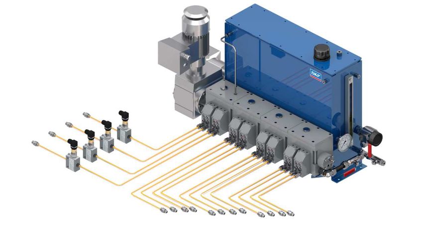
Electronic part library

               CAD product data
Introduction

               Find your parts online
               3D CAD data, technical drawings and data sheets of SKF
               automatic lubrication system components are now available
               in native format in the online parts library In addition to
               enjoying easy CAD downloads, you can configure more com-
               plex lubrication system products and integrate them into your
               design process – completely free of charge Integrate CAD
               data seamlessly into your layout plans without any delay               https://skf-lubrication partcommunity com

               Use the parts library app
               In addition to the electronic parts library, SKF offers a mobile
               app that allows you to use the SKF CAD download portal for
               lubrication systems The LubCAD app lets you view, configure
               and download products and parts in the most common CAD
               file formats You can also download related product brochures
               or find an authorized distributor in your area                         Apple App Store                Google Play

                                                                                  4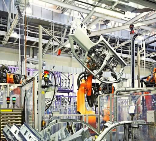
Lubricants suitable for lubrication systems
fluidfluid semi-fluid
semi-fluid non-fluid
non-fluid
Introduction
Fluid
Fluid
OilOil Grease
Grease
grease
grease
ISO VG
ISO VG 3 3 10 10 32 32100 100320 320680 680
1 5001 500
2 2002 200
3 2003 200
NLGI grades
NLGI grades 000 00000 00 0 0 1 1 2 2 3 3 4 4
Oil and
andfluid
fluidgrease
grease
The viscosity
The viscosityisisananexpression
expression of aoffluid’s
a fluid’s internal
internal friction.
friction. Oils are
Oils are
classified
classifiedininISO
ISOVGVG viscosity classes
viscosity classesfrom 2 to 23 to
from 200. NLGI NLGI
3 200 gradegrade
000, 00 and00
000, 0
greases are called fluid greases. Different types of oils are available, including
and 0 greases are called fluid greases Different types of oils are availa-
mineral oils, organic oils and synthetic oils. A compatibility check is recom-
ble, including
mended prior tomineral
using anyoils,
oilorganic
with SKFoils and synthetic
lubrication systems.oils A compatibility
check is recommended prior to using any oil with SKF lubrication
systems
Grease
Grease
Greases
Greasesare areconsistent
consistentlubricants (NLGI
lubricants grade
(NLGI 1–6).1–6)
grade They They
are soft
aretosoft
hard,totri-
hard,
ple-component mixtures of a base oil as the lubricating fluid, a thickening agent
triple-component mixtures of a base oil as the lubricating fluid, a thick-
and additives. In most instances, greases of NLGI grade 1 up to 3 are suitable for
ening
use in aagent and additives
lubrication system. AIn most instances,
compatibility greases
check should beof NLGIprior
made grade 1 up
to using
to 3 are suitable for use in a lubrication
any grease with SKF lubrication systems. system A compatibility check
should be made prior to using any grease with SKF lubrication systems
5
Multi-line lubrication systems for oil
Introduction

               System description
               SKF multi-line lubrication systems consist of the following          SKF multi-line oil pumps are designed for demanding appli-
               components: a pump unit, control and monitoring devices,             cations in nearly all industries and for pressure requirements
               tubing and fittings. Multi-line pump units supply lubricant to       up to 4 000 bar (58 000 psi)
               lubrication points without extra metering dividers. Thus, each
               lubrication point has its own pumping element. The system
                                                                                    Advantages:
               design is simple, accurate and most reliable.
               Multi-line pumps can be actuated mechanically, electrically or       • Sturdy; durable pump series designed for 24/7 operation
               hydraulically. The easily exchangeable pumping elements are          • Simple; continuous lubrication without electrical cycle
               usually operated by eccentric cam. Depending on drive speed,           timers, in most cases
               gearbox ratio and selected pump element size, a delivery             • Versatile; select individual pump element characteristics
               range from almost 0 to 227 cm3/min (0 to 13,85 in3/min) can            and oil reservoir size
               be covered
                                                                                    • Precise; set the required stroke volume at the
               By selecting pumping elements with different piston diame-             pumping element
               ters and/or stroke settings, an individual lubrication volume
               setting per pump outlet is possible The potential number of          • High delivery speed in milliseconds for timed
               outlets ranges from 1 to 28                                            and pinpointed lubrication (PD series)
                                                                                    • Broad viscosity range due to special
                                                                                      designs and small piston clearance
                                                                                    • ATEX explosion-proof versions available
                                                                                    • Extra, downstream-located flow control valves or
                                                                                      progressive metering devices possible

                                                                                6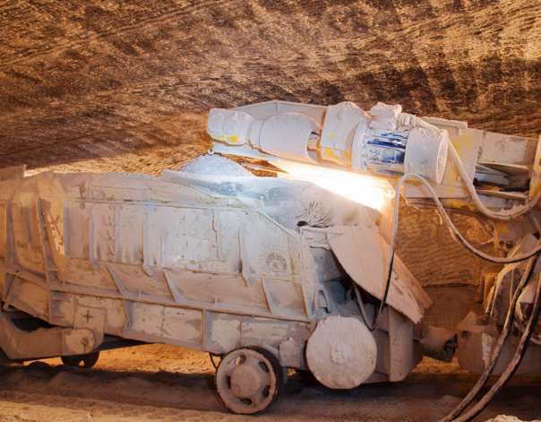
Introduction
Applications
SKF Multi-line oil pumps are sophisticated and have a long
tradition going back to applications in steam-driven locomo-
tives. Currently, they deliver the superior reliability standard
required in high-stressed machines in sensitive areas with
extreme vibrations, specially formulated oils, high lubrication
point back pressures or certain safety regulations such as:

• Vacuum pumps, compressors (all types) and the
  hyper-compressor industry
• Combustion engines for valve and cylinder liner lubrication
• Important oil total-loss or very small oil circulation
  applications
• Rubber-mixing machinery, supply of critical plasticizer oil
• Meet ATEX and API standards in the oil and gas industry

                                                                   7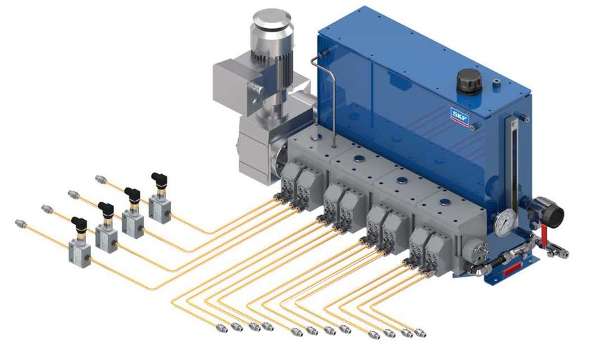
Multi-line lubrication systems for grease
Introduction

               System description
               SKF multi-line lubrication systems consist of the following          SKF multi-line grease pumps are designed for demanding
               components: a pump unit, control and monitoring devices,             applications in nearly all industries Most pump versions are
               tubing and fittings. Multi-line pump units supply lubricant to       available with special reservoirs for oil The P 215 and P 230
               lubrication points without extra metering dividers. Thus, each       pump series enable the use of plasticizer oil for the
               lubrication point has its own pumping element. The system            rubber industry
               design is simple, accurate and most reliable.
               Multi-line pumps can be actuated mechanically, electrically or       Advantages:
               hydraulically. The easily exchangeable pumping elements are          • Sturdy; durable pump series designed
               usually operated by eccentric cam. Depending on the drive              for 24/7 operation
               speed, gearbox ratio and selected pump element size, a deliv-
               ery range from almost 0 to 35 cm3/min (0 to 2 13 in3/min) can        • Simple; continuous lubrication without
               be covered The built-in stirrer mixes the grease (grease sof-          electrical cycle timers, in most cases
               tening process), is synchronized with the pump element suc-          • Versatile; select individual pump element
               tion stroke, and assists the heavy lubricant to flow into the          characteristics and reservoir size
               suction chamber This unique concept supplies heavy lubri-            • Precise; set the required stroke volume
               cants usually up to NLGI 3                                             at the pumping element
               An individual lubrication volume setting per pump outlet is          • Due to the use of a built-in stirrer and
               possible by selecting pumping elements with different piston           broad viscosity range, heaters are not required
               diameters and/or stroke settings The potential numbers of
               outlets range from 1 to 30                                           • ATEX explosion-proof versions available
                                                                                    • Extra, downstream-located flow control valves
                                                                                      or progressive metering devices possible

                                                                                8
Introduction
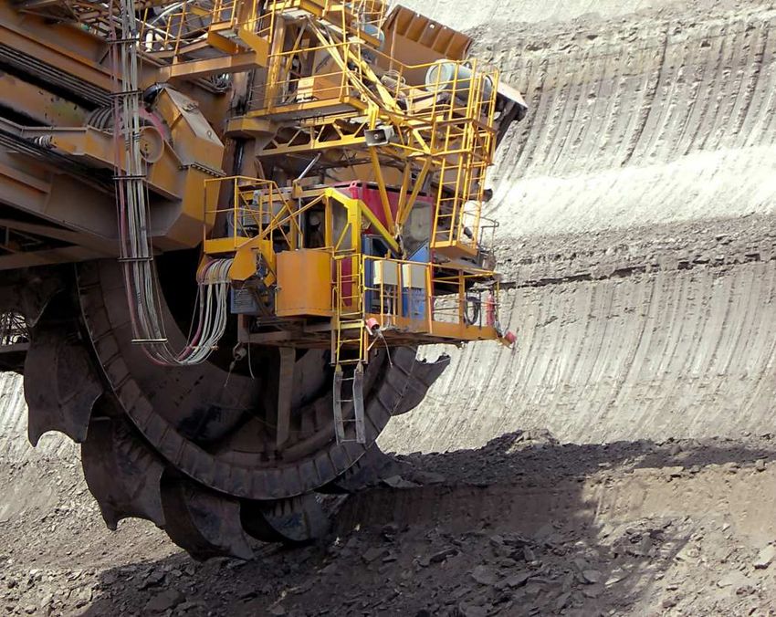
Applications
SKF Multi-line grease pumps have a long tradition in the
heavy steel industry and meet ATEX standards for gas and
dust. Their reliability standard is specified for high-stressed
machinery in sensitive and/or dirty areas with pressure
requirements up to 350 bar (5 075 psi) such as:
• Construction and mining machinery
• Tunnel-boring machines
• Forging, bending, forming
and cutting presses
• Crushers, cranes and conveyors
• Pumps and compressors
• Rubber-mixing machinery
• Water and slurry pumps
9
Pump units
     Pumps and pump
                for oil units for oil

10
Overview of multi-line oil pumps and pump units
Pump units for oil
Mechanically operated pumps
Product Outlets Reservoir Metering quantity per outlet Operating pressure max ATEX 1) Page
l gal cm3/min in3/min bar psi
SP / G 2 or 4 on request on request 0,14 – 2,9 0.008 – 0.176 3 44 – 12
RA … U 1 – 20 on request on request 0,07 – 36 0.004 – 2.196 63 913 • 2) 14
55 i 1 – 14 1–8 0.26 – 2.1 0,2 – 12,7 0.012 – 0.775 400 5 800 – 16
JM 1 – 28 2 – 14; any 0.5 – 3.7; any 0,17 – 5,0 0.010 – 0.305 600 8 700 • 3) 18
SP / PFE 1–5 on request on request 1,0 – 75,0 0.06 1– 4.576 4 000 58 000 • 3) 28
1) on request
2) for gas: II 2G c IIC T4 Gb; for dust: II 2D c IIIC T 135°C Db
3) for gas: II 2G c IIC T4 Gb
Hydraulically operated pump units
Product Outlets Reservoir Metering quantity per outlet Operating pressure max Page
l gal cm3/min in3/min bar psi
PD … 4 – 10 – – 0 – 20 0 – 1.22 63 913 20
PC 1 – 28 – – 1,74 – 227 0.106 – 13,852 50 725 22
Electrically operated pumps
Product Outlets Reservoir Metering quantity per outlet Operating pressure max ATEX 1) Page
l gal cm3/min in3/min bar psi
RA … M / RA B 1 – 20 0,3 – 15, any 0.8 – 4; any 0,07 – 36 0.004 – 2.196 60 870 • 2) 24
PC 1 – 28 – – 1,74 – 227 0.106 – 13.85 50 725 – 22
JM 1 – 28 2 – 14; any 0 5 – 3 7; any 0,15 – 7,95 0.009 – 0.485 600 8 700 • 3) 18
SP / PFE 1–5 on request on request 1,0 – 75,0 0.061 – 4.576 4 000 58 000 • 3) 28
1) on request
2) for gas: II 2G c IIC T4 Gb; for dust: II 2D c IIIC T 135 °C Db
3) for gas: II 2G c IIC T4 Gb
11Pump
SP / G
Pump units for oil
Product description
Technical data
The SP/G rotary-driven, multi-line piston pump features a
Function principle mechanically operated piston pump
fixed internal gear ratio of 33:1 Its compact pump design with Metering quantity 1) piston K 6:
only two rotating/movable parts is slide operated and requires max 0,042 cm3/stroke
no rubber seals, springs or additional non-return valves The max 0.0026 in3/stroke
piston K 7:
SP/G is available as a self-priming pump or as a pump with max 0,058 cm3/stroken
priming pressure Designs with two or four outlets are availa- max 0.0035 in3/stroke
ble The two-outlet version is offered in two different piston Group size 2, 4, 6, 8, 10 flow meters
Lubricant mineral, synthetic, environmentally safe
sizes respective of delivery volumes One vibration-proof, oil; up to 12 to 800 mm2/s
stroke-regulating screw per outlet pair enables fine-tuned Operating pressure 3 bar; 43 psi, plus inlet pressure
stroke settings Inlet pressure 0 or 2 to 6 bar,
0 or 30 to 85 psi
Operating temperature max 100 °C; 212 °F
Outlets 2 or 4
Features and benefits Internal ratio 30:1
Drive speed 300-3 000 min-1
• Virtually maintenance-free, vibration-proof, 24/7 design Drive direction left/right
Connection in/outlet for tube ∅ 4 and 6 mm OD
• Designed for high ambient temperatures and Dimensions 2 outlets:
all standard lubrication oils 56 × 88,5 × 44 mm
2.22 × 3.5 × 1.8 in
• Machine operated; no under- or over-lubrication 4 outlets:
69 × 85 × 45 mm
• Oil supply from machine sump or from existing 2.7 × 3.4 × 1.8 in
oil-circulation system Mounting position any
Options customized pre-set volumes
• Adjustable output
• Available for two drive directions 1) With priming pressure increased delivery volume; see technical information
NOTE
Applications
For further technical information, technical drawings,
• Marine industry; inlet valve seat lubrication accessories, spare parts or product function descriptions,
for powerful four-stroke engines see the following publication available on
• General machine-driven applications SKF com/lubrication: 951-170-219-EN
12Pump
SP / G
Pump units for oil
Identification code SP / G / 30
Product series
SP / G
Outlets
02 = 2
04 = 4
Gear ratio
30 = 30:1
Oil inlet design
S = self-priming suctional operation
V = pressure tight for overhead reservoirs or priming pump
Piston size
6 = piston K6, 6 mm OD
7 = piston K7, 7 mm OD
SP / G tube connections SP / G coupling element with snap ring
Order number Description Order number Description Item
Inlet screw unions
406-001 double-tapered ring for 44-1202-2038 coupling element 1
tube ∅ 6 mm OD
44-0606-6302 snap ring for 2
406-002 socket union M 10 × 1 – coupling element
tube ∅ 6 mm OD
Outlet screw unions
404-001 double-tapered ring for
tube ∅ 4 mm OD
404-002 socket union M 8×1 tube
∅ 4 mm OD
13Pump
RA ... U
Pump units for oil
Product description
Technical data
The RA multi-line pump is a unique radial piston pump with
stackable pump elements The modular pump design allows Function principle radial piston pump with stackable
pumping elements
up to five pump elements, each with one, two or four outlets Operating temperature –15 to 80 °C, +5 to +176 °F,
A later outlet reduction or outlet extension is thus possible Operating pressure 10 to 63 bar, 145 to 915 psi
The displacement of all outlets from a pump element is depending on drive speed
adjustable by a common setting device, setting range and oil viscosity
Outlets 1 to 20
33–100% Several different mechanical or electric (max 5 elements with 1, 2 or 4 outlets)
motor drives are available Lubricant mineral- and synthetic-based oil,
25 to 2 500 mm2/s
Metering quantity per outlet 0,007–0,02 cm3/revolution
Features and benefits 0.0004–0.0012 in3/revolution
Output per outlet 0,07–36 cm3/min
• Modular pump-to-point solution for 1 to 20 0.004–2.2 in3/min
Internal ratio 1:1, 5:1, 10, 5:1, 15:1, 25:1, 75:1, 125:1
lubrication points Dimensions min 113 × 54 × 54 mm
max 220 × 54 × 54 mm
• Depending on drive speed respective of selected drive ratio, min. 4.45 × 2.13 × 2.13 in
RA pumps cover feed rates of some droplets until max. 8.68 × 2.13 × 2.13 in
36 cm3 / min (2.2 in3 / min) Drive speed 10 to 1 800 min-1
Protection class min IP 55
• Drive direction left or right Mounting position any
Options with manual hand crank for pre-lubrica-
• Compatible with mineral- and synthetic-based oil tion, customized pre-set volume version
with two inlet sections for two different
• Vibration-proof, marine and ATEX versions available oil types
• Supplies several different lubrication zones,
lubrication points or chain pins
Applications NOTE
For further technical information, technical drawings,
• Gas compressors and large pumps
accessories, spare parts or product function descriptions,
• Economic power unit for sealing oil systems see the following publications available on
• Marine, valve-seat lubrication on large SKF com/lubrication:
four-stroke engines 11103 EN, 951-170-230 EN
CAD data
skf-lubrication partcommunity com/3d-cad-models/
14Pump
RA ... U
Pump units for oil
Identification code RA 0001
Product series 1 2 3 4 5
RA = radial piston pump
Drive; rotary
1UA = coaxial without gear reduction
3UA = coaxial with gear reduction
2UB = bevel gear
Ratio
00 = 1:1 (only for 1UA drive)
01 = 10 5:1 (only for 3UA drive)
05 = 5:1
15 = 15:1
25 = 25:1
75 = 75:1
13 = 125:1
Drive location
/ = coaxial
A = drive location A (only for 3UA drive)
B = drive location B (only for 3UA drive)
Pump elements, define max 5 elements
1 = 1 element with 1 outlet
2 = 1 element with 2 outlets
4 = 1 element with 4 outlets
Pre-lubrication
D = pre-lubrication (only for 2UB drive)
/ = without pre-lubrication crank
Drive direction
R = right (2UB drive with pre-lubrication only)
L = left
Design key
0001 = standard including FPM seals
RA pump elements
Order number Description
24-1557-3520 pump element, with 1 outlet
24-1557-3521 pump element, with 2 outlets
24-1557-3522 pump element, with 4 outlets
15Pump
55i
Pump units for oil
Product description
Technical data
The positive-displacement, single-action 55i pumps are fully
Function principle camshaft-operated piston pump
adjustable by means of manually modifying the angle of the Metering quantity K 3/16: 0,20 cm3, 0.0122 in3
rocker arm to the cam The pump operation is a two-stage K 1/4: 0,302cm3, 0.0184 in3
process As the camshaft rotates, the cam mechanically K 3/8: 0,68 cm3, 0.0415 in3
Outlets 1 to 7
forces the pump plunger forward, displacing a measured Lubricant mineral- or synthetic-based oil,
volume of oil On the second or return stroke, a spring assists viscosity max 1 700 mm2/s
the plunger to return for prime All pump elements are Operating pressure K 3/8: max 240 bar, 3 500 psi
K 1/4: max 400 bar, 6 000 psi
designed with a pushbutton for manual pre-lubrication Operating temperature –20 to +70 °C, –4 to + 158 °F
Reservoir 1,4 to 3,8 l, 0.37 to 1.0 gal
depends on outlet quantity
Features and benefits Internal ratio 37 5:1; 60:1; 112 5:1
Drive speedPump
55i
Pump units for oil
Identification code 55 i
1 2 3 4 5 6 7
Product series
55 i = camshaft-operated piston pump
Reservoir
3 = 1,4 l, 3 pint, max 3 single pumps
4 = 1,9 l, 4 pint, max 5 single pumps
8 = 3,8 l, 8 pint, max 7 single pumps
Drive / gear ratio / available reservoir size / speed
Designation Drive Ratio Reservoir Speed
l pt min-1
A = rotary drive, internal gear and ratchet right or left 37,5:1 1,9 4.8 700
3,8 9.6
B = internal ratchet and external lever right or left 75 1,9 4.8 1 100
teeth 3,8 9.6
C = internal super gear, pulley,machine drive right or left 112,5:1 1,9 4.8 1 200
3,8 9.6
D = external gear drive, specific OEM frame right or left 60:1 1,9 4.8 1 200
Single Pumps
Designation Piston ∅ Inlet Sight Operating pressure Metering quantity Order number
glass max per stroke max spare part
mm inch bar psi drops cm3 in3
1 = vacuum feed 6,4 1/
4 suction tube • 400 6 000 9 0,302 0.0184 880550
2 = vacuum feed 9,5 3/
8 suction tube • 240 3 500 21 0,680 0.0415 880560
3 = pressure inlet, manifold feed 4,8 3/
16
1/ NPTF
8 • 400 6 000 6 0,200 0.0122 880553
4 = pressure inlet, manifold feed 6,4 1/
4
1/ NPTM
8 • 400 6 000 9 0,302 0.0184 880551
5 = pressure inlet, manifold feed 9,5 3/
8
1/ NPTM
8 • 240 3 500 21 0,680 0.0415 880561
6 = direct feed 6,4 1/
4
1/ NPTF
8 - 400 6 000 9 0,302 0.0184 880552
7 = direct feed 9,5 3/
8
1/ NPTF
8 - 240 3 500 21 0,800 0.0488 880554
55i accessories
Description Order number
lubricator flow switch; monitors model 55i lubricant flow 880463
lube sentry; monitors camshaft rotation and reservoir level 880555
lube sentry; same as model number: 880555, except suction is 1/2 inch shorter, for pre-warning 880556
oil-level regulator; automatically fills lubricator reservoir from header reservoir 880496
cover plate; gasket 350654
cover plate assembly 250132
cover plate screws 70224
armored sight glass kit 276517
17Pump unit
JM
Pump units for oil
Product description
Technical data
The multi-line JM oil lubrication pump is a high-pressure
Function principle cam-operated piston pump in modular
pump that provides a maximum continuous operating pres- design, rotary or electrically operated
sure of 600 bar (8 700 psi) Its modular design features Metering quantity per stroke 0,017–0,2 cm3, 0.001–0.012 in3
unique, adjustable, dual-piston pumping elements (separate Outlets 1 to 28
Lubricant mineral- or synthetic-based oil,
dosing and high-pressure booster piston) in combination with 25 to 3 000 mm2/s
an optical drip indicator that delivers outstanding reliability Operating pressure max 600 bar, 8 700 psi
Operating temperature 0 to +40 °C, +32 to +104 °F
Depending on the application, the pump can be machine Protection class min IP 55F, ATEX available
or electrically driven The JM pump is available in a pres- Reservoir per module 2 l, 0 5 gal
Internal ratio 1:1, 35 1:1, 62 8:1, 83 2:1, 100 9:1,
sure-tight design that is suitable for use with overhead lubri- 125 7:1
cation oil tanks It can deliver all mineral oils with an operating Drive speed main shaft n2 10 to 25 min-1
viscosity between 25 and 3 000 mm2/s Metering quantity per outlet 0,17–5,0 cm3/min,
0.01–0.305 in3/min
Drive 3-phase motor or mechanical
Outlet connections G 1/4, tube ∅ 6 or 8 mm OD
Features and benefits Dimensions min 315 × 200 × 260 mm
max 1 455 × 200 × 260 mm
• Designed for 24/7 operation min. 12.4 × 7.87 × 10.24 in
• Three piston sizes cover output from 0,17 to 5,0 cm3/min max. 57.3 × 7.87 × 10.24 in
Mounting position horizontal, level surface
(0.01 to 0.29 in3/min) per outlet Options pressure-tight design for overhead
reservoirs, additional oil reservoir with
• Individual outlet settings between 25 and 100% heater and oil-level sensor, camshaft
rotation sensor, oil flow pulse transmit-
• Pressure-tight design available ters in ATEX
• Can be monitored according to API 618 standards
• Most reliable replacement for all standard box lubricators
Applications NOTE
For further technical information, technical drawings,
• Reciprocating gas compressors, accessories, spare parts or product function descriptions,
mainly in an ATEX environment see the following publication available on
• Pump-to-point lubrication of packings and cylinders SKF com/lubrication:
• Petro-chemical and food and beverage industry 951-170-019; 951-180-073; 14600; 1-3007
18Pump unit
JM
Pump units for oil
Identification code JM – 3M – A AG07
Product series
Oil reservoir 1) and number of outlets
02 = 2 l, 0.53 gal, max. 4 outlets
04 = 4 l, 1.1 gal, max. 8 outlets
06 = 6 l, 1.6 gal, max. 12 outlets
10 = 10 l, 2.6 gal, max. 20 outlets
12 = 12 l, 3.2 gal, max. 24outlets
14 = 14 l, 3.7 gal, max. 28 outlets
14 24 = twin version with drive M, max. 28 outlets
Oil reservoir
A = pressure tight, feed by overhead reservoir 1)
B = ventilated
Drive type
3M = E-motor operated including gear reduction 2)
Gear ratio 1)
39 = 35 1:1
57 = 62 8:1
78 = 83 2:1
98 = 100 9:1
13 = 125 7:1
Drive
A = left
B = right
M = middle (left max 24 outlets, right max 24 outlets)
Metering quantity, selection of pump element size
1 = 0,025–0,10 cm3, 0.0015–0.006 in3
2 = 0,05–0,20 cm3, 0.003–0.012 in3
3 = 0,017-0,07 cm3, 0.001–0.004 in3
0 = mixed design, please specify
Outlets
01 = 1 outlet
28 = total number of outlets
Connection outlet for tube ∅ OD
W = 8 mm solderless
X = 8 mm solderable
Y = 6 mm solderless
Z = 6 mm solderable
– = G 1/4 female, stainless steel
Modification index
A = standard
Design key 1)
0001 = basic design
4068 = ATEX II 2G c IIC T4 Gb
Motor code 1)
AG07 = E-motor 1 000 min-1; 1 500 min-1 on request available
protection class: IP 55F
1) For supply via additional or overhead reservoir (max installation height of 10 m; 5 m in conjunction with an additional reservoir in steel design)
2) For direct machine-operated versions, please consult technical support
19Pump unit
PDYY, PDYC and PDYS
Pump units for oil
Product description
Technical data
Designed for high-speed cylinder lubrication on two-stroke
Function principle electrically/hydraulically operated
engines, the PDY pumps use an existing oil supply system multi-outlet pump
or drive pump unit Engine electronics trigger the pre-loaded Metering quantity 40 to 310 mm3
pumps by activating the solenoid valve The exact stroke vol- 0.0024 to 0.019 in3
Outlets PDYS:4
ume can be synchronized with the moving engine piston, and PDYY, PDYC: 6 or 8
ignition timing can be adjusted to reach various piston stress Lubricant mineral-based oil up to SAE50;
areas with oil PDYY and PDYC pumps feature a baseplate 25 to 2 000 mm2/s
Drive oil PDYS:
configuration with 6 or 8 outlets PDYS pumps have dou- supply unit with lubricating oil
ble-stroke functionality for use on small-bore engines with PDYY, PDYC:
only 4 outlets per cylinder mineral-based system oil up to SAE30
Operating pressure 45 to 55 bar; 650 to 800 psi
Operating temperature +5 to 70 °C; +41 to 158 °F
Injection time PDYS, :Pump unit
PDYY, PDYC and PDYS
Pump units for oil
Identification code -
Product series
PDYY = electrically/hydraulically operated pump; (CLU4)
PDYC = electrically/hydraulically operated pump; compact design (CLU4C)
PDYS = electrically/hydraulically operated pump; small design (CLU5)
Outlets
04 = 4 outlets
06 = 6 outlets
08 = 8 outlets
Engine bore size
35 = 35 cm, 13.78 in
40 = 40 cm, 15.75 in
96 = 96 cm, 37.79 in
XX = engine size independent
Accumulator
A = 0,75 l, 0.2 gal for PDYY
B = 0,32 l, 0.085 gal, for PDYC
X = without
Metering quantity per stroke
PDYS: PDYY, PDYC:
40 = 40 mm3; 0.0024 in3 90 = 90 mm3; 0.0055 in3
60 = 60 mm3; 0.0037 in3 110 = 110 mm3; 0.0067 in3
150 = 140 mm3; 0.0092 in3
310 = 310 mm3; 0.019 in3
Outlet connection for tube ∅ OD
A = 6 mm C = 10 mm
B = 8 mm / = without outlet connection
Design key
0201 = basic version without bracket
4XXX = special version
Solenoid valve
24DC = voltage 24 V DC
PDYY, PDYC and PDYS accessories
Order number Pump Description
161-140-050+924 PDY/Y/C solenoid valve
161-140-056+924 PDYS solenoid valve
24-1884-2324 PDY/Y/C pressure sensor
24-1884-2397 PDYS pressure sensor
24-2578-2041 PDYC accumulator: 0,32 l; 0.085 gal
24-2578-2044 PDYY accumulator: 0,75 l; 0.2 gal
21Pump unit
PC
Pump units for oil
Product description
Technical data
Designed for total-loss lubrication systems with significant oil
Function principle modular electrically or hydraulically
volume requirements, the PC pump unit features from 1 to 28 operated piston pump unit in marine
outlets Delivery volume can be sub-divided using a progres- standard, with non-flow sensors and
sive-type metering device, enabling the pump to cover up to oil-heating connections
Metering quantity per outlet 1,74–227 cm3/min, 0.1–14 in3/min
224 lubrication points This all-in-one pump unit consists of a Outlets 1 to 28
frequency-controlled E-motor with gear reduction, pump Lubricant mineral oil up to SAE 5012
modules with pumping elements for six pre-defined settings, to 2 000 mm2/s
Lubricant supply by overhead reservoir,
optical/electrical flow controls, additional sensors for low level max inlet pressure 2 bar, 30 psi
and optional drive speed, safety valves and connections for Operating pressure max 50 bar, 725 psi
heating oil Its integrated shut-off valves, one per module, Operating temperature +5 to 45 °C, +41 to 113 °F
Internal ratio 4 83; 14 5; 19; 29; 38; 51; 62 : 1
allow the use of different lubricating oil and/or pumping ele- Output per Outlet 0,27–1,1 cm3,0 016–0 067 in3
ment replacement during operation The terminal box with Electrical connection Sensor 24 V DC
Hydraulic drive option 100 cm3/revolution, 60–360 min-1 for
pre-wired sensors contains a pushbutton for pre-lubrication i = 4 81:1 and 7 25:1 only
Protection class IP 55F
Connection inlet: G 11/4
Features and benefits outlet: G 1/4 for tube ∅ 10 mm OD
Dimensions min 610 × 513 × 320 mm
• Accurate, robust lubrication pump assembly max 610 × 1 580 × 320 mm
min. 24 × 20.2 × 25.6 in
• Load-dependent, variable-speed operation as standard max. 24 × 62.2 × 25.6 in
Mounting position horizontal
• E-motor with electrically operated air fan enables wide Options version with mainshaft revolution;
speed range sensor; sensors NPN instead of NAMUR
• Ease of operation, maintenance and assembly
• Assembly brackets for hanging or standing position
• 24/7 operation in arctic and tropical conditions
NOTE
For further technical information, technical drawings,
Applications accessories, spare parts or product function descriptions,
• Marine industry see the following publication available on
SKF com/lubrication:
951-170-208
22Pump unit
PC
Pump units for oil
Identification code PC A 1 C
Product series
Size
2 = 2 modules, max 8 outlets 5 = 5 modules, max 20 outlets
3 = 3 modules, max 12 outlets 6 = 6 modules, max 24 outlets
4 = 4 modules, max 16 outlets 7 = 7 modules, max 28 outlets
Mounting plate position
B = top (floor)
R = rear (rear wall)
Drive type
1M = worm drive with electric motor
1Y = worm drive with hydraulic motor
Pump location and front label design
VM = front side mounted, multi level, 1 upper level, 1 lower level, 2 upper level
VS = front side mounted, single level, 1, 2, 3, 4 x
HM = rear side mounted, multi level, × 4 upper level, 4 lower level, 3 upper level
HS = rear side mounted, single level, × 4, 3, 2, 1
Gear reduction
14 = 14,5:1 for drive type 1M 51 = 51:1 for drive type 1M
19 = 19:1 for drive type 1M 62 = 62:1 for drive type 1M
29 = 29:1 for drive type 1M 05 = 4,83:1 for drive type 1Y
38 = 38:1 for drive type 1M 07 = 7,25:1 for drive type 1Y
Drive position
A = motor at left
Pump element
1 = piston ∅ 10 mm
Outlets
01 = 1 outlet; 28 = 28 outlets
Outlet connection for tube ∅ OD
C = 10 mm
Design key
A0001 = basic version, electric motor with GL approval, NAMUR sensor incl terminal box, colour Munsel 7,5 BG7/2
A0002 = basic version, with tachometer
A0003 = basic version, sensor type NPN instead of NAMUR
A4002 = basic version, sensor type NPN instead of NAMUR, without terminal box
A4003 = basic version, sensor type NPN instead of NAMUR, without terminal box, with revolution sensor
A4004 = basic version, including oil troy and mounting bracket
A4005 = same as A0003, with revolution sensor
Motor code
AS07 = 3-phase standard motor 255/460 V 60 Hz, n = 1 740 min-1, IP 55F
HM00 = hydraulic motor Danfoss OMR100
PC accessories
Order number Description
24-0404-2493 gasket set with seals
24-1557-3560 spare pumping element
24-1751-2760 filter assembly, 100 mµ
24-0651-3519 filter element only
23Pump unit
RA ... M / RA B
Pump units for oil
Product description
Technical data
The RA radial piston pump features a modular design that
Function principle radial piston pump with stackable
enables use of up to five stackable pump elements, and outlet pumping elements, mechanically or
reduction or expansion can be accomplished easily Displace- electrically operated
ment of all outlets from a pump element is adjustable by a Outlets 1 to 20
(max 5 elements with 1, 2 or 4 outlets)
common setting device and features a setting range of Metering quantity per outlet 0,007–0,02 cm3/revolution
33-100% The RA B series pump have a pre-assembled 0.0004–0.001 in3/revolution
oil reservoir Output per outlet 0,07–36 cm3/min
0.004–2.2 in3/min
Internal ratio 1:1, 5:1, 10, 5:1, 15:1, 25:1, 75:1, 125:1
Lubricant mineral- and synthetic-based oil,
Features and benefits 25 to 2 500 mm2/s
Reservoir 3, 7, 15 l and more,
• Pump-to-point solution for 1 to 20 lubrication points 0 8, 1 8, 4 gal and more
Operating pressure 10 to 63 bar, 145 to 913 psi
• Covers feed rates of certain droplets 36 cm3/min depending on drive speed
• Compatible with mineral and synthetic oils and oil viscosity
Operating temperature –15 to 80 °C, +5 to 176 °F
• Vibration-proof, marine and ATEX versions available electrically operated:
–15 to 40 °C; +5 to +104 °F
Protection class min IP 55
Drive speed 10 to 1 800 min-1
Applications Connection in/outlet G 1/8
E-motor drive with 3-phase motor
• Gas compressors and large pumps Drive direction left/right
• General industry, total loss, sealing and small Dimensions without reservoir:
min 113 × 54 × 54 mm
oil-circulation applications max 220 × 54 × 54 mm
min. 4.45 × 2.13 × 2.13 in
• Marine max. 8.68 × 2.13 × 2.13 in
with reservoir:
min 400 × 333 × 140mm
NOTE max 650 × 441 × 288 mm
min. 15.7 × 13.1 × 5.5 in
For further technical information, technical drawings, max. 25.6 × 17.4 × 11.3 in
accessories, spare parts or product function descriptions, Mounting position any, RAB versions vertical
see the following publications available on Options with manual hand crank for pre-
lubrication, customized pre-set
SKF com/lubrication: volume, reservoir options with
11103 EN, 951-170-230 EN further accessories
CAD data
skf-lubrication partcommunity com/3d-cad-models/
24Pump unit
RA ... M
Pump units for oil
Identification code RA / R 0001 07
Product series 1 2 3 4 5
RA = radial piston pump
Drive; rotary
1M = coaxial without gear reduction
3M = coaxial with gear reduction
2M = bevel gear
Ratio
00 = 1:1 (only for 1M drive)
01 = 10 5:1 (only for 3M drive)
05 = 5:1
15 = 15:1
25 = 25:1
75 = 75:1
13 = 125:1
Drive location
/ = standard
Pump elements, define max 5 elements
1 = 1 element with 1 outlet
2 = 1 element with 2 outlets
4 = 1 element with 4 outlets
Pre-lubrication
D = pre-lubrication (only for 2M drive)
/ = without pre-lubrication crank
Drive direction
R = right
Design key
0001 = standard including FPM seals
Motor Code 1)
AF = standard multi-range motor, 1 500 min-1, for 230–400 V AC/50 Hz
AK = standard multi-range motor, 1 500 min-1, for 290–500 V AC/50 Hz
AO = standard multi-range motor, 1 500 min-1, for 400–690 V AC/50 Hz
Protection class 1)
07 = IP 55
1) further models on request
25Pump unit
RA B
Pump units for oil
Identification code RA B R 0001 07
Product series 1 2 3 4 5
RA B= radial piston pump with reservoir
Reservoir 1)
03 = 3 l, 0 8 gal
07 = 7 l, 1 85 gal
15-2 = 15 l, 3 96 gal
Fill-level switch
X = without
V = inclusive
Drive, E-motor
1M = coaxial without gear reduction
2M = coaxial with gear reduction
3M = bevel gear
Ratio
00 = 1:1 (only for 1M drive)
01 = 10 5:1 (only for 3M drive)
05 = 5:1
15 = 15:1
25 = 25:1
75 = 75:1
13 = 125:1
Drive location
/ = standard for 1M and 2M
A = 3M only
Pump elements max 5 elements
1 = 1 element with 1 outlet
2 = 1 element with 2 outlets
4 = 1 element with 4 outlets
Pre-lubrication
DR = pre-lubrication (only for 2M drive)
/ = without pre-lubrication crank
Drive direction
R = right
Design key
0001 = standard incl FPM seals
Motor code 1)
AF = standard multi-range motor, 1 500 min-1, for 230–400 V AC/50 Hz
AK = standard multi-range motor, 1 500 min-1, for 290–500 V AC/50 Hz
AO = standard multi-range motor, 1 500 min-1, for 400–690 V AC/50 Hz
Protection class 1)
07 = IP 55
1) further models on request
26Pump unit
RA ... accessories
Pump units for oil
RA U drive assembly RA tie rod 1) RA pump elements for oil and grease
for ratio 1:1; 10,5:1; 15:1; 25:1; 75:1
Description Order number Description Order number Description Order number
coaxial 1:1 24-0701-3000 for 1 pump element 44-0717-2060 for 1 outlet 24-1557-3520
coaxial 5:1 24-0701-3070 for 2 pump elements 44-0717-2061
coaxial 5:1 with pre-lubrication 24-0701-3080 for 3 pump elements 44-0717-2062 for 2 outlets 24-1557-3521
for 4 pump elements 44-0717-2063
bevel gear, 10,5:1, positionA 24-0701-3001 for 5 pump elements 44-0717-2064 for 4 outlets 24-1557-3522
bevel gear, 10,5:1, position B 24-0701-3002
washer, 6 4 DIN125 1) DIN125-B6 4-ST
coaxial 15:1 24-0701-3071 nut 1) DIN934-M6-8
coaxial 15:1 with pre-lubrication 24-0701-3081
coaxial 25:1 24-0701-3072
coaxial 25:1 with pre-lubrication 24-0701-3082
coaxial 75:1 24-0701-3073
coaxial 75: 1 with pre-lubrication 24-0701-3083
coaxial 125:1 24-0701-3074
coaxial 125:1 with pre-lubrication 24-0701-3084
spacer ring, only oil, for ratio 1:1 24-1721-2000
spacer ring, only grease 24-1721-2001
RA M drive assembly RA tie rod 1) RA accessories
for ratio 5:1; 125:1
Description Order number Description Order number Description Order number
coaxial 1:1 24-0701-3004 for 1 pump element 44-0717-2069 cover 24-0413-3490
coaxial 5:1 24-0701-3035 for 2 pump elements 44-0717-2070
coaxial 5:1 with pre-lubrication 24-0701-3036 for 3 pump elements 44-0717-2071 cap nut 95-0006-0917
for 4 pump elements 44-0717-2072
bevel gear, 10,5:1, positionA 24-0701-3003 for 5 pump elements 44-0717-2073 hand crank 24-0801-2070
bevel gear, 10,5:1, position B 24-0701-3004
washer, 6 4 DIN125 1) DIN125-B6 4-ST
coaxial 15:1 24-0701-3037 nut 1) DIN934-M6-8
coaxial 15:1 with pre-lubrication 24-0701-3038
coaxial 25:1 24-0701-3039
coaxial 25:1 with pre-lubrication 24-0701-3040
coaxial 75:1 24-0701-3041
coaxial 75: 1 with pre-lubrication 24-0701-3042
coaxial 125:1 24-0701-3043
coaxial 125:1 with pre-lubrication 24-0701-3044
spacer ring, only oil, for ratio 1:1 24-1721-2000
spacer ring, only grease 24-1721-2001
1) two required per pump
27Pump unit
SP / PFE
Pump units for oil
Product description
Technical data
The SP / PFE multi-line pump is designed for very high
Function principle Rotary-operated, cam-operated
system pressures Its drive parts are located in the pump piston pump; with pressure-tight design
housing and are pre-filled with high-viscosity gear oil for overhead reservoirs
The special, guided-roller tappet drives the pump element Metering quantity per outlet 0–0,14 cm3/stroke
0–0.0085 in3/stroke
arrangement in a 100% axial direction and eliminates side Outlet 1 to 5
forces Each exchangeable pumping element contains a pre- Lubricant mineral- or synthetic-based oil,
cise, volume-regulating device with scaling, a high-pressure, < 230 mm2/s
Operating pressure max 4 000 bar; 58 000 psi
non-return valve and a high-pressure outlet adapter for up Operating temperature +15 to +40 °C, +59 to 104 °F
to 4 000 bar (58 000 psi) Internal ratio 1:1
Material 3-phase motor and
Due to the pump’s unique design, lubrication oil can be flanged gearbox available
connected from an overhead reservoir directly to the pump Drive speed main shaft 1) 10 to 500 min-1
E-motor drive 1) 10 to 500 min-1
elements without the use of additional oil-level controllers
Connection outlet gland and sleeve for pipe 3/8 × 1/8
Connection inlet/leak oil M 14 × 1,5
Features and benefits outlet
Dimensions 287 × 350 × 130 cm
• Designed for continuous 24/7 operation 512 × 350 × 130 cm
11.3 × 13.8 × 5.1 in
• Modular pump design enables use of up to 20.15 × 13.8 × 5.1 in
five pumping elements Mounting position vertical, pump body upright
Options Available as ATEX package with E-motor
• Pressure-tight design; suitable for overhead drive arrangement , rack mounting,
reservoir connection flow monitoring devices
• Rack arrangement with additional pumps, 1) please specify your requirements
filter and flow control equipment available
NOTE
Applications
For further technical information, technical drawings,
• Petro-chemical industry accessories, spare parts or product function descriptions,
see the following publications available on
SKF com/lubrication:
14600EN
28Pump unit
SP / PFE
Pump units for oil
Identification code SP / PFE – – C
Product series
SP / PFE
Housing
1 = housing for 1 up to 2 pump elements
2 = housing for 1 up to 5 pump elements
Pump elements
1 = 1 pump elements
2 = 2 pump elements
3 = 3 pump elements
4 = 4 pump elements
5 = 5 pump elements
Modification index
C = actual version for pmax 4 000 bar, (58 000 psi), rotary-operated, double-sided drive shaft, ratio 1:1
Accessories SP / PFE pump outlets - SP / PFE accessories
high-pressure pipe connection required Order number Description Operating pressure max
bar psi
Dimensions
744-000-0107 high-pressure pump head complete 4 000 58 000
1 = 29° ± 30'
2 = 3/8 in 24 NF left 24-2317-2017 high-pressure piston and body only 4 000 58 000
3 = ∅ 5,5 mm
4 = 19 mm 1
2
4
3
29Pump units
Pumps unitsfor
forgrease
grease
30Overview of multi-line grease pumps
Pump units for grease
Hydraulically operated pump units
Product Lubricant Outlets Reservoir 6) Metering quantity per outlet Operating pressure Page
grease max
NLGI
0 1 2 3 kg lb cm3/min in3/min bar psi
PFHM-ATEX • • • – 1–6 6 12 0,80-5,00 0.048-0.305 250 3 625 32
Mechanically operated pump units
Product Lubricant Outlets Reservoir 6) Metering quantity per outlet Operating pressure ATEX 3) Page
grease
max
NLGI
0 1 2 3 kg lb cm3/min in3/min bar psi
RA 20 / 45 • • • – 1 – 12 2–5 4.4 – 10 0,07–6,00 0.004–0.366 60 870 • 4) 34
P 205 • • • – 1–5 4 – 30 8.8 – 66 0,08–4,20 0.005–0.256 350 5 075 • 5) 36
FF • • • • 1 – 12 4 – 10 8.8 – 22 0,04–6,90 0.002–0.421 350 5 075 • 4) 38
P 215 2) • • • – 1 – 15 4 – 100 8.8 – 220 0,55–3,15 0.033–0.192 350 5 075 • 5) 42
FB • • • • 1 – 24 6 – 30 13 – 66 0,04–7,70 0.002–0.469 350 5 075 • 4) 44
P 230 • • • – 1 – 30 30 – 100 66 – 220 0,55–3,15 0.033–0.192 350 5 075 • 48
Electrically operated pump units 1)
Product Lubricant Outlets Reservoir 6) Metering quantity per outlet Operating pressure ATEX 3) Page
grease
max
NLGI
0 1 2 3 kg lb cm3/min in3/min bar psi
RA 20 / 45 • • • – 1 – 12 2–5 4.4 – 10 0,07–6,00 0.004–0.366 60 870 • 4) 34
P 205 • • • – 1–5 4 – 30 8.8 – 66 0,08–4,20 0.005–0.256 350 5 075 • 5) 36
FF • • • • 1 – 12 4 – 10 8.8 – 22 0,04–6,00 0.002–0.366 350 5 075 • 4) 38
P 212 2) • • • – 1 – 12 30 66 2,50–25,0 0.152–1.525 350 5 075 • 40
P 215 2) • • • – 1 – 15 4 – 100 8.8 – 220 0,55–3,15 0.033–0.192 350 5 075 • 5) 42
FB • • • • 1 – 24 6 – 30 13 – 66 0,04–7,70 0.002–0.469 350 5 075 • 4) 44
FB-XL • • • • 1 – 16 30 66 0,04–35,0 0.002–2.135 350 5 075 • 4) 44
P 230 • • • – 1 – 30 30 – 100 66 – 220 0,55–3,15 0.033–0.192 350 5 075 • 48
1) all data based on 50 Hz operation for connection with a frequency of 60 Hz, the speed and volumetric flow are increased by 20%
2) NLGI 3 on request
3) on request
4) for gas: II 2G c IIC T4 Gb; for dust: II 2D c IIIC T 125°C Db
5) for gas: II 2G c IIC T4 Gb; for dust: II 2D c IIIC T 120°C Db
6) valid for ρ=1 kg/dm3
31Pump unit
PFHM-ATEX
Pump units for grease
Product description
Technical data
The PFHM-ATEX is a hydraulically operated, high-pressure
Function principle hydraulically operated radial piston
multi-line pump Its one to six pumping elements are availa- pump in an ATEX design
ble in five sizes from 0,04 to 0,25 cm3/stroke (0.0024 to Metering quantity per stroke KFG1 U0: 0,250 cm3; 0.0152 in3
0.0152 in3 /stroke) or camshaft revolution The ratio between KFG1 U1: 0,125 cm3; 0.0076 in3
KFG1 U2: 0,090 cm3; 0.0054 in3
the hydraulic motor and camshaft is generally 1:1 KFG1 U3: 0,065 cm3; 0.0039 in3
The PFHM-ATEX’s sturdy steel housing and reservoir with KFG1 U4: 0,040 cm3; 0.0024 in3
Metering quantity per outlet 0,8–5,0 cm3/min;
air breather enable use in dusty areas When utilized in com- 0.048–0.305 in3/min
bination with downstream-located progressive divider valves, Outlets 1 to 6
Lubricant oil and grease: up to NLGI 2
it can handle up to approximately 50 lubrication points The Operating pressure max 250 bar; 3 625 psi
reservoir with stirrer is suitable for both grease and oil and Operating temperature –20 to +40 °C; –14 to +104 °F
is designed for instead with a locking device Reservoir 1) 6 kg, 12 lb
Internal ratio 1:1
Drive speed main shaft 4–30 min-1
Features and benefits Hydraulic drive oil 51,5 cm3 per revolution,
requirements max 175 bar, 2 540 psi
• Sturdy design with standard, spring-return pumping
elements and ATEX classifications Outlet connection lubricant M 14 × 1,5; tube ∅ 6, 8, 10 mm
In/outlet hydraulic connection M 22 × 1,5
• Designed for 24/7 operation in harsh environments Dimensions 580 × 230 × 230 mm
22.8 × 9.1 × 9.1 in
• Varying speed and stroke volumes enable economical Mounting position vertical
lubricant settings, hydraulical drive without electrics Options C5-M
• Modular design available in corrosiveness class C3 as
1) valid for ρ=1 kg/dm3
standard or C5-M according to DIN EN ISO 12944
• Atex classification for gas, dust and mining application
as standard
NOTE
For further technical information, technical drawings,
Applications accessories, spare parts or product function descriptions,
• Mining, including underground see the following publication available on
SKF com/lubrication
• Hydraulically operated machinery
• Screens and crushers in quarries
• Chemical industry, offshore
32Pump unit
PFHM-ATEX
Pump units for grease
Order information 1)
Order number Description
PFHM-6-B6-C3-ATEX standard pump including hydraulic drive, without pumping element version C3
6 kg, 12 6 lbs reservoir;
included ATEX approval:
gas; II 2G Ex h IIC T6 T5 Gb
dust: II 2D Ex h IIIC T85°C T100°C Db
mining: I M2
PFHM-6-B6-C5-ATEX same as above, with an improved corrosion standard C5-M
included ATEX approval:
gas: II 2G Ex h IIB T6 T5 Gb
dust: II 2D Ex h IIIC T85°C T100°C Db
mining: I M2
1) Please order pump elements separately
PFHM-ATEX accessories - pump elements, spring return
Order number
C3 version C5 version Description Metering quantity 1)
cm3/stroke in3/stroke cm3/min in3/min
KFG1 U0 KFG1 U0-C5M pump element 0,250 0.0152 5,0 0.305
KFG1 U1 KFG1 U1-C5M pump element 0,125 0.0076 2,5 0.152
KFG1 U2 KFG1 U2-C5M pump element 0,090 0.0054 1,8 0.109
KFG1 U3 KFG1 U3-C5M pump element 0,065 0.0039 1,3 0.079
KFG1 U4 KFG1 U4-C5M pump element 0,040 0.0024 0,8 0.048
1) The values given are design values of the pump elements and are valid at 20 rpm, a temperature of 20 °C,
a back pressure of 50 bar and when using NLGI grade 2 greases
Pressure regulating valves
Order number
C3 version C5 version Description Pipe ∅ Opening
pressure 1)
mm bar psi
161-210-075 161-210-079 pressure regulating valve 6 250 3 626
161-210-076 161-210-080 pressure regulating valve 8 250 3 626
161-210-077 161-210-081 pressure regulating valve 10 250 3 626
1) These valves have opening tolerances of ±20%
33Pump unit
RA 20 / 45
Pump units for grease
Product description
Technical data
The RA 20/45 radial piston pump features a modular design
Function principle radial piston pump with stackable
that enables use of up to three stackable pump elements, and pumping elements, rotary
outlet reduction or extension can be achieved easily or electrically operated
Metering quantity per outlet 0,007–0,02 cm3/revolution
The displacement of all outlets from a pump element is 0.0004–0.0012 in3/revolution
adjustable by a common setting device with a range of 33 Outlets 1 to 12 (max 3 elements with
to 100% The grease reservoir contains a stirrer and screw 1, 2 or 4 outlets)
Lubricant grease: up to NLGI 2
conveyor to pressurize the grease into the suction chamber Operating peak pressure max 63 bar, 913 psi
This feature, in combination with a wide range of different Operating temperature –15 to +40 °C, +5 to 104 °F
Protection class IP 55
selectable gear ratios, enables a small and continuous Reservoir 1) 2,0 or 4,5 kg, 4.4 or 10 lb
lubricant flow without the use of extra on/off timers
Internal ratio 5:1, 10,5:1, 15:1, 25:1, 75:1, 125:1
Drive speed 10 to 245 min-1
Features and benefits E-motor drive with 3-phase motor
Outlet connection G 1/8
• Modular, pump-to-point solution for 1 to 12 Dimensions depending on the model
min 353 × 180 × 180 mm
lubrication points max 660 × 325 × 180 mm
• Suitable for standard NLGI 2 greases min. 13.9 × 7.1 × 7.1 in
max. 26 × 12.8 × 7.1 in
• Grease reservoir for 2 or 4 5 kg (4.4 to 10 lb), Mounting position vertical
Options with level switch
optional level switch
• Covers feed rates of droplets
up to 10 cm3/min (0.6 in3/min)
1) Valid for ρ=1 kg/dm3
• Simple system design with adjustable outputs
• Economical, multi-line grease pump
NOTE
Applications For further technical information, technical drawings,
accessories, spare parts or product function descriptions,
• Compact machinery see the following publication available on
• Conveyor systems SKF com/lubrication:
• Water pumps 11103 EN, 951-170-230 EN
34Pump unit
RA 20 / 45 grease
Pump units for grease
Identification code RA 07
Product series
RA = radial piston pump
Reservoir
20 = 2 kg, 4.41 lb
45 = 4,5 kg, 9.92 lb
Fill-level switch
X = none
E = with 1 switching point
F = with 2 switching points
Drive
2M = electric motor with gear reduction
3M = electric motor with bevel gear
3UA = coaxial with gear reduction
Step-down ratio
01 = 10 5:1 (3M, 3UA)
05 = 5:1; 15 = 15:1; 25 = 25:1; 75 = 75:1; 13 = 125:1 (2M)
Drive position
A = only 2M, 3M
A or B = only 3UA
Pump elements, max 3 elements
1 = 1 outlet
2 = 2 outlets
4 = 4 outlets
Design
0001 = standard
4062 = ATEX II 2G c IIC T4 Gb, II 2D c III CT 135°C
Motor 2)
AF = standard multi-range motor, 1 500 min-1, for 230–400 V AC/50 Hz
AK = standard multi-range motor, 1 500 min-1, for 290–500 V AC/50 Hz
AO = standard multi-range motor, 1 500 min-1, for 400–690 V AC/50 Hz
Protection class
07 = IP 55
1) further models on request
RA pump elements and tie rods Reservoirs
Order number Description Order number Description
24-1557-3520 pump element for 1 outlet 24-0254-2312 reservoir 2 kg, without fill-level switch
24-1557-3521 pump element for 2 outlets 24-0254-2334 reservoir 2 kg, with fill-level switch E
24-1557-3522 pump element for 4 outlets 24-0254-2330 reservoir 2 kg, with fill-level switch F
44-0717-2070 tie rod 1) for 1 pump element 24-0254-2310 reservoir 4,5 kg, without fill-level switch
44-0717-2071 tie rod 1) for 2 pump elements 24-0254-2335 reservoir 4,5 kg, with fill-level switch E
44-0717-2072 tie rod 1) for 3 pump elements 24-0254-2331 reservoir 4,5 kg, with fill-level switch F
DIN125-B6 4-ST washer, 6 4 DIN125 1)
DIN934-M6-8 nut 1)
1) Two required per pump
35Pump unit
P 205
Pump units for grease
Product description
Technical data
The P 205 high-pressure, multi-line pump can supply
Function principle electrically operated, multi-piston pump
lubricant directly to lubrication points or can be used as a cen- Metering quantity per stroke 0,04–0,23 cm3
tralized lubrication pump in large-sized progressive systems 0.002–0.014 in3
It can drive up to five elements, which are available in varying Output per outlet 0,08–4,20 cm3/min, 0.005–0.256 in3/min
Outlets 1 to 5
sizes for optimum adjustability The pump’s drive and eccen- Lubricant oil: viscosity from 40 mm2/s
tric shaft design, high-efficiency worm gear, minimal number grease: up to NLGI 2
of parts and multi-range motor provide several advantages Operating pressure max 350 bar, 5 075 psi
Operating temperature –20 to +40 °C, -4 to +104 °F
P 205 pumps are available with a three-phase flange mount Protection class IP 55
and multi-range motor or with a free shaft end for use with Materials steel plate or plastic,
other motors Various gear ratios and reservoir sizes with or depending on reservoir
Reservoir 1) plastic:
without level control are offered 4 and 8 kg, 8.8 and 17.6 lb
steel:
5, 10 and 30 kg, 11; 22 and 66 lb
Features and benefits Line connection G 1/4
Drive speed main shaft grease: < 25 min-1, oil: < 25 min-1
• Durable, versatile and reliable pump series Electrical connections 380–420 V AC/50 Hz,
440–480 V AC/60 Hz
• Suitable for grease or oil 500 V AC/50Hz
Dimensions depending on the model
• Designed for continual lubrication of machines min 406 × 280 × 230 mm
and systems operating in harsh environments max 507 × 365 × 300 mm
min. 160 × 110 × 91 in
• Broad range of output options max. 200 × 144 × 118 in
Mounting position vertical
• Modular design and easy maintenance Options several different level switches;
1) valid for ρ=1 kg/dm3
ATEX versions
Applications
• Stationary machines with a high lubricant consumption NOTE
• Turbines in hydro-electric power plants For further technical information, technical drawings,
accessories, spare parts or product function descriptions,
• Needling machines see the following publication available on
• Screens and crushers in quarries SKF com/lubrication:
• Material handling equipment 13651 EN
36Pump unit
P 205
Pump units for grease
Identification code P 205 – – – –
Product series
Drive
M = AC flange gear motor
F = free shaft end
Gear ratio
280 =280:1
700 =700:1
070 = 70:1
Reservoir
4 = plastic, 4 l, 1.05 gal
8 = plastic, 8 l, 2.11 gal
5 = steel plate, 5 l, 1.32 gal
10 = steel plate, 10 l, 2.64 gal
30 = steel plate, 30 l, 7.93 gal
Reservoir design
N = without level control
XY = for grease and oil
XL = for grease with low level control)
BU = with level control (ultrasonic sensor for two switching points, low- and high-level)
Pump elements; define max 5 elements (f i 4 elements K6 = 4K6, )
K5 = piston ∅ 5 mm, output per stroke: 0,11 cm3, 0.006 in3
K6 = piston ∅ 6 mm, output per stroke: 0,16 cm3, 0.009 in3
K7 = piston ∅ 6 mm, output per stroke: 0,23 cm3, 0.014 in3
KR = adjustable output, piston ∅ 7 mm, output per stroke: 0,04-0,18 cm3, 0.002-0.010 in3
Supplements to motor designation
320 - 420, 440 – 480 = multi-range motor for nominal supply voltage, 380-420 V AC/50 Hz, 440-480 V AC/60 Hz
500 = single-range motor for nominal supply voltage, 500 V/50 Hz
000 = pump without motor, with coupling flange
P205 pump elements Pressure-relief valve and filling connectors
Order number Description Metering quantity per Order number Description
stroke
cm3 in3
624-29056-1 pressure-relief valve, 350 bar,
G 1/4 D 6 for tube ∅ 6 mm OD
600-26875-2 pump element piston K 5 0,11 0.006 624-29054-1 pressure-relief valve, 350 bar,
G 1/4 D 8 for tube ∅ 8 mm OD
600-26876-2 pump element piston K 6 0,16 0.009
304-17571-1 filling connector G 1/4 female 1)
600-26877-2 pump element piston K 7 0,23 0.014
655-28716-1 pump element 0,04–0,18 0.002–0.010
adjustable KR (7) 304-17574-1 filling connector G 1/2 female 1)
303-19285-1 closing screw 1) – –
1) for outlet port instead of a pump element 1) filling connector fits for vacant outlet ports
37Pump unit
FF
Pump units for grease
Product description
Technical data
The multi-line pump unit of the FF series is suitable for
Function principle radial piston pump with stirrer,
small- and medium-sized systems due to its flow rate
electrically operated
and reservoir The lubricant can be fed to the lubrication Operating temperature –15 to +40 °C, +5 to 104 °F
points directly or via a progressive feeder Designed for Operating pressure 125 to 350 bar, 1 800 to 5 075 psi
Lubricant oil: mineral- and synthetic-based;
use with oil and stiff grease, the FF is a sturdy, vibration-
viscosity from 50 mm2/s
resistant pump that withstands harsh environments and grease: up to NLGI 3
continuous operation Reservoir 1) 4 and 10 kg, 8.8 and 22 lbs
Metering quantity per stroke KR 6:
0,027–0,08 cm3, 0.0016–0.0048 in3
Features and benefits KR 8:
0,05–0,15 cm3, 0.003–0.009 in3
KR 10:
• Designed for small- and medium-sized systems 0,077–0,23 cm3, 0.005–0.014 in3
Internal ratio 33:1, 80:1, 150:1, 300:1, 600:1
• Sturdy and vibration resistant Outlet connection 1/ NPTF, tube ∅ 6, 8, 10 mm OD
4
• Suitable for oils and very stiff greases E-motor drive with 3-phase motor
Drive speed main shaft < 32 min-1
• Withstands harsh operating conditions and continuous Dimensions min 450 × 370 × 230 mm
operation max 656 × 370 × 230 mm
min. 17.7 × 14.6 × 9 in
max. 25.8 × 14.6 × 9 in
Protection class IP 55
Applications Mounting position vertical
Options several different reservoir designs for oil
• Automotive industry and wind energy systems and grease, level switches,
ATEX versions, pressure-limiting valves
• Construction materials machinery
• Tunnel-driving machinery, mining and conveyor systems 1) valid for ρ=1 kg/dm3
• Paper and boxing machinery
• Steel and heavy industry; annealing machines NOTE
For further technical information, technical drawings,
accessories, spare parts or product function descriptions,
see the following publication available on
SKF com/lubrication:
14129; 951-170-201; 951-180-076
38You can also read