BG 75 PI Instruction Manual / Betriebsanleitung BLDC motor with parametrizable motion controller integrated - Bürstenloser DC-Motor mit ...
←
→
Page content transcription
If your browser does not render page correctly, please read the page content below
Instruction Manual / Betriebsanleitung
   BLDC motor with parametrizable motion controller
                       integrated
Bürstenloser DC-Motor mit integriertem parametrierbarem
                    Motioncontroller

                         BG 75 PI

                     Edition / Ausgabe (05/2009)
1 Contents 1 Contents
1 Inhalt 1 Inhalt
Page Seite
10.3 Installation of the Software 10.3 Installation der Software
1 Contents 2 1 Inhalt 2 Drive Assistant 26 Drive Assistant 26
11 Description of the Main Window 27 11 Beschreibung des Hauptfensters 27
2 About this document 5 2 Über dieses Dokument 5 11.1 Description of the General 27 11.1 Beschreibung der allgemeinen 27
Parameter Groups - Main Window 27 Parametergruppen - Hauptfenster 27
3 General description 6 3 Allgemeine Beschreibung 6 11.2 Description of the Menu Bar 27 11.2 Beschreibung der Menüleiste 27
3.1 Motor range BG 75 PI 6 3.1 Motorbaureihe BG 75 PI 6 - Main Window 27 - Hauptfenster 27
3.2 Explanations of terms used 8 3.2 Begriffserklärungen 8
3.3 Proper use 9 3.3 Bestimmungsmäßige Verwendung 9 12 Description of the 12 Beschreibung des
Project Window 28 Projektfensters 28
4 Safety instructions 10 4 Sicherheitshinweise 10 12.1 Description of the General Paramter 12.1 Beschreibung der allgemeinen 29
Groups - Project Window 29 Parametergruppen - Projektfenster 29
5 Technical data, accessories 11 5 Technische Daten, Zubehör 11 12.2 Description of the file cards 31 12.2 Beschreibung der Karteikarten 31
5.1 Electrical data 11 5.1 Elektrische Daten 11 12.2.1 Description of the file card 12.2.1 Beschreibung der Karteikarte
„Setting“31 „Setting“31
5.2 Mechanical data 11 5.2 Mechanische Daten 11
12.2.2 Description of the file card 32 12.2.2 Beschreibung der Karteikarte 32
5.3 Motor installation drawing 12 5.3 Motormaßzeichnung 12
„Drive Parameters“32 „Drive Parameters“32
5.4 Motor BG 75x25 PI 12 5.4 Motor BG 75x25 PI 12 12.2.3 Description of the file card 12.2.3 Beschreibung der Karteikarte
5.5 Motor BG 75x50 PI 13 5.5 Motor BG 75x50 PI 13 „Tuning“32 „Tuning“32
5.6 Motor BG 75x75 PI 13 5.6 Motor BG 75x75 PI 13 12.2.4 Description of the file card 12.2.4 Beschreibung der Karteikarte
5.7 Optional attachments 14 5.7 Optionale Anbauten 14 „Device Info“33 „Device Info“33
5.8 Accessories 15 5.8 Zubehör 15 12.3 Description of the Menu Bar 34 12.3 Beschreibung der Menüleiste 34
- Project Window34 - Projektfenster34
6. Types of operation 15 6. Betriebsarten 15
13 Description of the 35 13 Beschreibung der 35
7. Protective functions 16 7. Schutzfunktionen 16 Operating Modes 35 Betriebsarten 35
7.1 Ballast circuit 16 7.1 Ballastschaltung 16 13.1 „Standard“ Positioning Mode35 13.1 Positioniermodus „Standard“35
7.2 Over-temperature protection 16 7.2 Übertemperaturschutz 16 13.1.1 „Moving“ Parameter Group37 13.1.1 Parametergruppe „Moving“37
7.3 Current limitation 16 7.3 Strombegrenzung 16 13.1.2 „Current [mA]“ Parameter Group38 13.1.2 Parametergruppe „Current [mA]“38
7.4 Motors with additional brake 17 7.4 Motoren mit zusätzlicher Bremse 17 13.1.3 “Ramps [ms / 1000rpm]” 13.1.3 Parametergruppe
Parameter Group38 „Ramps [ms / 1000rpm]“38
13.1.4 „Motor Power“ Parameter Group39 13.1.4 Parametergruppe „Motor power“39
8. Installation/ terminal assignment 18 8. Installation/ Anschlussbelegung 18 13.1.5 „Homing“ Parameter Group39 13.1.5 Parametergruppe „Homing“39
8.1 Mechanical assembly 18 8.1 Mechanische Montage 18 13.1.6 „Positions“ Parameter Group 41 13.1.6 Parametergruppe „Positions“ 41
8.2 Electro-magnetic compatibility 18 8.2 Elektromagnetische Verträglichkeit 18 13.2 „Complete Positioning Command“ 13.2 Positioniermodus
8.3 Protective earth connection 19 8.3 Schutzleiter Anschluss 19 Positioning Mode 41 „Complete Positioning Command“ 41
8.4 Motor power supply 19 8.4 Leistungsversorgung Motor 19 13.2.1 „Moving“ Parameter Group 43 13.2.1 Parametergruppe „Moving“ 43
8.5 Power supply electronic and 8.5 Elektronikversorgung und 13.2.2 „Homing“ Parameter Group 44 13.2.2 Parametergruppe „Homing“ 44
signal interface 21 Schnittstellen 21 13.2.3 „Motor Power“ Parameter Group 46 13.2.3 Parametergruppe „Motor Power“ 46
8.6 Schematic circuit of the digital outputs 22 8.6 Prinzipschaltung der Digitalausgänge 22 13.2.4 „Current [mA]“ Parameter Group 46 13.2.4 Parametergruppe „Current [mA]“ 46
8.7 Schematic circuit of the digital inputs 22 8.7 Prinzipschaltung der Digitaleingänge 22 13.2.5 „Ramp [ms/1000rpm]“ 13.2.5 Parametergruppe
Parameter Group 47 „Ramp [ms/1000rpm]“ 47
8.8 Parametrization connector 23 8.8 Parametrierschnittstelle 23
13.2.6 „Positions“ Parameter Group 47 13.2.6 Parametergruppe „Positions“ 47
13.3 „Stepper“ Positioning Mode 48 13.3 Positioniermodus „Stepper“ 48
9 Connection schematic 24 9 Anschlussschema 24 13.3.1 “Moving” Parameter Group 49 13.3.1 Parametergruppe „Moving“ 49
9.1 Connection motor power 9.1 Anschluss Leistungsversorgung 13.3.2 “Current [mA]” Parameter Group 50 13.3.2 Parametergruppe „Current [mA]“ 50
supply 25 Motor 25 13.3.3 “Ramps [ms / 1000rpm]” 13.3.3 Parametergruppe 50
9.2 Connection electronic supply and 9.2 Anschluss Elektronikversorgung und Parameter Group 50 „Ramps [ms / 1000rpm]“ 50
signal interface 25 Schnittstellen 25 13.3.4 “Motor Power” Parameter Group 51 13.3.4 Parametergruppe „Motor power“ 51
13.3.5 „Homing“ Parameter Group 51 13.3.5 Parametergruppe „Homing“ 51
13.3.6 „Positions“ Parameter Group 53 13.3.6 Parametergruppe „Positions“ 53
10 Software Drive Assistant 26 10 Software Drive Assistant 26
13.4 „Left-Right“ Positioning Mode 54 13.4 Positioniermodus „Left-Right“ 54
10.1 Introduction 26 10.1 Einführung 26
13.4.1 “Moving” Parameter Group 55 13.4.1 Parametergruppe „Moving“ 55
10.2 System Requirements 26 10.2 Systemvoraussetzungen 26 13.4.2 “Current [mA]” Parameter Group 56 13.4.2 Parametergruppe „Current [mA]“ 56
Instruction Manual/Betriebsanleitung BG 75 PI, Version: 1.2 en_de Instruction Manual/Betriebsanleitung BG 75 PI, Version: 1.2 en_de
© 2009 Alcatel-Lucent; Dunkermotoren; D-79848 Bonndorf; Germany © 2009 Alcatel-Lucent; Dunkermotoren; D-79848 Bonndorf; Germany1 Contents 2 About this document
1 Inhalt 2 Über dieses Dokument
13.4.3 “Ramps [ms / 1000rpm]” 13.4.3 Parametergruppe 2 About this document 2 Über dieses Dokument
Parameter Group 56 „Ramps [ms / 1000rpm]“ 56
13.4.4 “Motor Power” Parameter Group 57 13.4.4 Parametergruppe „Motor power“ 57 These operating instructions introduce you to the Die vorliegende Betriebsanleitung stellt Ihnen die
13.4.5 „Homing“ Parameter Group 57 13.4.5 Parametergruppe „Homing“ 57 parametrizable drives and inform you about all ne- parametrierbaren Antriebe vor und informiert Sie
13.4.6 “Positions” Parameter Group 59 13.4.6 Parametergruppe „Positions“ 59 cessary steps for installation and carrying out initial über alle Schritte zur Installation der Antriebe und zur
13.5 „Modulo“ Positioning Mode 60 13.5 Positioniermodus „Modulo“ 60 functional tests. Durchführung erster Funktionstests.
13.5.1 “Moving” Parameter Group 63 13.5.1 Parametergruppe „Moving“ 63
13.5.2 “Current [mA]” Parameter Group 63 13.5.2 Parametergruppe „Current [mA]“ 63
13.5.3 “Ramps [ms / 1000rpm]” 13.5.3 Parametergruppe
Parameter Group 64 „Ramps [ms / 1000rpm]“ 64 Warning! Warnhinweise:
13.5.4 “Motor Power” Parameter Group 64 13.5.4 Parametergruppe „Motor power“ 64 Read these instruc- Lesen und befolgen Sie
13.5.5 „Homing“ Parameter Group 65 13.5.5 Parametergruppe „Homing“ 65 tions carefully and fol- diese sorgfältig!
13.5.6 “Modulo” Parameter Group 67 13.5.6 Parametergruppe „Modulo“ 67
13.5.7 “Positions” Parameter Group 67 13.5.7 Parametergruppe „Positions“ 67 low them!
13.6 „Positioning by Event“ 68 13.6 Positioniermodus 68 Warnings are there to protect you from danger, and to Warnhinweise sollen Sie vor Gefahr schützen oder
Positioning Mode 68 „Positioning by Event“ 68 help you to avoid damage to the device. helfen Ihnen, eine Beschädigung des Gerätes zu ver-
13.6.1 „Moving“ Parameter Group 70 13.6.1 Parametergruppe „Moving“ 70 meiden.
13.6.2 „Motor Power“ Parameter Group 70 13.6.2 Parametergruppe „Motor Power“ 70
13.6.3 “Current [mA]” Parameter Group 71 13.6.3 Parametergruppe „Current [mA]“ 71
13.6.4 „Ramp [ms/1000rpm]“ 13.6.4 Parametergruppe
Parameter Group 71 „Ramp [ms/1000rpm]“ 71
13.6.5 „Move“ Parameter Group 72 13.6.5 Parametergruppe „Move“ 72 Warning! Achtung:
13.7 „Velocity Standard“ 73 13.7 Geschwindigkeitsmodus 73 Danger of Lebensgefahr durch
Velocity Mode 73 „Velocity Standard“ 73 electroduction! Stromschlag!
13.7.1 „Velocity source“ Parameter Group74 13.7.1 Parametergruppe „Velocity source“74
13.7.2 „Current [mA]“ Parameter Group 75 13.7.2 Parametergruppe „Current [mA]“ 75
13.7.3 “Ramps [ms / 1000rpm]” 13.7.3 Parametergruppe When you see this sign, always check that the unit is Wenn Sie dieses Zeichen sehen, dann prüfen Sie
Parameter Group 75 „Ramps [ms / 1000rpm]“ 75 disconnected from the electrical power supply, and stets ob das Gerät spannungsfrei und gegen verse-
13.8 „Velocity Multi“ 76 13.8 Geschwindigkeitsmodus 76 take precautions to prevent unintentional switching hentliches Einschaflten gesichert ist.
Velocity Mode 76 „Velocity Multi“ 76 on.
13.8.1 “Velocity source” 13.8.1 Parametergruppe
Parameter Group 78 „Velocity source“ 78
13.8.2 “Current [mA]” Parameter Group 79 13.8.2 Parametergruppe „Current [mA]“ 79
13.8.3 “Ramps [ms / 1000rpm]” 13.8.3 Parametergruppe Instructions explain the advantages of certain set- Hinweise erläutern Vorteile bestimmter Einstellungen
Parameter Group 79 „Ramps [ms / 1000rpm]“ 79 tings and help you use the device to the best possible und helfen Ihnen, den optimalen Nutzen aus dem
effect. Gerät zu ziehen.
13.9 „Current Standard“ 80 13.9 Drehmomentmodus 80
Torque Mode 80 „Current Standard“ 80
13.9.1 “Current Source” 13.9.1 Parametergruppe
Parameter Group 81 „Current source“ 81
13.9.2 “Velocity [rpm]” Parameter Group 82 13.9.2 Parametergruppe „Velocity [rpm]“ 82
13.9.3 “Ramps [ms / 1000rpm]” 13.9.3 Parametergruppe
Parameter Group 82 „Ramps [ms / 1000rpm]“ 82
13.10 „Current Multi“ Torque Mode 83 13.10 Drehmomentmodus „Current Multi“ 83
13.10.1 “Current Source” 13.10.1 Parametergruppe
Parameter Group 85 „Current source“ 85
13.10.2 “Velocity [rpm]” Parameter Group 86 13.10.2 Parametergruppe „Velocity [rpm]“ 86
13.10.3 “Ramps [ms / 1000rpm]” 13.10.3 Parametergruppe
Parameter Group 86 „Ramps [ms / 1000rpm]“ 86
14 Maintenance & Service 87 14 Wartung & Service 87
14.1 Maintenance, taking out of service 14.1 Wartung, Ausserbetriebsetzung
and disposal 87 und Entsorgung 87
14.2 Service & Support 88 14.2 Service & Support 88
14.3 Scope of delivery and accessories 88 14.3 Lieferumfang und Zubehör 88
14.4 Download PDF-Data 88 14.4 Download PDF-Daten 88
Instruction Manual/Betriebsanleitung BG 75 PI, Version: 1.2 en_de Instruction Manual/Betriebsanleitung BG 75 PI, Version: 1.2 en_de
© 2009 Alcatel-Lucent; Dunkermotoren; D-79848 Bonndorf; Germany © 2009 Alcatel-Lucent; Dunkermotoren; D-79848 Bonndorf; Germany3 General description 3 General description
3 Allgemeine Beschreibung 3 Allgemeine Beschreibung
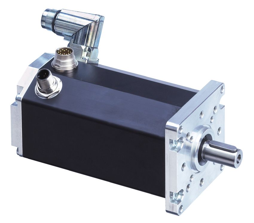
3 General description 3 Allgemeine Beschreibung
Integrierter Inkrementalgeber 2 Motorstecker für Leistungsversorgung und Logik
3.1 Motor range BG 75 PI 3.1 Motorbaureihe BG 75 PI
encoder integrated 2 Motor connectors for power and logic supplies
The motors of the BG 75 PI series are brushless DC Bei der Motorbaureihe BG 75 PI handelt es sich
servomotors with integrated motion controller and um bürstenlose DC-Servomotoren mit integriertem Leistungs- und Steuerungselektronik
comfortable operator interface for PCs on which the Motioncontroller und komfortabler Bedienoberflä- (integriert)
drives can be easily parameterized for a series of che für PC, auf der sich die Antriebe für eine Reihe optional angebaute Bremse
preconfigured basic operating modes. Available as vorgefertigter Grundbetriebsarten leicht parametrie- Power and control electronics
basic operating modes are, for example, a positioning ren lassen. Als Grundbetriebsarten stehen z.B. ein optional attached brake integrated
mode, a speed regulating mode and a torque regula- Positioniermodus, ein Geschwindigkeitsregelmodus
ting mode. These operating modes can be parameteri- und ein Drehmomentregelmodus zur Verfügung. Di- Motor
zed for a large number of frequently occurring appli- ese Betriebsmodi lassen sich für eine Vielzahl häufig
cations. For the controlling of the drives, five digital vorkommender Anwendungen parametrieren. Für die
inputs and two digital feedback outputs are available. Ansteuerung der Antriebe stehen 5 Digitaleingänge
Of these, two digital inputs can also be configured und 2 digitale Meldeausgänge zur Verfügung. Dabei
as analogue inputs so that, for example, speed or können 2 Digitaleingänge auch als Analogeingang Parametrierschnittstelle
current limitation can take place via a potentiometer. konfiguriert werden, so daß z.B. Geschwindigkeits-
By means of the integrated incremental encoder with oder Strombegrenzung über ein Potentiometer erfol- Parametrization interfacae
a resolution 4096 (4x 1024) increments per revoluti- gen kann. Durch den integrierten Inkrementalgeber
Antriebswelle,
on, a very high positioning accuracy with very good mit einer Auflösung von 4096 (4x 1024) Inkrementen optional angebautes Getriebe
regulating characteristics can be achieved. In the pro Umdrehung werden eine hohe Positioniergenau-
positioning mode, for example, a movement of 180° igkeit und sehr gute Regeleigenschaften erreicht. Im Hallsensoren (integriert) output shaft,
can be parameterized whereby the movement can Positioniermodus lässt sich z.B. eine Bewegung um optional attached gearbox
optionally always be in the same rotational direction or 180° parametrieren, wobei die Fahrbewegung wahl- Hall sensors integrated
also alternating in forwards and backwards directions. weise immer in die gleiche Drehrichtung oder auch im
In the positioning mode, various different positions can Wechsel vor- und zurück ausführen lässt. Insgesamt
be parameterized and driven to one after the other. können im Positioniermodus mehrere verschiedene
In addition to the parameterizing of the individual Positionen parametriert und nacheinander ange-
motor functions (position, speed, acceleration, current, fahren werden. Neben der Parametrierung der indivi-
etc.), a large number of the highly varying movement duellen Motorfunktionen (Position, Geschwindigkeit,
sequences can be implemented. Typical applications Beschleunigung, Strom usw.) können eine Vielzahl
are rotary indexing tables, tool changers, eccentric der unterschiedlichsten Bewegungsabläufe realisiert
drives, etc. In the speed regulation mode, various werden. Typische Anwendungen hierfür sind Rund-
different speeds can be stored and selected via the schalttische, Werkzeugwechsler, Exzenterantriebe,
digital inputs. usw. Im Geschwindigkeitsregelmodus lassen sich
mehrere verschiedene Geschwindigkeiten speichern
und über die Digitaleingänge auswählen.
Except for ball bearings, these motors have no parts Der Motor hat außer den Kugellagern keine Ver-
that are subject to wear and are therefore ideally schleißteile und eignet sich deshalb hervorragend
suited to continuous operation. Further significant auch für Dauerbetrieb. Weitere wesentliche Vorteile
advantages of these drives are their highly dynamic des Antriebs liegen in seiner hohen Dynamik, der
performance, their compact design, their wide regu- kompakten Bauweise, dem großen Regelbereich,
lation range, their low moment of inertia, and robust dem geringen Trägheitsmoment und des robusten
construction. Aufbaus.
On request, motors in the BG 75 PI range can be com- Die Motoren BG 75 PI können auf Wunsch auch mit
bined with planetary or worm gears, which are availa- Planeten-, oder Schneckengetrieben mit einer Vielzahl
ble in a very wide range of reduction ratios. fein abgestimmter Untersetzungen kombiniert werden.
Instruction Manual/Betriebsanleitung BG 75 PI, Version: 1.2 en_de Instruction Manual/Betriebsanleitung BG 75 PI, Version: 1.2 en_de
© 2009 Alcatel-Lucent; Dunkermotoren; D-79848 Bonndorf; Germany © 2009 Alcatel-Lucent; Dunkermotoren; D-79848 Bonndorf; Germany3 General description 3 General description
3 Allgemeine Beschreibung 3 Allgemeine Beschreibung
3.2 Explanations of terms used 3.2 Begriffserklärungen 3.3 Proper use 3.3 Bestimmungsmäßige
Verwendung
Component for the transfor- Bauteil zur Umwandlung von
Brückengleichrich- - The BG 75 PI is a vendor part and may be used - Der BG 75 PI ist ein Zulieferteil und darf in der
Bridge rectifier mation from AC voltage to DC Wechselspannung in Gleich-
ter in the configuration described in machines and plant beschriebenen Konfiguration in Maschinen und
voltage spannung
(industrial sector). Anlagen eingesetzt werden (industrieller Bereich).
Default settings Preset values Defaultwerte Voreingestellte Werte - The drive must be securely mounted and must only - Der Antrieb muss fest montiert werden und darf nur
Graphic interface for commis- Grafische Oberfläche zur Inbe- be used with the cables and accessories specified mit den von Dunkermotoren spezifizierten Kabeln
Drive Assistant Drive Assistant by Dunkermotoren. und Zubehörteilen eingesetzt werden.
sioning and parameterisation triebnahme und Parametrierung
- The drive may only be put into service after the - Der Antrieb darf erst nach EMV-gerechter Montage
Smoothing capa- Component to smooth the Glättungskonden- Bauteil zur Glättung von complete system has been installed with due des Gesamtsystems in Betrieb genommen werden.
citor fluctuation voltage sator Spannungsschwankungen attention to EMC aspects.
Sensors for determining the Sensor zur Positionsbestim-
Hall sensors Hallsensoren
position of a rotor mung des Rotors
Revernzierverfahren zur in-
Reference procedure for the
itialen Bestimmung der Po-
Homing initial regulation of the drive Homing
sition des Antriebs in einem
position in the system
System
Digital position indicator. An in- Digitaler Lagegeber. Eine in-
ternal logic processes a signal terne Logik erzeugt aus dem
Incremental
from photodiodes to produce Inkrementalgeber Signal von Fotodioden zwei
encoder
two square-wave signals with um 90° verschobene Recht-
a phase difference of 90°. ecksignale.
The motor voltage is distribu- Die Motorspannung wird
Commutation ted in blocks by an electronic Kommutierung durch eine Elektronik block-
controller weise weitergeschaltet
Position mode Regulation of position Position Mode Lageregelung
Einstellungen zum Beschleu-
Settings to accelerate and
Ramps Rampen nigen und Bremsen des An-
brake the drive
triebs
Fast speed regulation as a Schnelle Drehzahlregelung
subordinate speed controller als untergelagerter Drehzahl-
SVEL Mode for a higher-level positioning SVEL Mode regler für übergeordnete Po-
system sitioniersysteme
(e.g. a CNC-control system). (z.B. CNC-Steuerungen).
Torque regulation, also referred Auch “Current Mode”, Dreh-
Torque mode Torque Mode
to as “Current Mode” momentregelung
Trajectory Sequence of motions Trajektorie Bewegungsablauf
Velocity mode Speed regulation Velocity Mode Drehzahlregelung
Instruction Manual/Betriebsanleitung BG 75 PI, Version: 1.2 en_de Instruction Manual/Betriebsanleitung BG 75 PI, Version: 1.2 en_de
© 2009 Alcatel-Lucent; Dunkermotoren; D-79848 Bonndorf; Germany © 2009 Alcatel-Lucent; Dunkermotoren; D-79848 Bonndorf; Germany4 Safety instructions 5 Technical data, accessories
4 Sicherheitshinweise 5 Technische Daten, Zubehör
4 Safety instructions 4 Sicherheitshinweise 5 Technical data, accessories 5 Technische Daten, Zubehör
Warning! Achtung: 5.1 Electrical data 5.1 Elektrische Daten
Before commissioning, Vor der Inbetriebnahme
the following safety in- sind unbedingt die nach- Permissible Zulässiger
0...5000 rpm 0...5000 rpm
structions must, without folgen Sicherheitshinweise speed range Drehzahlbereich
fail, be read, understood zu lesen und zu beachten!
and observed! Failure to Eine Nichtbeachtung kann Permissible motor voltage 10...50 VDC Zulässige Motorspannung 10...50 VDC
follow them can result in zu Gefahren bei Personen Low-voltage cut-off Unterspannungs-
danger to persons or da- oder Beschädigungen an < 10 VDC < 10 VDC
motor abschaltung Motor
mage to the machine. der Maschine führen!
Permissible control voltage 24 VDC +/- 20% Zulässige Steuerspannung 24 VDC +/- 20%
To ensure trouble-free operation, appropriate methods Der störungsfreie Betrieb setzt entsprechenden Trans- Low-voltage cut-off Unterspannungs-
< 18 VDC < 18 VDC
of transport and conditions of storage must be employed. port und Lagerung nach den entsprechenden Vorga- logic abschaltung Logik
Please store the module so that it is protected from ben voraus: Lagern Sie bitte das Modul geschützt vor
Permissible ripple Max. 5% Zulässige Restwelligkeit Max. 5%
dust, dirt, and moisture. Take care that storage condi- Staub, Schmutz und Feuchtigkeit. Achten Sie darauf,
tions are within the specified limits for storage tem- das die Lagerungsbedingungen nicht außerhalb der Fuse required externally Absicherung extern erforderlich
perature and humidity (see „Technical Data“). Please Lagerungstemperatur bzw. Luftfeuchtigkeit liegt (siehe
transport the module under storage conditions with „Technische Daten“). Transportieren Sie die Module > 115°C temperature > 115°C Temperatur
additional protection against shocks and jolts. bitte unter Lagerungsbedingungen, zusätzlich noch Over-temperature cut-off of output stage PCB Übertemperaturabschaltung der Endstufen-
stoßgeschützt. Leiterplatte
Max. peak current in Max. Spitzenstrom im
Follow the instructions for installation and adjustment Befolgen Sie die Anleitung für den Aufbau und die 50 A (2 sec. at 30°) 50 A (2 sek. bei 30°)
intermediate circuit Zwischenkreis
precisely. To ensure trouble-free operation, please Einrichtung genau. Um einen störungsfreien Betrieb
choose a location for the drive at which the ambient zu ermöglichen, wählen Sie bitte einen Montage-Ort, Current draw of 24V logic Stromaufnahme der
70 mA + DOs 70 mA + DOs
conditions will remain within the permitted limits. For der keine Umweltbedingungen aufweist, die außer- supply 24V-Logikversorgung
precise figures, please see our product description halb der zulässigen Werte liegen. Die genauen Werte
(see „Technical Data“). Installation and dismantling entnehmen Sie bitte der Produktbeschreibung (siehe 5.2 Mechanical data 5.2 Mechanische Daten
must only be carried out with the unit disconnected Technische Daten). Die Montage/Demontage darf nur
from the electrical power supply. The module must im spannungslosen Zustand erfolgen. Die Module dür-
only be installed and adjusted by qualified persons fen nur von qualifiziertem Personal nach den entspre- -20°C...+100°C -20°C...+100°C
Temperature range of motor Temperaturbereich Motor
in accordance with the relevant standards. Qualified chenden Normen eingebaut und eingerichtet werden. housing temperature Gehäusetemperatur
persons are those who: Als qualifiziert gilt eine Person dann, Recommended ambient Empfohlener Umge-
0°C...50°C 0°C...50°C
temperature range bungstemperaturbereich
• on the basis of their experience, can recognise and • wenn sie aufgrund ihrer Erfahrung mögliche
avoid potential dangers; Gefahren erkennen und vermeiden kann, Relative humidity Relative Luftfeuchtigkeit
Max. 90 % Max. 90 %
• are familiar with the accident-prevention regulations • wenn ihr die Unfallverhütungsvorschriften für die (non-condensing) (nicht kondensierend)
for the equipment employed; eingesetzten Geräte bekannt sind IP50 (in special IP50 (in Sonderaus-
and und Degree of protection *) Schutzart *)
versions, up to IP65) führung bis IP65)
• are able to connect circuits and install equipment in • wenn sie gemäß den Normen Stromkreise und
accordance with the standards and regulations. Geräte in Betrieb setzen und installieren darf. Round plug to DIN Rundstecker nach
Connector plug 12-pin Anschlußstecker
45326, Amphenol, DIN 45326,
(logic) 12-polig (Logik)
The equipment must only be taken into service by Die Anlage darf nur durch qualifiziertes oder entspre- C091 Fa. Amphenol, C091
qualified or appropriately trained persons. Qualified chend geschultes Personal in Betrieb genommen Connector plug 4-pin Round plug M17, Anschlußstecker 4-polig Rundstecker M17
persons are familiar with the relevant standards, rules, werden. Qualifizierten Personen sind die gängigen (power stage) Intercontec (Leistung) Fa. Intercontec
and accident-prevention regulations which must be ob- Normen, Bestimmungen und Unfallverhütungsvor-
served when working with such equipment. Please ob- schriften, die bei Arbeiten am Gerät beachtet werden Round plug M12, Rundstecker M12,
Connector plug 5-pin Anschlußstecker 5-polig
serve any regional standards and regulations that apply müssen, bekannt. Bitte beachten Sie die regionalen Binder, Series 763 Fa. Binder, Serie 763
(parametrization interface) (Parametrierschnittstelle)
in the area where the components are used. Please Normen im Einsatzgebiet der Komponenten. Beach- Art.No. 09-3443-00-05 Art.Nr. 09-3443-00-05
also observe the safety instructions that apply to the ten Sie bitte auch die Sicherheitshinweise der zu
equipment or machinery that is to be controlled. So as steuernden Geräte und Maschinen. Um Gefahren *) The degree of protection quoted refers only to the *) Die angegebene Schutzart bezieht sich nur auf das
to be able to avert hazards, make sure that there is a abwenden zu können, vergewissern Sie sich, daß housing of motor or gearbox. Shaft sealing must be Motor- bzw. Getriebegehäuse. Die Abdichtung der Welle ist
serviceable EMERGENCY-STOP switch in immediate ein funktionstüchtiger NOT-AUS-Schalter in direkter provided by the customer. Only when the shaft seals vom Kunden vorzunehmen. Nur wenn der Wellenaustritt
reach and that there is unrestricted access to it. Reichweite mit unbehindertem Zugang liegt. provide adequate protection against dust and water staub- und wassergeschützt montiert wird, kann der Antrieb
can the drive be used in an environment which calls for in einer Umgebung entsprechend IP65 eingesetzt werden.
IP65.
10 Instruction Manual/Betriebsanleitung BG 75 PI, Version: 1.2 en_de Instruction Manual/Betriebsanleitung BG 75 PI, Version: 1.2 en_de 11
© 2009 Alcatel-Lucent; Dunkermotoren; D-79848 Bonndorf; Germany © 2009 Alcatel-Lucent; Dunkermotoren; D-79848 Bonndorf; Germany5 Technical data, accessories 5 Technical data, accessories
5 Technische Daten, Zubehör 5 Technische Daten, Zubehör
5.3 Motor installation drawing 5.3 Motormaßzeichnung 5.5 Motor BG 75x50 PI 5.5 Motor BG 75x50 PI
Nominal voltage 24 V 40 V Nennspannung 24 V 40 V
Nominal power 330 W Nennleistung 330 W
Nominal torque 90 Ncm Nenndrehmoment 90 Ncm
Nominal speed 3500 rpm Nenndrehzahl 3500 rpm
Pulses Geberimpulse
4x1024 (4096) 4x1024 (4096)
per round pro Umdrehung
Nominal current 16.8 A 10.1 A Nennstrom 16.8 A 10.1 A
Demagnetization current 66 A 40 A Entmagnetisierstrom 66 A 40 A
Weight ca. 2500 g Gewicht ca. 2500 g
5.6 Motor BG 75x75 PI 5.6 Motor BG 75x75 PI
Nominal voltage 40 V Nennspannung 40 V
Nominal power 440 W Nennleistung 440 W
Nominal torque 120 Ncm Nenndrehmoment 120 Ncm
Nominal speed 3500 rpm Nenndrehzahl 3500 rpm
Pulses Geberimpulse
4x1024 (4096) 4x1024 (4096)
5.4 Motor BG 75x25 PI 5.4 Motor BG 75x25 PI per round pro Umdrehung
Nominal current 12.9 A Nennstrom 12.9 A
Nominal voltage 24 V 40 V Nennspannung 24 V 40 V Demagnetization current 52 A Entmagnetisierstrom 52 A
Nominal power 220 W Nennleistung 220 W Weight ca. 3200 g Gewicht ca. 3200 g
Nominal torque 60 Ncm Nenndrehmoment 60 Ncm
Nominal speed 3500 rpm Nenndrehzahl 3500 rpm
*) The nominal torque depends on how the motor is *) Das Nenndrehmoment ist abhängig von der Wär-
Pulses Geberimpulse cooled. For this reason, the nominal torque is quoted meabführung des Motors. Deshalb sind die Nenndreh-
4x1024 (4096) 4x1024 (4096)
per round pro Umdrehung to VDE/EN and also measured with a thermally-con- momente gemessen nach VDE/EN sowie gemessen
Nominal current 11.7 A 7.0 A Nennstrom 11.7 A 7.0 A ducting steel plate with the dimensions 105 x 105 x 10 bei Anbringung einer thermisch leitenden Stahlplatte
Demagnetization current 48 A 28 A Entmagnetisierstrom 48 A 28 A mm attached to the motor. der Größe 105 x 105 x 10 mm aufgeführt.
Weight ca. 1900 g Gewicht ca. 1900 g
12 Instruction Manual/Betriebsanleitung BG 75 PI, Version: 1.2 en_de Instruction Manual/Betriebsanleitung BG 75 PI, Version: 1.2 en_de 13
© 2009 Alcatel-Lucent; Dunkermotoren; D-79848 Bonndorf; Germany © 2009 Alcatel-Lucent; Dunkermotoren; D-79848 Bonndorf; Germany5 Technical data, accessories 5 Technical data, accessories
5 Technische Daten, Zubehör 5 Technische Daten, Zubehör
5.7 Optional attachments 5.7 Optionale Anbauten 5.8 Accessories 5.8 Zubehör
Worm gear (SG) Schneckengetriebe (SG) Starter Kit Starterkit
The worm gears are extremely quiet running. In many Die Schneckengetriebe zeichnen sich durch hohe To control a motor using a PC, a starter kit is required. Um einen Motor mit einem PC anzusteuern, benötigt
applications, having the gearbox output shaft at 90° to Laufruhe aus. Bei vielen Anwendungen ist die um 90° This provides an interface between the PC and the mo- man ein Starterkit. Dieser stellt das Interface vom PC
the motor shaft helps to make optimum use of available gegenüber der Motorwelle versetzte Getriebewelle von tor. It must be connected at a USB port. Further infor- zum Motor dar. Er wird an den USB-Port angeschlos-
space. On request worm gears can be supplied with a baulichen Gegebenheiten her optimal. Auf Anfrage sind mation on this subject is given in the relevant section. sen. Weitere Informationen hierzu erhalten Sie im ent-
hollow output shaft. Schneckengetriebe auch mit Hohlwelle lieferbar. sprechenden Abschnitt.
Reduction ratio 5:1 … 80:1 Untersetzungen 5:1 … 80:1 SNR Starter Kit with software CD 27573 35617 SNR Starterkit mit Software-CD 27573 35617
Continuous output torque Max. 30 Nm Dauerdrehmomente max. 30 Nm Drive Assistant Software Drive Assistant Software
Planetary gears (PLG) Planetengetriebe (PLG) The Drive Assistant is a graphic interface which sim- Der Drive Assistent ist eine grafische Oberfläche, die
plifies commissioning and parametrization of the motor. Ihnen die einfache Inbetriebnahme und Parametrie-
Planetary gears have the highest permissible continuo- Planetengetriebe haben die höchsten zulässigen Dau- Further information on this subject is given in the rele- rung der Antriebe ermöglicht. Weitere Informationen
us torque of all types of gearbox and, at the same time erdrehmomente aller Getriebe bei gleichzeitig sehr vant section of this Manual. hierzu finden Sie im entsprechenden Abschnitt der Be-
are very compact, have low weight, and have excellent kompakter Bauform, geringem Gewicht und ausge- triebsanleitung.
efficiency. zeichnetem Wirkungsgrad.
Reduction ratio 3:1 … 700:1 Untersetzungen 3:1 … 700:1
Continuous output torque Max. 160 Nm Dauerdrehmomente max. 160 Nm
6. Types of operation 6. Betriebsarten
Brakes (E) Bremsen (E)
The graphical user interface (see Section 9) enables Das Graphical User Interface (siehe Abschnitt 9) er-
parameterisation for the following types of operation: möglicht die Parametrierung für folgende Betriebsarten:
Brushless DC motors in the BG range can be fitted with Bürstenlose Gleichstrommotren der Baureihe BG kön-
- Current/torque mode - Current/torque mode
a power-off or a power-on brake as an option. nen optional mit angebauten Ruhe- oder Arbeitsstrom-
- Velocity mode - Velocity mode
bremsen ausgerüstet werden.
- Position mode - Position mode
- SVEL mode - SVEL mode
Absolut encoder (AE) Absolutwertgeber (AE)
For larger projects brushless DC motors in the BG 75 Für größere Projekte können Motoren der Baureihen
range can be fitted with an attached absolut encoder. BG 75 mit angebauten Absolutwertgebern ausgestattet
werden.
14 Instruction Manual/Betriebsanleitung BG 75 PI, Version: 1.2 en_de Instruction Manual/Betriebsanleitung BG 75 PI, Version: 1.2 en_de 15
© 2009 Alcatel-Lucent; Dunkermotoren; D-79848 Bonndorf; Germany © 2009 Alcatel-Lucent; Dunkermotoren; D-79848 Bonndorf; Germany7 Protective functions 7 Protective functions
7 Schutzfunktionen 7 Schutzfunktionen
7. Protective functions 7. Schutzfunktionen 7.4 Motors with additional brake 7.4 Motoren mit zusätzlicher Bremse
The objective of protective functions is to protect the Schutzfunktionen dienen dem Schutz des Motors vor Attention: Achtung:
motor against damages by use outside of the permitted Zerstörung außerhalb des zulässigen Betriebsbe- Using a motor with attached Bei Verwendung eines Motors
operating range. reiches. rotor stop brake, a free-whee- mit angebauter Ankerstopp-
ling diode (e.g. type 1N4004 bremse ist zum Schutz vor
or comparable) to protect Kontaktabbrand und zur
7.1 Ballast circuit 7.1 Ballastschaltung against high wear of contact Vermeidung energiereicher
material and to avoid energy Spannungsspitzen eine Frei-
During braking operations, kinetic energy is stored as Bei Bremsvorgängen wird die kinetische Energie als elek- intense voltage peaks must laufdiode (z.B. Typ 1N4004
electrical energy in an intermediate part of the regu- trische Energie in den Zwischenkreis des Regelkreises be installed! oder vergleichbare) einzuset-
lation circuit. This can cause excessive voltage in the zurückgeführt. Dabei kann es im Zwischenkreis zu Span- zen!
intermediate circuit, which, in an extreme case, could nungsüberhöhungen kommen, die im Extremfall Schäden
cause damage to electrical components. To prevent an elektrischen Bauteilen verursachen können. Um dies Assemble the recovery diode according to following Die Freilaufdiode ist gemäß nachfolgender Skizze
this, a DC-power supply should be used which has a zu vermeiden, sollten DC-Netzteile mit Brückengleich- drawing: einzubauen:
bridge rectifier and a smoothing capacitor of at least richter und einem Glättungskondensator von mindestens
1000 µF per 1 A nominal motor current. In addition, an 1000µF pro 1A Motornennstrom verwendet werden. Zu-
Abbildung 4
external ballast resistor (drop resistor) is neccessary. sätzlich ist ein externer Ballastwiderstand notwendig. Der Figure 4
The ballast resistor has to be defined depending on the Ballastwiderstand muss in Abhängikeit der Bremsleistung
braking power. Dunkermotoren recommends a resistor definiert werden. Dunkermotoren empfiehlt einen Wider-
> 2,2 Ω respectively a resistor according to the braking stand > 2,2 Ω bzw. einen Widerstand entsprechend der
power expected (at least 50 watts). zu erwartenden Bremsleistung (mind. 50 Watt).
According to standard, Dunkermotoren offers the bal- Dunkermotoren bietet den Ballastwiderstand Stan-
last resistor (must be ordered seperately). dardmäßig an (muss separat bestellt werden).
SNR 41197.57200 SNR 41197.57200
Abbildung 5:
7.2 Over-temperature protection 7.2 Übertemperaturschutz Figure 5:
To protect the motor against overloading, a temperature Zum Schutz des Motors bei Überlastung ist ein Tempe-
sensor is built into the electronic output stage, which mea- raturmeßfühler in der elektronischen Endstufe integriert,
sures the temperature of the printed circuit board (PCB) welcher die Temperatur der Leiterplatte mißt und den
and switches the controller off at approx. 110 °C. To Regler bei 110°C abschaltet. Um den Antrieb nach dem
return the drive to service after the over-temperature Abschalten wieder in Betrieb zu nehmen, muß der Fehler
cut-off, the error must be acknowledged either by swit- entweder durch schalten der digitalen Eingänge in den
ching the digital inputs in the mode „stop with free- Modus „Stop mit Freilauf“ oder durch kurzzeitiges trennen
wheel“ or must be short-time disconnected from the der Logikspannungsversorgung quittiert werden.
logic power supply.
7.3 Current limitation 7.3 Strombegrenzung
To protect the motor against overloading, the motor Um den Motor vor Überlastung zu schützen wird der
current (phase current) will be supervised from a I2t Motorstrom (Phasenstrom) über eine I2t-Schutzfunktion
protective function and will be limited (if necessary). überwacht und gegebenenfalls begrenzt.
16 Instruction Manual/Betriebsanleitung BG 75 PI, Version: 1.2 en_de Instruction Manual/Betriebsanleitung BG 75 PI, Version: 1.2 en_de 17
© 2009 Alcatel-Lucent; Dunkermotoren; D-79848 Bonndorf; Germany © 2009 Alcatel-Lucent; Dunkermotoren; D-79848 Bonndorf; Germany8 Installation / terminal assignment 8 Installation / terminal assignment
8 Installation / Anschlussbelegung 8 Installation / Anschlussbelegung
8. Installation/ terminal assignment 8. Installation/ Anschlussbelegung 8.3 Protective earth connection 8.3 Schutzleiter Anschluss
Warning! Achtung To protect the drive against damage Zum Schutz des Antriebs vor Be-
Before installation, it is essential that Vor der Installation sind unbedingt or destruction by static discharge schädigung oder Zerstörung durch
the safety instructions in the relevant die Sicherheitshinweise zu lesen und (ESD), the motor housing must be statische Entladung (ESD) muß das
section are read and understood, and zu beachten! Gerät spannungsfrei earthed. Motorgehäuse geerdet werden. Nach
then observed! Disconnect the electri- schalten! As far as possible, the drive should Möglichkeit sollten die Antriebe nur
cal power supply! only be handled by persons wearing von Personen mit ESD-Schutzausrü-
ESD-protective clothing. stung angefaßt werden.
• The motor housing must be connected to the machine • Das Motorgehäuse muß mit einem separaten Schutzleiter-
Attention Vorsicht earth by a separate earth lead. kabel mit der Maschinenmasse verbunden werden.
It is important to use two separate Die Motorspannungsversorgung und die • This cable must be connected to the flange with a screw. • Hierzu wird das Kabel mit einer Schraube im Flansch
power supply units, one for the po- Elektronikversorgung (+24V) benöti- • Please avoid touching the connector pins. befestigt.
wer of the motor and one for the gen 2 separate Netzteile, die eine ge- • Bitte die Steckerpins nicht berühren
electronic (+24V). Both power units meinsame Masse (-0V) haben.
have a common earth (-0). Beim aktiven Bremsen werden Span-
In case of active braking additional nungen/ Ströme erzeugt, die in die im
voltage/ current will be generated. Motor integrierte Elektronik zurückge- 8.4 Motor power supply 8.4 Leistungsversorgung Motor
The integrated electronic could be speist werden und diese zerstören
destroyed. können.
Plug: Stecker:
Round plug, Intercontec Rundstecker, Fa. Intercontec
8.1 Mechanische Montage The 4pin plug for motor power stage. Der 4-polige Stecker dient zur Leistungsversorgung
8.1 Mechanical assembly
des Motors.
Attention Vorsicht
During installation, ensure that con- Achten Sie bei der Installation darauf,
dass die Steckverbinder nicht beschä- Lead colour Litzen-
nectors are not damaged. Bent pins
digt werden. Umgebogene Pins kön- in connec- farbe der
can cause a short circuit and destroy
nen den Antrieb durch Kurzschluss Con- tion cable Ste- Anschluss-
the drive. Connec- An-
zerstören. nector with 4-pin cker- leitung mit
tion schluß
pin right-angle Pin 4pol. Win-
Prüfen Sie den Antrieb vor der Installation auf äußer- connector kelstecker
Before installation, check the drive externally for visible
lich sichtbare Beschädigungen. Bauen Sie beschädigte (*) (*)
signs of damage. Do not install a damaged drive. The
drive must be secured with at least 4 threaded fasten- Antriebe nicht ein. Der Antrieb muss mit mindestens 4 + (motor + (motor
1 black 1 schwarz
ers to a flat surface. Screws in the flange must be fitted Schraubverbindungen an einer planen Oberfläche befe- power) power)
with spring washers to prevent them coming loose. The stigt werden. Die Flanschschrauben müssen mit Federr- Ballast Ballast-
radial and axial loads on the motor output shaft must ringen gegen Verdrehen geschützt werden. 2 black
resistor 2 wider- schwarz
not exceed 150 N. For motor-gear units, see the gear- Die Motorabtriebswelle darf mit maximal 150N radial oder stand
P GND
box documentation for relevant data. axial belastet werden. Bei Getriebmotoren sind die ent- 3 black
(0V) P GND
sprechenden Daten der Dokumentation zum Getriebe zu 3 schwarz
Earth (0V)
entnehmen. 4 yellow/green
wire 4 Erdung gelb/grün
8.2 Electro-magnetic compatibility 8.2 Elektromagnetische Verträglichkeit
The BG 75 PI drive and the machine in which it is installed Beim Antrieb BG 75 PI und bei der Maschine, in welche
(*) Lead colours refers to standard connection cables (*) Litzenfarben beziehen sich auf Standard An-
give rise to the radiation of electromagnetic interference. der Antrieb eingebaut wird, entstehen elektromagne-
of Dunkermotoren. schlussleitungen von Dunkermotoren.
Without suitable protective measures, this can influence tische Störstrahlungen. Diese können ohne geeignete
signals in control cables and parts of the installation and Schutzmaßnahmen die Signale von Steuerleitungen und
endanger the operational reliability of the installation. Anlageteilen beeinflussen und die Betriebssicherheit der
Before putting the machine into service, its electroma- Anlage gefährden.
gnetic compatibility must be checked and any necessary Vor dem Betrieb muss die elektromagnetische Verträg-
measures taken. lichkeit der Maschine geprüft und sichergestellt werden.
18 Instruction Manual/Betriebsanleitung BG 75 PI, Version: 1.2 en_de Instruction Manual/Betriebsanleitung BG 75 PI, Version: 1.2 en_de 19
© 2009 Alcatel-Lucent; Dunkermotoren; D-79848 Bonndorf; Germany © 2009 Alcatel-Lucent; Dunkermotoren; D-79848 Bonndorf; Germany8 Installation / terminal assignment 8 Installation / terminal assignment
8 Installation / Anschlussbelegung 8 Installation / Anschlussbelegung
Mating connector with cable (please order in addition) Gegenstecker mit Anschlußleitung (bitte mitbestel- 8.5 Power supply electronic and 8.5 Elektronikversorgung und
For the BG 75 PI motors with 4-pin connector, pre-as- len): Für die Motoren BG 75 PI mit 4-poligem An- signal interface Schnittstellen
sembled connection cables are available in a range of schlußstecker stehen passende, vorkonfektionierte
lengths from stock. On one end these cables have the Anschlußleitungen in verschiedenen Längen ab Lager
appropriate 4-pin right-angle connector already fitted. zur Verfügung. Die Leitungen sind auf einer Seite mit Motor plug Motorstecker:
At the other end the cable is simply cut off. The diame- einer entsprechenden 4-poligen Winkeldose anschluß- Rundstecker nach DIN 45326, Fa. Binder, Serie 723
Round plug to DIN 45326, Binder, Series 723
ter of the cable is 9.5 to 12 mm. fertig konfektioniert. Auf der anderen Seite sind die Lei- Der 12-polige Motorstecker dient zur Spannungsver-
The 12-pin motor connector supplies power for the
tungen glatt abgeschnitten. Die Leitungen haben einen sorgung des Motors und zur Logikversorgung mit 24V
motor and a 24V supply for the control electronics.
Durchmesser von 9,5 bis 12 mm.
für die Regelelektronik.
E F G
The following cable lengths are available: Es sind folgende Leitungslängen lieferbar:
Cable length Leitungslänge
3m 3m M
10m 10m D
H
C
L J
B A K
Con- Lead colour in connection Litzenfarbe der Anschluß-
Connec- Stecker-
nector cable with 12-pin right-angle Anschluß leitung mit 12pol. Winkel-
tion Pin
pin connector (*) stecker (*)
A IN0 yellow A IN0 gelb
B IN1 blue B IN1 blau
C IN2 brown C IN2 braun
D IN3 green D IN3 grün
E OUT1 grey E OUT1 grau
F OUT2 grey-pink F OUT2 grau-rosa
G AI (+) pink G AI (+) rosa
H AI (-) violet H AI (-) violett
Uc (+24V) Uc (+24V)
J red J rot
Logic Logic
GND (0V) GND (0V)
K black K schwarz
Logic Logic
L IN4 red-blue L IN4 rot-blau
M OUT3 white M OUT3 weiß
(*) Lead colours refers to standard connection cables (*) Litzenfarben beziehen sich auf Standard An-
of Dunkermotoren. schlussleitungen von Dunkermotoren.
20 Instruction Manual/Betriebsanleitung BG 75 PI, Version: 1.2 en_de Instruction Manual/Betriebsanleitung BG 75 PI, Version: 1.2 en_de 21
© 2009 Alcatel-Lucent; Dunkermotoren; D-79848 Bonndorf; Germany © 2009 Alcatel-Lucent; Dunkermotoren; D-79848 Bonndorf; Germany8 Installation / terminal assignment 8 Installation / terminal assignment
8 Installation / Anschlussbelegung 8 Installation / Anschlussbelegung
8.6 Schematic circuit of the digital outputs 8.6 Prinzipschaltung der Digitalausgänge 8.8 Parametrization connector 8.8 Parametrierschnittstelle
Output Ausgang Motor plug Motorstecker:
Round plug M12, Binder, Series 763, Rundstecker M12, Fa. Binder, Serie 763,
Chargeable Mit max. Art.No. 09-3443-00-05 Art.Nr. 09-3443-00-05
with max. 250 mA
250 mA. belastbar. 1
5
8.7 Schematic circuit of the digital inputs 8.7 Prinzipschaltung der Digitaleingänge
2 4
3
Mating connector with cable (please order in addition) Gegenstecker mit Anschlußleitung (bitte mitbestellen): Starter Kit Starterkit
For the BG 75 PI motors with 12-pin connector, pre-assem- Für die Motoren BG 75 PI mit 12-poligem Anschlußstecker
bled connection cables are available in a range of lengths stehen passende, vorkonfektionierte Anschlußleitungen To parameterize the motor, a Starter Kit is required Um einen Motor zu parametrieren, benötigt man ein
from stock. On one end these cables have the appropriate in verschiedenen Längen ab Lager zur Verfügung. Die (see also the “Accessories” Section). This provides the Starterkit (siehe auch Abschnitt „Zubehör“). Dieser
12-pin right-angle connector already fitted. At the other end Leitungen sind auf einer Seite mit einer entsprechenden interface from the PC to the motor. It is connected to stellt das Interface vom PC zum Motor dar. Er wird an
the cable is simply cut off. The diameter of the cable is 7.6 12-poligen Winkeldose anschlußfertig konfektioniert. Auf der the USB port and the 5-pole motor plug. den USB-Port und an den 5-poligen Motorstecker an-
mm. anderen Seite sind die Leitungen glatt abgeschnitten. Die geschlossen.
Leitungen haben einen Durchmesser von 7,6 mm.
Cable length Leitungslänge
3m 3m
10m 10m
22 Instruction Manual/Betriebsanleitung BG 75 PI, Version: 1.2 en_de Instruction Manual/Betriebsanleitung BG 75 PI, Version: 1.2 en_de 23
© 2009 Alcatel-Lucent; Dunkermotoren; D-79848 Bonndorf; Germany © 2009 Alcatel-Lucent; Dunkermotoren; D-79848 Bonndorf; Germany9 Connection schematic 9 Connection schematic
9 Anschlussschema 9 Anschlussschema
9 Connection schematic 9 Anschlussschema 9.1 Connection motor power 9.1 Anschluss Leistungsversorgung
supply Motor
Warning! Achtung:
Before commissioning, the safety in- Vor der Inbetriebnahme sind unbe- + (power) 24...(42) V DC
structions must, without fail, be read, dingt die Sicherheitshinweise zu le-
understood and then observed! sen und zu beachten! P GND (0V)
PE
yellow-green
An incorrectly set parameter can, Ein falsch eingestellter Parameter gelb-grün
under some circumstances, result kann unter Umständen zum Schwin-
in oscillation of the controller and gen des Reglers führen und den
destruction of the motor. It is recom- Motor zerstören. Es empfiehlt sich, 4
mended that current limits and con- Stromgrenzen und Reglerparameter, 3 1
black/schwarz
black/schwarz
trol parameters are initially set to low von kleinen Werten beginnend vor-
values and then carefully increased sichtig zu erhöhen.
in small steps. 2
Ballast
It is absolutely important for con- Beim Anschluss der Antriebe ist un-
necting the cables to check the right bedingt die richtige Polarität sowohl
polarity of the power supply to the der Spannungsversorgungen für
motor, bus electronic and the data Motor und Buselektronik sowie der
line. A wrong connection of the po- Datenleitungen zu prüfen. Ein verpo-
wer supply maybe destroy the power len der Spannungsversorgung des
electronic. The motor isn‘t protected Motors kann die Leistungselektronik 9.2 Connection electronic supply and 9.2 Anschluss Elektronikversorgung und
against wrong connection of the po- zerstören! Der Antrieb enthält keinen signal interface Schnittstellen
wer supply. Verpolungsschutz für die Motorspan-
nung.
Signale / Signals (E/A) Versorgung/ Supply:
Eine Nichtbeachtung kann zu Gefahren an Personen
OUT2
OUT3
Failure to follow them can result in danger to persons
OUT1
AI (+)
AI (-)
IN1
IN4
IN0
IN2
IN3
or damage to the machine. oder Beschädigungen an der
Uc (+24 V) Logik / Logic
A B C D E F G H L M J
GND (0V) Logik / Logic
K
grau-rosa
grey-pink
pink/rosa
violet/violett
grey/grau
red-blue
blue/blau
green/grün
rot-blau
yellow/gelb
brown/braun
white/weiß
Lead colours refers to standard connection cables of Litzenfarben beziehen sich auf Standard Anschlusslei-
Dunkermotoren. tungen von Dunkermotoren.
24 Instruction Manual/Betriebsanleitung BG 75 PI, Version: 1.2 en_de Instruction Manual/Betriebsanleitung BG 75 PI, Version: 1.2 en_de 25
© 2009 Alcatel-Lucent; Dunkermotoren; D-79848 Bonndorf; Germany © 2009 Alcatel-Lucent; Dunkermotoren; D-79848 Bonndorf; Germany10 Software Drive Assistant 11 Description of the Main Window
10 Software Drive Assistant 11 Beschreibung des Hauptfensters
10 Software Drive Assistant 10 Software Drive Assistant 11 Description of the Main Window 11 Beschreibung des Hauptfensters
11.1 Description of the General 11.1 Beschreibung der allgemeinen
10.1 Introduction 10.1 Einführung Parameter Groups - Main Window Parametergruppen - Hauptfenster
With the Drive Assistant control program, Dunkermo- Mit dem Steuerungsprogramm Drive Assistant bietet
toren provides a comprehensive software tool with Dunkermotoren ein umfangreiches Softwaretool, mit
which it is possible to extensively configure the vari- dem es möglich wird verschiedene Typen von BG-
ous types of BG motors. Via a parameterising inter- Motoren umfangreich zu konfigurieren. Über eine
face, the software establishes a connection with the Parametrierschnittstelle stellt die Software die Verbin-
motor and programs it with the individual configurati- dung mit den Motoren her und programmiert diesen
on. By means of prepared masks within the software, mit der individuellen Konfiguration. Innerhalb der Soft-
you can program various modes individually with ware kann über vorgefertigte Masken eine individuelle
extensive parameter selection. Programmierung in verschiedenen Modi mit umfang-
reicher Parameterauswahl vorgenommen werden.
10.2 System Requirements 10.2 Systemvoraussetzungen
Operating system: Windows 2000, Windows XP Betriebssystem: Windows 2000, Windows XP Home,
Home, Windows XP Pro, Windows Vista. The installa- Windows XP Pro, Windows Vista. Sie können die In- The following parameter groups are common to all modes: Allen Modi gemeinsam sind folgende Parametergruppen:
tion files for the “Drive Assistant” can either be loaded stallations-Dateien für den „Drive Assistant“ entweder
from the CD-ROM provided or downloaded from the von der mitgelieferten CD-ROM oder von der Dunker-
Dunkermotoren homepage. motoren Homepage herunterladen. Group Field „Projects“ Gruppenfeld „Projects“
In the „Project“ group field, the configurablemo modis Im Gruppenfeld „Projects“ werden die konfigurier-
10.3 Installation of the Software Drive 10.3 Installation der Software Drive are shown. By double click on an elected modi, the baren Modis angezeigt. Durch Doppelklicken auf
Assistant Assistant elected project submission appears in a new window. ein gewähltes Modi, erscheint in neuem Fenster die
gewählte Projektvorlage.
Administrator privileges are necessary for the instal- Zur Installation des Programms benötigen Sie Ad-
la-tion. The installation menu will start automatically min-Rechte. Nach dem Einlegen der CD-Rom öffnet
when you insert the CD-ROM. Alternatively you can sich das Installationsmenü automatisch. Sollte sich
open the file install.htm to open the installation menu. das Menü nicht automatisch öffnen, so öffnen Sie im
The programm will guide you through the installati- Windows-Explorer die sich auf der CD-Rom befin-
on routine. Go ahead with the installation in case a dende Datei install.htm. Sie werden nun durch das
warning notice concerning the USB driver will pop up. Installationsmenü geführt. Klicken Sie auf „Installation
After successful installation the Drive Assistant can be fortsetzen“, falls während der Installation ein Warnhin-
startet by the desktop link. weis bezüglich dem USB-Controller erscheint. Nach
erfolgreicher Installation kann der Drive Assistant über 11.2 Description of the Menu Bar 11.2 Beschreibung der Menüleiste
die Desktop-Verknüpfung geöffnet werden. - Main Window - Hauptfenster
„Program“ Menu „Program“-Menü
With „Options“ the user can change the language of Mit „Options“ kann die Sprache der Hilfetexte geän-
the help text. With „Exit“ the user leaves the program. dert werden. Mit „Exit“ verlässt der Anwender das
Programm.
26 Instruction Manual/Betriebsanleitung BG 75 PI, Version: 1.2 en_de Instruction Manual/Betriebsanleitung BG 75 PI, Version: 1.2 en_de 27
© 2009 Alcatel-Lucent; Dunkermotoren; D-79848 Bonndorf; Germany © 2009 Alcatel-Lucent; Dunkermotoren; D-79848 Bonndorf; GermanyYou can also read