OPERATING MANUALLINEAR AXIS AXE BETRIEBSANWEISUNGLINEARACHSENAXE - NTN SNR
←
→
Page content transcription
If your browser does not render page correctly, please read the page content below
OPERATING MANUALLINEAR AXIS AXE BETRIEBSANWEISUNGLINEARACHSENAXE
Manufacturer / Hersteller
SNR WÄLZLAGER GMBH
Friedrich-Hagemann-Straße 66
D-33719 Bielefeld
Tel.: +49 (0) 521 924 00 112

email: linear@ntn-snr.de

www.ntn-snr.com/documents/linear

                                   2
Table of contents

1.____ System technology................................ E 5                                                    for Linear Axis AXE_Z (except AXE110Z)...............E 20

1.1_______Definitionen............................................................ E 5            2.12.2.___Mounting of inductive proximity switches (groove
                                                                                                             installation) for Linear Axis AXE60Z, AXE80Z
1.2_______Declaration of incorporation for partly completed                                                 and AXE100Z.........................................................E 21
           machinery (Machinery directive 2006/42/EG)......... E 5
                                                                                                  2.12.3.___Mounting of limit switches
1.3_______Safety instructions................................................. E 6                           for Linear Axis AXE110Z and proximity switches for
1.4_______Intended use.......................................................... E 6                         AXE160Z..............................................................E 22
1.5_______Coordinate system................................................. E 6                  2.12.4.___Mounting of limit switches on the drive head
1.6_______Static load capacity................................................ E 7                           of Linear Axis AXE_A with moving profile...............E 23
1.7_______Life time................................................................. E 7          2.12.5.___Mounting of limit switches on the profile
                                                                                                             of Linear Axis AXE_A with moving drive head........E 24
1.7.1._____Dynamic load capacity / nominal life time............... E 7
                                                                                                  2.13______Start-up of Linear Axis..........................................E 25
1.7.2._____Influence factors.................................................... E 7
1.8_______Rigidity................................................................... E 8
1.9_______Dynamic operating load......................................... E 9                     3.____ Maintenance and lubrication.........E 26
1.10______Precision................................................................ E 9           3.1_______General information...............................................E 26
1.11______Gearbox selection.................................................E 10                  3.2_______Lubrication............................................................E 26
1.11.1.___Maximum operation speed...................................E 10                          3.3_______Lubricants.............................................................E 26
1.11.2.___Maximum acceleration torque...............................E 10                          3.4_______Lubrication methods.............................................E 27
1.11.3.___Nominal torque on the drive..................................E 10                       3.4.1._____Manual grease gun...............................................E 27
1.12______Drive calculation....................................................E 11               3.4.2._____Automatic electro-mechanical
1.13______Selection of Linear Axis with toothed belt drive                                                   lubricator DRIVE BOOSTER..................................E 27
           for 90 ° tilt mounting (wall mounting).....................E 11                        3.5_______Lubrication points.................................................E 28
                                                                                                  3.6_______Amounts of lubricant.............................................E 28
2.____ Mounting and start-up.......................E 12                                           3.7_______Lubrication intervals..............................................E 29
                                                                                                  3.8_______Cover strip replacement........................................E 30
2.1_______Transportation and storage...................................E 12
                                                                                                  3.8.1._____Cover strip replacement
2.2_______Design of the mounting surfaces /
                                                                                                              for the Linear Axis AXE110 and AXE160...............E 30
           mounting tolerances.............................................E 12
                                                                                                  3.9_______Wear part sets......................................................E 30
2.3_______Mounting instruction.............................................E 14
2.4_______Mounting of parallel Linear Axis.............................E 15
2.5_______Tightening torques................................................E 15
2.6_______Form-fitted mounting of planetary gearboxes........E 16
2.7_______Force-fitted mounting of couplings........................E 16
2.8_______Mounting of planetary gearboxes via coupling
           and coupling cone................................................E 17
2.9_______Mounting of the gearbox flange.............................E 18
2.10______Drive assembly.....................................................E 19
2.11______Mounting of parallel Linear Axis
           with connecting shaft............................................E 19
2.12______Mounting of limit switches.....................................E 20
2.12.1.___Mounting of limit switches

                                                                                            E 3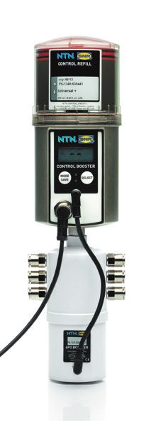
Inhalt
1.____ Systemtechnologie . . . . . . . . . . . . . . D 5                                 2.10_____ Motormontage. . . . . . . . . . . . . . . . . . . . . . . . . . D19
1.1______ Definitionen . . . . . . . . . . . . . . . . . . . . . . . . . . . . D 5       2.11_____ M
                                                                                                    ontage von parallelen Linearachsen mit
                                                                                                   Verbindungswellen. . . . . . . . . . . . . . . . . . . . . . . D19
1.2______ E
           inbauerklärung für eine unvollständige Maschine
          (Machinery directive 2006/42/EG). . . . . . . . . . . . D 5                    2.12_____ Montage von Endschaltern. . . . . . . . . . . . . . . . . D20
1.3______ Sicherheitshinweise . . . . . . . . . . . . . . . . . . . . . . D 6            2.12.1.__ M
                                                                                                    ontage von Endschaltern
                                                                                                   für Linearachsen AXE_Z (außer AXE110Z) . . . . . D20
1.4______ Bestimmungsgemäße Verwendung . . . . . . . . . . D 6
                                                                                         2.12.2.__ M
                                                                                                    ontage von induktiven Schaltern zum Nuteinbau an
1.5______ Koordinatensystem. . . . . . . . . . . . . . . . . . . . . . .D 6
                                                                                                   Linearachsen AXE60Z, AXE80Z und AXE100Z. . . . . . D21
1.6______ Statische Belastbarkeit. . . . . . . . . . . . . . . . . . . . D 7
                                                                                         2.12.3.__ M
                                                                                                    ontage von Endschaltern für Linearachsen
1.7______ Lebensdauer . . . . . . . . . . . . . . . . . . . . . . . . . . . D 7                    AXE110Z und Näherungsschaltern
1.7.1.____ D
            ynamische Belastbarkeit /                                                             für AXE160Z. . . . . . . . . . . . . . . . . . . . . . . . . . . . D22
           nominelle Lebensdauer . . . . . . . . . . . . . . . . . . . D 7               2.12.4.__ M
                                                                                                    ontage von Endschaltern am Antriebskopf von
1.7.2.____ Einflussfaktoren . . . . . . . . . . . . . . . . . . . . . . . . . D 7                  Linearachsen AXE_A mit bewegtem Profil . . . . . D23
1.8______ Steifigkeit. . . . . . . . . . . . . . . . . . . . . . . . . . . . . . D 8     2.12.5.__ M
                                                                                                    ontage von Endschaltern am Profil von
1.9______ Dynamische Betriebslast . . . . . . . . . . . . . . . . . . D 9                          Linearachsen AXE_A
                                                                                                   mit bewegtem Antriebskopfl. . . . . . . . . . . . . . . . D24
1.10_____ Präzision. . . . . . . . . . . . . . . . . . . . . . . . . . . . . . .D 9
                                                                                         2.13_____ Inbetriebnahme von Linearachsen . . . . . . . . . . . D25
1.11_____ Getriebeauswahl. . . . . . . . . . . . . . . . . . . . . . . . D10
1.11.1.__ Maximale Betriebsdrehzahl. . . . . . . . . . . . . . . . . D10
1.11.2.__ Maximales Beschleunigungsmoment. . . . . . . . . D10                           3.____ Wartung und Schmierung. . . . . . . D26
1.11.3.__ Nenndrehmoment am Antrieb . . . . . . . . . . . . . . D10                      3.1______ Allgemeine Informationen. . . . . . . . . . . . . . . . . . D26
1.12_____ Antriebsauslegung. . . . . . . . . . . . . . . . . . . . . . . D11             3.2______ Schmierung. . . . . . . . . . . . . . . . . . . . . . . . . . . . D26
1.13_____ A
           uswahl von Linearachsen                                                      3.3______ Schmierstoffe. . . . . . . . . . . . . . . . . . . . . . . . . . . D26
          mit Zahnriemenantrieb für um 90° gekippte                                      3.4______ Schmiermethoden. . . . . . . . . . . . . . . . . . . . . . . D27
          Montage (Wandmontage). . . . . . . . . . . . . . . . . . D11                   3.4.1.____ Fettpressen . . . . . . . . . . . . . . . . . . . . . . . . . . . . D27
                                                                                         3.4.2.____ Zentralschmierungen. . . . . . . . . . . . . . . . . . . . . D27
2.____ Montage und Inbetriebnahme. . D12                                                 3.5______ Schmierstellen. . . . . . . . . . . . . . . . . . . . . . . . . . D28
2.1______ Transport und Lagerung. . . . . . . . . . . . . . . . . . . D12                3.6______ Schmiermengen. . . . . . . . . . . . . . . . . . . . . . . . . D28
2.2______ G
           estaltung Montageflächen /                                                   3.7______ Schmierintervalle . . . . . . . . . . . . . . . . . . . . . . . . D29
          Montagetoleranzen. . . . . . . . . . . . . . . . . . . . . . . D12             3.8______ Austausch Abdeckband. . . . . . . . . . . . . . . . . . . D30
2.3______ Montageanleitung. . . . . . . . . . . . . . . . . . . . . . . . D14            3.8.1.____ A
                                                                                                     ustausch Abdeckband
2.4______ Montage von parallelen Linearachsen. . . . . . . . . D15                                  bei Linearachsen AXE110 und AXE160 . . . . . . . D30
2.5______ Anzugsmomente . . . . . . . . . . . . . . . . . . . . . . . . D16              3.9______ Verschleißteil - Sets . . . . . . . . . . . . . . . . . . . . . . D30
2.6______ F
           ormschlüssige Montage
          von Planetengetrieben. . . . . . . . . . . . . . . . . . . . D16
2.7______ Kraftschlüssige Montage von Kupplungen. . . . . D16
2.8______ M
           ontage von Planetengetrieben über Kupplung
          und Kupplungsglocke. . . . . . . . . . . . . . . . . . . . . D17
2.9______ Montage Getriebeflansch. . . . . . . . . . . . . . . . . . D18

                                                                                       D 4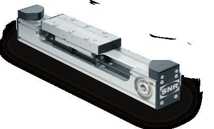
1.         System technology
1.1        Definition
Linear Axis are pre-finished units with a combination of precise guiding and driving elements. Thereby Linear Axis with their variations
are cost efficient and extremely compact components for machines and systems which could be mounted and placed into operation
within a short time.

The selection of Linear Axis could be based on following criteria:

POSITIONING                 When positioning repeatability, an arbitrary point is approached several times in one direction from the
REPEATABILITY               same starting point and the deviation to the target value can be measured. The process is repeated
                            for different points. ± 50% of the difference between maximum and minimum deviation is given as
                            positioning repeatability.
POSITION ACCURACY When measuring the positioning accuracy several points are approached in one direction and the
                            difference between target travel distance and actual travelled distance measured. The position accuracy
                            is the absolute maximum difference.

RUNNING                     The dial gauge is centrally mounted on the carriage and moved over the complete stroke. The running
PARALLELISM                 parallelism is the maximum difference between the measured values.

For the selection of SNR Linear Axis are also our sales and application engineers with years of experience available.

1.2        Declaration of incorporation for partly completed machinery (Machinery directive 2006/42/EG)
The manufacturer SNR WAELZLAGER GMBH, Friedrich-Hagemann-Straße 66, D-33719 Bielefeld, Germany hereby declares that
the components of the partly completed machinery from the series “Linear Axis AXE”:

           • Following essential health and safety requirements in accordance to Annex I of machinery directive 2006/42/EG are
             applied and fulfilled:
                                              General principles:
                                              1.1 General remarks
                                              1.3 Protection against mechanical hazards
                                              1.5. Risks due to other hazard
                                              1.6. Maintenance
                                              1.7. Information

           • The relevant technical documentations are compiled in accordance with part B of Annex VII
           • We will transmit in case of a reasoned request by the national authorities the relevant technical documentation in
              accordance with part B of Annex VII.
           • He above mentioned relevant technical documentations can be obtained from QC Department, SNR WAELZLAGER
             GMBH, Friedrich-Hagemann-Straße 66, D-33719 Bielefeld, Germany
           • The conformity is in accordance with the EN ISO 12100: 2010 «Safety of machinery - General principles for design - Risk
             assessment and risk reduction «
           • The partly completed machinery must not be put into service, until the final machinery, into which it is to be incorporated,
             has been declared in conformity with the provisions of machinery directive 2006/42/EG if required.

                                              i.V. Ulrich Gimpel
                                              (Industry Engineering Division Head)
                                              SNR WÄLZLAGER GMBH - Friedrich-Hagemann-Straße 66 D-33719 Bielefeld, Germany
                                              Bielefeld, December 2019

                                                                E 5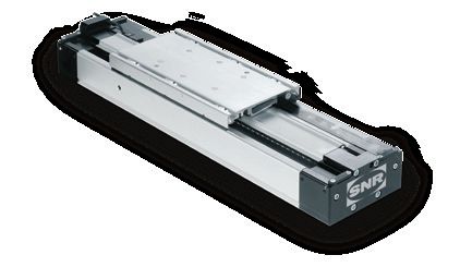
1.3         Safety instructions

                 The device is built according to current state-of-
                 the-art technology and applicable regulations. The         In addition, operating equipment poses a risk of injury due to rotating or
                 device complies with the EU machinery directive,           otherwise moving components. Due to moving carriages, operational
                 harmonized standards, European standards or the            Linear Axis particularly poses an increased crushing hazard, especially
                 applicable national standards. This is confirmed with      in connection with end position dampers and limit switches. The user
a manufacturer’s declaration.                                               must make these residual risks known with signs or written codes
                                                                            of conduct. Alternative, the user can eliminate or exclude these
Relevant accident prevention regulations, generally accepted safety-        residual risks to the greatest extent possible by employing appropriate
related rules, EU guidelines, other applicable standards and country-       constructive measures.
specific regulations are also applicable.

Because linear units can be used in such a wide range of applications,      The noise level can increase at high speeds, special applications
the ultimate responsibility and liability for appropriate use lies with     and at accumulation of more noise sources. The user must take the
the end user.                                                               appropriate protective measures.

This device creates an unavoidable residual risk for personal injury        Linear Axis start-up is prohibited until it can be established that the
and material damage. For this reason, every individual who works            machine or system in which it is mounted conforms to EU machinery
on this device associated with the transport, assembly, operating,          directives, harmonized standards, European standards or applicable
maintenance and repair of the device, must receive instruction and          national standards.
understand the potential dangers. The information about mounting,
start-up, maintenance and lubrication must be understood and
observed.

1.4         Intended use
SNR Linear Axis are fundamentally designated for linear movement            The manufacturer assumes no liability for resulting damages. The
as occurs during positioning, synchronization, transport, palletizing,      user bears sole responsibility for all risks.
loading, unloading, clamping, tightening, testing, measuring,
handling and manipulating components or tools. Type-specific load           The Linear Axis may only be operated and serviced by individuals
data from the relevant catalogue documentation and/or NTN-SNR               familiar with the axis and who have been instructed in the dangers.
supplementary technical calculations must be observed.
                                                                            In special applications (such as food industry, clean room etc.),
Furthermore, an operating temperature between –10°C to +80°C                special precautions must be taken by the user which deviate from
must be adhered to.                                                         the standard version.
Alternative or excessive use is considered improper use.

1.5         Coordinate system
The Linear Axis can be stressed by forces or torques.
The coordinate system (Figure 2.1) shows the forces acting in
the main load directions, the torques as well as the six degrees
of freedom.

            Forces in the main load directions:
            FX Movement force (X direction)
            FY Tangential load (Y direction)
            FZ Radial load (Z direction)

            Moments:
            MX Torque in roll direction (rotation around the
            X axis)
            MY Torque in pitch direction (rotation around the Y axis)
            MZ Torque in yaw direction (rotation around the Z axis)

                                                                                             Figure 2.1____ Coordinate system

                                                                          E 6
1.6                                 Static load capacity
The values of the static load capacity given in the data tables of the                                          If a Linear Axis is subjected in static alternating loads use, the values
Linear Axis represent the maximum load that can be applied.                                                     of the dynamic load capacity shall be recognized as the maximum
                                                                                                                values in this case.
The loads (radial and tangential) and moments can act simultaneously
from different directions on the Linear Axis (Figure 2.2).

In this case, a maximum equivalent load, this consists of radial,
tangential and other loads, used for verification. For this, the position
must be located within the movement cycle in which the interaction                                                                            FE                   FZ
all loads has the maximum value.
For complex loads, we recommend to contact our NTN-SNR
applications engineers.
A minimum safety factor for static load capacity is not given here.                                                                                                              FY
The static load capacity may not be confused with the static load rating
that is specified in calculation of linear guides.

The static load capacity of a Linear Axis results from the maximum
load capacity of all related components in their interaction and is less
than the static load rating of the guiding system.
An additional check the static safety of the guiding system is not                                              Figure 2.2____ Equivalent load
necessary.

1.7                                 Life time
1.7.1.                              Dynamic load capacity / nominal life time
The catalogue data of the dynamic load capacity of the Linear Axis                                              If the nominal life time of the Linear Axis should be calculated,
AXE are based on the nominal life time of 50.000 km.                                                            the calculation basics for linear guides which are described in the
The change of the nominal lifetime depending on the load is shown                                               relevant catalogue must be applied.
in Figure 2.3.
If the loads are lower than the described limits, no further investigation
is necessary.

                          100 000                                                                                                                            inear Axis with toothed
                                                                                                                                                            L
                           90 000                                                                                                                           belt drive
                           80 000
                           70 000
 Nominal life time [km]

                           60 000
                           50 000
                           40 000
                           30 000
                           20 000
                           10 000
                               0
                                    50   60     70      80     90     100     110     120   130   140    150   160   170   180   190   200

                                          Load in relation to dynamic load capacity [%]

Figure 2.3____ Nominal life time

In case of higher dynamic loads, please contact at on our NTN-SNR application engineers or use for complex loads our calculation
service.

1.7.2.                              Influence factors
For a calculation of the nominal life, it is often very difficult, to determine the real acting loads exactly.

Linear Axis are generally exposed by oscillations or vibrations caused by the process or driving forces.
Linear Axis are to be dimensioned so that the load peaks of shocks do not exceed the maximum permissible loads. This applies to
the dynamic and the static operational state of the system.

                                                                                                        E 7
1.8         Rigidity
The rigidity of a Linear Axis is specified by the association between the external load and the resulting elastic deformation in the load direction.
The rigidity is an important parameter for the selection of the Linear Axis because the rigidity values are changing depending on the type and
version of the SNR Linear Axis.
Essentially, the rigidity of the Linear Axis is determined by the rigidity of the aluminum profile.

The total deformation of a system still depends on the following external factors:

• Kind of the loads (point loads, line loads or moment loads)
• Kind of the fixation of the Linear Axis
• Length of the Linear Axis
• Distance of the fastening points

Some examples of calculation of the bending of the Linear Axis are shown in Table 2.1

Table 2.1 Bending of Linear Axis

      Kind of bearing                               Specification                                 Bending                       Bending

                                                                                                                               α1 = 0
 Support - Support
                                                                                                        Pl 3
                                                                                             δ max =                                     Pl 2
                                                                                                       48 EI              tan α 2 =
                                                                                                                                        16 EI

                                                                                                                                α1 = 0
                                                                                                        Pl 3
 Fixed - Fixed                                                                               δ max   =
                                                                                                       192 EI                   α2 = 0

 Support - Support                                                                                      5 pl 4                           pl 3
                                                                                             δ max =                      tan α 2 =
                                                                                                       384 EI                           24 EI

 Fixed - Fixed
                                                                                                         pl 4                   α2 = 0
                                                                                             δ max   =
                                                                                                       384 EI

                                                                                                                                        Pl 2
                                                                                                       Pl  3                tan α 1 =
 Fixed - Free                                                                                δ max =                                    2 EI
                                                                                                       3EI
                                                                                                                                α2 = 0

                                                                                                                                        pl 3
                                                                                                                           tan α 1 =
 Fixed - Free                                                                                          pl 4                             6 EI
                                                                                             δ max =
                                                                                                       8 EI
                                                                                                                                α2 = 0
                                                                                                                                      Ml
                                                                                                                           tan α 1 =
 Support - Support                                                                                       3Ml 2                       12 EI
                                                                                             δ max =                                  Ml
                                                                                                        216 EI             tan α 2 =
                                                                                                                                     24 EI
                                                                                                                                         Ml
                                                                                                               2            tan α 1 =
 Fixed - Fixed                                                                                          Ml                              16 EI
                                                                                             δ max =
                                                                                                       216 EI               tan α 2 = 0

                                                                        E 8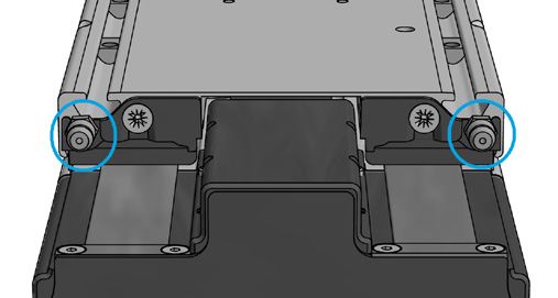
1.9        Dynamic operating load

The existing dynamic operating load must be determined and compared with the permissible dynamic operation load for linear axes
with toothed belt drive.

The dynamic operating load is calculated by the formula [2.2].

                                                          [2.2]

           Fz dyn		Existing dynamic operating load [N]
           T0		Idling speed torque [Nm]
           P		Feed constant [m]
           m		Moved mass [kg]
           a		Acceleration [ms-2]
           g		Gravity constant [9,81 ms-2]
           ∝       Assembling position [ °]

           a		Acceleration [ms-2]
           g		Gravity constant [9,81 ms-2]
           a		Assembling position [ °]
                                                          [2.3]

           Fz dyn 0		Permissible dynamic operation [N]
           Fz dyn		Existing dynamic operation [N]

1.10       Precision
The running parallelism of linear axes is mainly determined by the tolerances of the used aluminum profiles. The profiles used by us
meet or exceed the requirements of EN12020-2 for precision profiles.

The most common requirement in applications of Linear Axis is the repeatability. These values are in the data tables for all SNR Linear
Axis specified.

For more information please contact our NTN-SNR application engineers.

                                                              E 9
1.11       Gearbox selection
For the selection of the gearbox for a Linear Axis the following should be considered:

           • Maximum operating speed
           • Maximum acceleration torque
           • Nominal torque on the drive

These parameters are manufacturer information which take into account the mechanical and thermal limits of the gearbox and that
are not allowed to be exceeded

1.11.1.    Maximum operation speed

                 [2.4]                                                                [2.5]

           n		Existing operation speed [min-1]                                  n max		Maximum permissible operation speed [min-1]
           v		Velocity [ms-1]                                                   n		Existing operation speed [min-1]
           P		Feed constant [m]

1.11.2.    Maximum acceleration torque

                 [2.6]                                                                [2.7]

           Tmax		Existing acceleration speed [Nm]                               Ta max		Maximum permissible acceleration torque [Nm]
           T0		Idling speed torque [Nm]                                         Tmax		Existing acceleration torque [Nm]
           P		Feed constant [m]
           m		Moved mass [kg]
           a		Acceleration [ms-2]
           g		Gravity constant [9,81 ms-2]
           ∝		Assembling position [ °]

1.11.3.    Nominal torque on the drive

                 [2.8]                                                                                                         [2.9]

           T		Excisting torque on the drive [Nm]                                Ta 		Permissible nominal torque on the drive [Nm]
           T0		Idling speed torque [Nm]                                         T		Existing torque on the drive [Nm]
           P		Feed constant [m]
           m		Moved mass [kg]
           g		Gravity constant [9,81 ms-2]
           ∝		Assembling position [ °]

                                                                 E 10
1.12 Drive calculation
Calculations of drives are carried out exclusively by the respective drive manufacturer.
The reason for this is that NTN-SNR does not have all necessary calculation tools and basic data of these drives.
1.13 Selection of Linear Axis with toothed belt drive for 90 ° tilt mounting (wall mounting)
For Linear Axis with a toothed belt drive in a 90 ° tilted arrangement (wall mounting), the toothed belt can be displaced downwards
during operation by the gravity force to the flanged pulley. For this reason, we recommend not to exceed the stroke limit lengths
specified in Table 2.2.
Table 2.2_____ Stroke limit length for Linear Axis with toothed belt drive for wall mounting
Type Stroke limit length [mm]
AXE60Z 2 000
AXE80Z 2 500
AXE100Z 3 000
AXE110Z 2 000
AXE160Z 2 500
During operation, the centered run of the toothed belt must be checked together with the maintenance of the Linear Axis specified
in Chapter 4.7.
E 112. Mounting and start-up
2.1 Transportation and storage
SNR Linear Axis are high-precision components. Heavy shocks could damage the mechanics of the Linear Axis and impair
its function. To avoid damage during transportation and storage, the following points should be observed:
• Protection against strong vibrations or shocks, aggressive substances, moisture and contamination
• Using of a sufficiently large packaging and prevent them against slipping during transportation
• Linear Axis can have lager weights and sharp edges. The transportation must be carried out by qualified staff with
appropriate personal protective equipment (safety shoes, gloves, ...).
• Linear Axis and packaging with Linear Axis can have great length. To prevent excessive bending during transportation, the
Linear Axis and their packaging must be supported at least two points, for lengths from more than 3 m at three points.
2.2 Design of the mounting surfaces / mounting tolerances
Any deviation of the flatness, straightness and parallelism of Linear Axis or mounted axis systems leads to tensions that cause
additional loads of the guiding elements and reduce the life time. In general, the higher load and kilometerage, the higher the
requirements for the mounting and alignment of the Linear Axis or the axis system.
For a safer function of single axis or axis systems their straightness by the alignment of the individual axis must be guaranteed according
to Table 3.1:
Table 3.1 Straightness tolerance for the mounting of Linear Axis
Size Straightness tolerance after mounting / m [mm]
all 0,5
For Linear Axis is the permissible tolerance in the flatness (twisting) and the bending in the longitudinal direction is also influenced by
the torsional rigidity of the cross traverse. The resulting moment loads (My) shall not exceed the catalog values (less load moment).
It must be noted that simultaneous variations in straightness (Table 3.1), flatness, bending and parallelism (tolerance e0 and e1, Table
3.2) result in an addition of the loads on the guiding system and must be taken into account pro rata.
Additional requirements for the quality of the mounting surfaces must be considered when the tables of parallel installed Linear Axis
are rigidly connected. For a parallel installation, the Linear Axis of the AXE60, AXE80 and AXE100 are mainly suitable.
If the parallel installation of Linear Axis from other sizes is necessary, please contact for the selection process our NTN-SNR application
engineers.
E 12The mounting surfaces of the Linear Axis, as well as for the cross traverse should be machined in the assembly area in a single setup
or should be adjustable. The base tolerance e0 and the parallelism tolerance e1 of the Linear Axis from Table 3.2 (Figure 3.1) schould
be aimed for the straightness of the mountingsurfaces from the traverse cross to the moving direction.
Figure 3.1____ Tolerances of parallel Linear Axis
Table 3.2____ Mounting tolerances of parallel Linear Axis
Base tolerance e0 for traverses Base tolerance e0 Parallelism tolerance e1
Type [mm] for Standard Axis Systems1 [mm]
[mm]
AXE60 0,010 0,300 0,018
AXE80 0,010 0,300 0,020
AXE100 0,020 0,022
1-
see Chapter 7
If a machining of the mounting surfaces to above-mentioned requirement are not provided or this value is exceeded by the deflection
of the cross traverse, a control of parallelism must be made and, if necessary a correction must be made.
The diagram in Figure 3.2 shows the relationship between mounting tolerances and possible dynamic load capacity.
AXE100
120
AXE80
100
AXE60
Dynamic load capacity [%]
80
60
40
20
0,00 0,02 0,04 0,06 0,08 0,10 0,12 0,14 0,16 0,18 0,20 0,22 0,24 0,26 0,28 0,30
Mounting tolerances [mm]
Figure 3.2____ Dynamic load capacity of Linear Axis related to the mounting tolerances
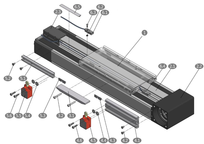
E 132.3 Mounting instruction
When mounting the linear axis (incomplete machine) listed below conditions must be fulfilled so that they can be assembled correctly
and without affecting the health and safety of staff with other parts to form a complete machine.
Caution! The motor housing can reach high temperatures during operation..
The Linear Axis should be installed so that the structure-borne
noise is minimized. Other machine parts should be designed so
that they do not lie in the resonance range of the Linear Axis.
SNR Linear Axis of the AXE series can be fastened by sliding
blocks or fastening strips at plane surfaces or other Linear Axis
from the AXE range. The number of mounting points must be
matched to the application.
The fastening strips are laterally hooked on the Linear Axis profile
and, thanks to its special design are easy to assemble by screwing
them from above (Figure 3.3).
Figure 3.3 ___ Fastening strips AXE
Alternatively Linear Axis can also be mounted on swivel-sliding
blocks, which can also be freely positioned along the entire length
(Figure 3.4).
Figure 3.4____ Sliding blocks AXE
Generally, the number of mounting points must be matched to the application in all types of fastening. With punctual support of the
Linear Axis, the resulting bending does not impair the function nor impair the required accuracy.
E 142.4 Mounting of parallel Linear Axis
Generally, we recommend the alignment of parallel Linear Axis with an assembled crossbar. This is the only safe method to reduce
tensioning and thus interference of the life time to a minimum. The mounting has to be carried out according to the following steps:
1. Align the first Linear Axis (drive axis) straight and assemble it completely.
2. Align the second Linear Axis parallel and the ends in line and tighten only slightly, for the examination under point 6.
3. Move the tables in one end position.
4. Place the traverse (or crossbar).
5. If a relevant deflection is to be expected, apply the load or simulate it.
6. Check the base tolerance e0 (Chapter 3.2) with the feeler gauge. If necessary insert foil sheets or correct angular position
of the Linear Axis.
7. Align traverse (or crossbar) and fix it.
8. Loosen the mounting screws of the parallel Linear Axis, so that a slight displacement is possible.
9. Move the table to the respective mounting position and tighten the screws. Start with the end position.
10. Finally, loosen the connection to the tables completely and tighten it again.
2.5 Tightening torques
For all assemblies described below, the tightening torques of the screws is summarized in Table 3.3 and 3.4.
Table 3.3____ Tightening torque of the couplings
Tightening torque
Type
Clamping hub coupling [Nm] Gearbox [Nm] Gearbox flange [Nm]
AXE40A 1,34 2,06 0,98
AXE60A
10,00 6,86 4,41
AXE60Z
AXE80Z 10,00 6,86 4,41
AXE100Z 25,00 33,3 14,70
AXE110Z 10,00 6,86 4,41
AXE160Z 10,00 6,86 4,41
Table 3.4_____ Tightening torques for drive assembly
Shaft diameter Clamping screw
Type
[mm] Wrench size [Nm] Tightening torque [Nm]
AXE40A all 3 2,0
AXE60A ≤ 14 3 4,5
AXE60Z 19 4 9,5
AXE80Z all 4 9,5
AXE100Z all 5 16,5
≤ 14 3 4,5
AXE110Z
19 4 9,5
AXE160Z all 4 9,5
E 152.6 Form-fitted mounting of planetary gearboxes
The form-fitted mounting of planetary gearboxes on Linear Axis with toothed belt drive have to proceed according to the following
steps (Figure 3.5). The tightening torques from Table 3.3, Chapter 3.5 must be taken into account.
1. Place the adapter flange 2 on the
planetary gearbox 1 and tighten fastening
screws 3 . If this is not smoothly possible,
pull the gearbox shaft into the hollow shaft
with a screw and washer.
2. Insert the gearbox shaft with the feather
key into the hollow shaft 6 of the Linear
Axis. If this is not smoothly possible, pull
the gearbox shaft into the hollow shaft
with a threaded rod and washer. Place
the washer 5 if available) on the adapter
flange and screw them to the drive head
by using the screws 4 .
Figure 3.5____ Form-fitted mounting of planetary gearboxes on Linear Axis with toothed belt drive
2.7 Force-fitted mounting of couplings
The force-fitted mounting of couplings on Linear Axis with toothed belt drive have to proceed according to the following steps (Figure
3.6). The tightening torques from Table 3.3, Chapter 3.5 must be taken into account.
1. Insert the coupling hub 1 with feather key
2 in the hollow shaft of the Linear Axis.
2. Screw the coupling hub to the hollow
shaft by using of the fastening screws 3 .
3. Insert elastomeric gear rim 4 .
Figure 3.6____ Force-fitted mounting of couplings on Linear Axis with toothed belt drive
E 162.8 Mounting of planetary gearboxes via coupling and coupling cone
The mounting of planetary gearboxes via coupling and coupling cone on Linear Axis with toothed belt drive have to proceed according
to the following steps (Figure 3.7). The tightening torques from Table 3.3, Chapter 3.5 must be taken into account.
1. Insert the gearbox shaft 2 into the coupling hub 1 and tighten the coupling hubs with the tensioning screw 3 .
2. Place the planetary gearbox 1 on the coupling cone 4 and screw it by using of the fastening screws 5 .
3. Insert this assembling group with the drive head screwed coupling hub with elastomeric gear rim 6 , and tighten them with
the screws 7 . Take in account the dimensions LK and L2 (Figure 3.8) from Table 6.20, Chapter 6.2.3.2.
Figure 3.7____ Mounting of planetary gearboxes via coupling and coupling cone
Figure 3.8____ Mounting dimension
E 172.9 Mounting of the gearbox flange
For the different dimension of the motor flanges, different gearbox flanges for the planetary gearboxes are available. The mounting of
the gearbox flanges have to proceed according to the following steps (Figure 3.9), regardless of whether the gearbox is form-fitted
connected to the Linear Axis or mounted via the coupling and coupling cone. The tightening torques from Table 3.3, Chapter 3.5
must be taken into account.
1. Place the gearbox flange 2 on the planetary gearbox 1 .
2. Screw the gearbox flange by using the fastening screws 3 .
Figure 3.9____ Mounting of the gearbox flange
E 182.10 Drive assembly
The assembling of drives on Linear Axis with toothed belt drive and planetary gearbox is carried out according to the following steps
(Figure 3.10). The tightening torques from Table 3.4, Chapter 3.5 must be taken into account.
1. Place the Linear Axis 1 laterally so that
the mounting flange of the drive 2 faces
upwards.
2. Lubricate the drive shaft, bore of the hollow
shaft and bolt spacer.
3. Move the slider 3 until the clamping screw
is visible in the access hole 4 .
4. If a bolt spacer is necessary for the motor
shaft diameter, insert it into the gearbox bore.
It is important to ensure that the slot of the
bolt spacer is offset by 90 ° to the clamping
screw.
5. Insert drive 5 .
6. Insert and tighten the fastening screws 6 .
7. Tighten the clamping screw with the required
tightening torque.
8. Close the access hole in the mounting flange
of the drive 2 with the supplied plug.
Figure 3.10___ Drive assembly for Linear Axis with planetary gearbox
2.11 Mounting of connecting shafts for parallel Linear Axis
The mounting of connecting shafts for parallel Linear Axis with toothed belt drive have to proceed according to the following steps
(Figure 3.11). The tightening torques from Table 3.3, Chapter 3.5 must be taken into account.
1. Mounting of the Linear Axis according to the
information in Chapter 3.2 and 3.4.
2. Mount the coupling hubs 1 according to
the description in Chapter 3.7.
3. For parallel Linear Axis with connecting shaft,
couplings with half-shell clamping hub 2 / 5
are used.
4. Move the slider units 4 from both Linear
Axis into one end position.
5. Insert one half of each half-shell clamping
hubs 2 into the elastomer gear rims.
6. Fit the connecting shaft 3 , insert the second
half of the half-shell clamping hubs 5 and
tighten them. The half-shell couplings allow
a subsequent mounting and dismounting of
the connecting shaft without the dismounting
of the Linear Axis.
Figure 3.10___ Mounting of parallel Linear Axis with connecting shaft
E 192.12 Mounting of limit switches
Depending on the version, Linear Axis of the AXE series can be equipped with mechanical limit switches or with inductive proximity
switches.
The respective limit switches and the actuating element (Chapter 6.3.5) are provided with the specified ID number as a complete
mounting kit including all screws and fastening elements.
In the following chapters we describe the mounting of the limit switches for the various drive variants.
2.12.1. Mounting of limit switches for Linear Axis AXE_Z (except AXE110Z)
For the mounting of the limit switches and actuating elements the following steps have to be proceeded according in accordance to
Figure 3.12. The table 1 and the profile 1 of the Linear Axis are designed symmetrically so that mounting on both
Figure 3.12___ Mounting of limit switches for Linear Axis AXE_Z
Actuating element
Place the washers 3.2 on the screws 3.3 and screw the actuating element 3.1 of the limit switches with the table 1 . It is important
to ensure that the bevels of the actuating element are facing down.
Mechanical limit switches
Swing the sliding blocks 4.1 into the upper lateral groove of the profile 2 . Move the limit switches 4.2 with the sliding blocks and
the screws 4.3 to the desired switching position and fasten it.
Inductive proximity switches (except AXE160Z)
Screw the bracket of the limit switch 5.3 with the screws 5.4 slightly with the sliding blocks 5.1 . Insert the sliding blocks 5.1
into the upper lateral groove of the profile 2 and tighten the screws 5.4 until the sliding blocks 5.1 turn into the groove. Insert the
inductive proximity switch 5.2 from below into the bracket 5.3 and adjust it to a maximum distance of 1.2 mm from the actuating
element 3.3 and tighten the screws 5.4 .
The inductive proximity switches of the Linear Axis AXE160Z are mounted on the profile top.
The mounting is the same as for the Linear Axis AX110Z and is described in Chapter 3.12.3.
E 202.12.2. Mounting of inductive proximity switches (groove installation) for Linear Axis AXE60Z, AXE80Z and AXE100Z
Alternative, to the limit switches described in Chapter 3.12.1, the Linear Axis AXE60, AXE80 and AXE100 can also be equipped with
inductive proximity switches for groove installation. The mounting of the limit switches and the actuating element must be carried out in
the following steps according to Figure 3.13. For this switch version, table 1 and the profile 2 of the Linear Axis are also symmetrically
designed, so that mounting on both sides is possible.
Figure 3.13___ Mounting of inductive proximity switches for groove installation
Actuating element
Insert the screws 3.3 through the holes of the actuating element 3.2 , place the washers 3.1 on the screws and screw the unit to
the lateral threaded holes of the table 1 .
Inductive proximity switches for groove installation
Insert or swing in the limit switches 4.1 from the deflection side into the upper groove of the profile 2
After positioning, screw the limit switches tight with the set screws 4.2 . It must be ensured that the cable guiding of the limit switch
on the drive side takes place as described in Chapter 6.3.2. An adjustment of the switching distance is not necessary. For AXE80 and
100, the groove should be closed by agroove insert for safe cable routing. The groove insert is not part of the switch set and must be
ordered separately (ID number 101841, chapter 6.5).
E 212.12.3. Mounting of limit switches for Linear Axis AXE110Z and proximity switches for AXE160Z
For the mounting of the limit switches and actuating elements the following steps have to be proceeded in accordance to Figure 3.14.
The table 1 , the drive head 2.2 and the deflection head 2.3 of the Linear Axis are symmetrically designed, so that mounting on
both sides is possible.
Figure 3.14___ Mounting of limit switches for Linear Axis AXE110Z
Actuating element to ensure that the cable guiding as shown in Chapter 6.3.2, is carried
out. An adjustment of the switching distance is not necessary.
Insert the screws 3.2 through the holes of the actuating element The upper profile groove should be closed by a groove insert 6.5 .
3.1 and screw the unit to the lateral threaded holes of the table 1 .
The groove insert (ID number 173218, Chapter 6.5) does not
belong to the limit switch set and must be ordered separately.
Mechanical limit switches on the drive head
Fix the profile segment 4.1 to drive head 2.2 with screws 4.2
Insert the sliding blocks (Form E) 4.3 into the upper groove of
profile segment 4.1 . Insert the screws 4.6 through the holes of
Cable guiding
the limit switch 4.5 , place the washers 4.4 and screw the unit
with the sliding blocks 4.3 .
Mechanical limit switches on the deflection head
Fix the profile segment 5.1 to deflection head 2.3 with screws
5.2 . Insert the sliding blocks (Form E) 5.3 into the groove of
profile segment 5.1 . Insert the screws 5.6 through the holes of
the limit switch 5.5 , place the washers 5.4 and screw the unit
with the sliding blocks 5.3 .
Inductive proximity switches
Insert the hexagon nuts 6.2 through the recess on the deflection
side into the upper groove of profile 2.1 and position them. Pass
the cable of the drive-side switch 6.4 under the table 1 . Fix the
proximity switches 6.1 and 6.4 with the screws 6.3 . It is important
Figure 3.15___ Cable guiding for inductive proximity switches AXE110Z
E 222.12.4. Mounting of limit switches on the drive head of Linear Axis AXE_A with moving profile
For the mounting of the limit switches and actuating elements the following steps have to be proceeded in accordance to Figure
3.16. The drive head 1 and the profile 2 of the Linear Axis are designed symmetrically so that mounting on both sides is possible.
Figure 3.16___ Mounting of limit switches on the drive head of Linear Axis AXE_A with moved profile
Actuating element for mechanical limit switches
Insert the sliding blocks 3.3 nto the upper groove of the profile 2 . Insert the screws 3.1 through the holes of the actuating element
3.2 and screw it to the sliding blocks 3.3 . It is important to ensure that the bevels of the actuating element are facing up.
Mechanical limit switches
Insert the screws 4.2 through the mounting holes of the limit switches 4.1 and screw them to the drive head 1 .
Actuating element for inductive proximity switches
Insert the sliding blocks 5.1 into the upper groove of the profile 2 . Insert the screws 5.3 through the holes of the actuating element
5.2 and screw it to the sliding blocks 5.1 . It is important to ensure that the bevels of the actuating element are facing down.
Inductive proximity switches
Screw the bracket of the limit switch 6.2 with the screws 6.3 slightly with the drive head 1 . Insert the inductive proximity switch
6.1 from above into the bracket 6.2 and adjust it to a maximum distance of 1.2 mm from the actuating element 5.2 and tighten
the screws 6.3 .
E 232.12.5. Mounting of limit switches on the profile of Linear Axis AXE_A with moving drive head
For the mounting of the limit switches and actuating elements the following steps have to be proceeded in accordance to Figure
3.17. The drive head 1 and the profile 2 of the Linear Axis are designed symmetrically so that mounting on both sides is possible.
Figure 3.17___ Mounting of limit switches on the profile of Linear Axis AXE_A with moved drive head
Actuating element for mechanical limit switches
Insert the screws 3.2 through the holes of the actuating element 3.1 and screw it to the drive head 1 . It is important to ensure that
the bevels of the actuating element are facing down.
Mechanical limit switches
Insert the sliding blocks 4.1 into the upper groove of the profile 2 . Insert the screws 4.3 through the mounting holes of the limit
switches 4.2 and screw them to the sliding blocks 4.1 .
Actuating element for inductive proximity switches
Insert the screws 5.3 through the holes of the actuating element 5.1 , place the washers 5.2 and screw the unit with the drive head 1 .
Inductive proximity switches for groove installation
Insert the limit switch 6.1 from the deflection side into the upper groove of the profile 2 . Tighten the switches after positioning with
the set screws 6.2 . It is important to ensure that the cable guiding as shown in Chapter 6.3.2, is carried out. An adjustment of the
switching distance is not necessary.
E 242.13 Start-up of Linear Axis
Linear Axis can travel at high velocity with a large degree of force. Slider fittings can lead to bodily injury or material damage upon
collision. Start-up should thus be performed with the utmost caution.
Furthermore, it should be ensured upon start-up that the permissible loads are not exceeded and the slider fittings are securely
fastened. It should also be ensured that the maximum possible travel distance is not exceeded. If travel distance is limited with limit
switches, they should be previously tested in terms of performance and correct positioning.
Hazards can arise through unintentional descending of vertical Linear Axis. The end user must take the necessary precautions.
according EN ISO 13849-1
The manufacturer is not liable for damages resulting from non-observance of these start-up instructions. The user
bears sole responsibility for all risks.
E 253. Maintenance and lubrication
3.1 General information
Caution!
All maintenance and service works must be carried out in power off and secured stage.
The motor housing can reach high temperatures during operation.
3.2 Lubrication
For the reliable operation of the Linear Axis, a sufficient lubrication is essential.
The lubrication should ensure a lubricant film (oil film) between rolling elements and raceways of the guiding and drive elements to
prevent wear and premature fatigue of the components.
In addition, the metallic surfaces are protected against corrosion. Furthermore, the lubricant film allows a smooth sliding of the seals
on the surfaces and reduces also the wear of them.
Insufficient lubrication not only increases the wear, it reduces also significantly the life time.
An optimal selection of the lubricant has a decisive influence on the function and life time of the Linear Axis. In order for the function of
the system to be not affected and remain over a long period lubricated according to the environmental conditions; specific requirements
should be defined.
Such environmental conditions and factors may be for example:
• Condensation and splash water effects
• High vibration stress
• High acceleration and velocity
• Continually short stroke movement (< Table length)
• Dirt and dust
3.3 Lubricants
When lubricating the guide system of the Linear Axis, the lubricant has the following function:
• Reduction of the friction
• Reduction of the starting moment
• Protection against wear
• Corrosion protection
• Noise reduction
Linear Guides
Lithium soap greases with the marking KP2-K according to DIN 51825 and NLGI class 2 according to DIN 51818 with EP additives
are to be used under normal conditions. SNR LUB HEAVY DUTY is used as standard grease in the Linear Axis of the AXE series.
Table 4.1 contains the data for the lubricant SNR LUB HEAVY DUTY used for NTN-SNR linear guides.
The use of greases containing solid additives (for example, graphite or MoS2) is not allowed.
Table 4.1_____ SNR LUB HEAVY DUTY
Description Base oil / NLGI class Worked penetration Basic oil Density Propertie Application area
Type ofsoap DIN51818 DIN ISO 2137 at 25°C viscosity [mg/cm3]
[0,1mm] DIN 51562 at
40°C [mm2/s]
SNR LUB Mineral oil / 2 295 ca. 115 890 Very high protection against wear • General engeneering
HEAVY DUTY Lithium with EP and corrosion • High loads
additives
E 263.4 Lubrication methods
SNR Linear Axis can be supplied with lubricant by manual grease guns or by central lubrication systems.
3.4.1. Manual grease gun
When using manual grease guns (Figure 4.1), the guiding and drive elements of the Linear Axis are lubricated by the mounted
grease nipple.
Figure 4.1____ SNR Manual grease gun
3.4.2. Automatic electro-mechanical lubricator
DRIVE BOOSTER
The grease nipples of SNR Linear Axis of the AXE series can be
replaced by connections for a central lubrication system (Chapter
6.6).
A suitable central lubrication system is the CONTROL BOOSTER
(Figure 4.2). The CONTROL BOOSTER has six connectors for
lubricant lines, which can be configured individually and can be
optionally be equipped with 250 cc and 500 cc volume of lubricant
in the CONTROL REFILL unit. The CONTROL REFILL unit can be
after emptying replaced or be factory-provided refilled.
Figure 4.2____ CONTROL BOOSTER
For more information please contact our NTN-SNR application engineers.
E 273.5 Lubrication points
Depending on the size and drive type, SNR Linear Axis have a different number of lubrication points in different positions.
AXE60Z, AXE80Z, AXE100Z
The Linear Axis AXE60Z, AXE80Z and AXE100Z are equipped with
a grease nipple at both front sides of the slider unit (Figure 4.3) to
ensure the best possible accessibility. This means that each per
lubrication interval and its amounts of the lubricant indicated in
Chapter 4.6 may be introduced only on one side of the Linear Axis
in the appropriate grease nipple. As grease nipples the hydraulic
type grease nipples are mounted.
Figure 4.3____ Lubrication points for AXE60Z, AXE80Z, AXE100Z
AXE110Z, AXE160Z
The Linear Axis AXE110Z have two grease nipples at the deflection
side and the Linear Axis AXE160Z two grease nipples each at
both front sides of the slider unit (Figure 4.4) to ensure the best
possible accessibility. This means that each per lubrication interval
and its amounts of the lubricant indicated in Chapter 4.6 may
be introduced only on one side of the Linear Axis in both grease
nipples. As grease nipples the hydraulic type grease nipples are
mounted.
Figure 4.4____ Lubrication points for AXE110Z, AXE160Z
AXE40A, AXE60A
The Linear Axis AXE40A und AXE60A are equipped with a grease
nipple at sides of the drive head (Figure 4.5) to ensure the best
possible accessibility. This means that each per lubrication interval
and its amounts of the lubricant indicated in Chapter 4.6 may
be introduced only on one side of the Linear Axis in both grease
nipples. As grease nipples the cup head grease nipples are
mounted.
Figure 4.5____ Lubrication points for AXE40A, AXE60A
3.6 Amounts of lubricant Table 4.2_____ Lubrication amount of the linear guides
The following table contains the information to the corresponding Type Lubrication amount per lubrication point [cm³]
amounts of lubricant for re-lubrication with the standard lubricant B C D
for the guiding elements. AXE_Z
AXE60Z 1,0
The amounts of the lubricant for the re-lubrication of Linear Axis AXE80Z 2,8
with Linear guides are summarized in Table 4.2. 2,4
AXE100Z
AXE110Z 0,6
AXE160Z 2,8
AXE_A
AXE40A 0,3
AXE60A 1,0
E 283.7 Lubrication intervals
Delivery condition
SNR Linear Axis have already an initial lubrication on delivery. After assembly, the Linear Axis should be according the previous
chapters.. For an optimal grease distribution in the system, this process should take place in two to three steps with intermediate
movement over a longer stroke.
When restarting a system after a prolonged shutdown, a re-lubrication with the double amount of lubricant which is specified in
Chapter 4.5 is recommended.
When the lubricant is changed at any time during the operation of the system, the miscibility of the lubricants must be absolutely tested.
Influence factors
The lubrication intervals are influenced by many factors (Chapter 4.1). The biggest influence usually has the load and the existing
contamination. The exact lubrication intervals can only be determined after testing under real operating conditions and assessment
over a sufficiently long period for a concrete application.
In Table 4.3 are summarized the usability of the different Linear Axis for the different degrees of pollution.
Table 4.3_____ Degrees of pollution for Linear Axis
Degree of pollution Application area Usable Linear Axis AXE
Without pollution - Laboratories all
- very clean working areas
Low level of pollution - Assembling areas with very low occurrence all
of dust and dirt
Medium level of pollution - Production areas and machineswith higher occurrence only AXE110 and AXE160
of dirt
The lubrication intervals of the Linear Guides are shown in the diagram in Figure 4.6, depending on the contamination.
As the lubricant manufacturers give no general guarantee for the service life time of their products, we recommend at low kilometerage
a re-greasing interval of at least once a year.
250
medium level of pollution
200
low level of pollution
% of the dynamic load capacity
150 without pollution
100
50
0
0 500 1 000 1 500 2 000 2 500 3 000 3 500 4 000 4 500 4 000 5 000 5 500 6 000 6 500 7 000 7 500 8 000 8 500 9 000 9 500 10 000
Travel distance [km]
Figure 4.6____ Re-lubrication intervals of Linear Guides
If necessary, longer lubrication intervals are possible, after consultation with the lubricant manufacturer for a defined application.
For re-lubrication, mineral oil-based lithium soap greases KP2-K according to DIN 51825 and NLGI class 2 are to be used; otherwise
the compatibility must be checked.
Greases containing solid additives (for example, graphite or MoS2) shall not be used.
E 293.8 Cover strip replacement
3.9.1. Cover strip replacement for the Linear Axis AXE110 and AXE160
For the replacement of the cover strip for Linear Axis AXE110Z and AXE160Z, the following steps in accordance to Figure 4.7 must
be observed:
1. Disassemble fastening screws 2 and end plate 1 .
2. Disassemble grease nipple 3 . Remove the washer 4
and the cover strip deflection 5 .
3. Disassemble the fastening screws 6 end remove the
clamping plate 7 .
4. Pull the cover strip 8 out and replace it by a new one.
5. To fasten, tighten the cover slightly and follow the steps
2 and 3 in reverse order. Here the cover strip should not
rub against the table. This can be checked by inspection
holes in the base of the table grooves (closed with plastic
caps). Cut the cover strip 8 behind the clamping plate
7.
6. Close the Linear Axis with the end plate 1 .
Figure 4.7____ Cover strip replacement
3.9 Wear part sets
For Linear Axis of the AXE series are wear parts sets available. Table 4.6 summarizes the wear parts sets and the cover strips including
the ID numbers.
The length of the cover strip is specified in millimeters. To mount the cover strip ensure the ordered length per side should be about
200 to 300 mm longer than the Linear Axis. The order length of cover strip is rounded up to the next meter. Per Linear Axis are two
cover strips necessary.
The cover strips for Linear Axis of the AXE series can be used universally.
Table 4.6_____ Wear part sets and cover strips
Type code Designation ID Number
AX-SP-110-A-WPS Wear part set for AXE110Z 268344
AX-SP-160-A-WPS Wear part set for AXE160Z 268345
AX-SP-CST-U-19,0-1M Cover strip, 1 m 459772
AX-SP-CST-U-19,0-2M Cover strip, 2 m 461092
AX-SP-CST-U-19,0-3M Cover strip, 3 m 461093
AX-SP-CST-U-19,0-4M Cover strip, 4 m 461094
AX-SP-CST-U-19,0-5M Cover strip, 5 m 461096
AX-SP-CST-U-19,0-6M Cover strip, 6 m 461097
AX-SP-CST-U-19,0-7M Cover strip, 7 m 461098
E 30Notes
31Notes
321. Systemtechnologie
1.1 Definitionen
Linearachsen stellen einbaufertige Einheiten aus einer Kombination von präzisen Führungs- und Antriebselementen dar. Dadurch
sind Linearachsen mit ihren Variationsmöglichkeiten kostengünstige und von den Abmessungen äußerst kompakte Bauelemente für
Maschinen, mit denen Anlagen in kürzester Zeit montiert und in Betrieb genommen werden können.
Für die Auswahl der Linearachsen können nachfolgende Kriterien Grundlage sein:
WIEDERHOL- Bei der Wiederholgenauigkeit wird ein beliebiger Punkt mehrfach aus einer Richtung vom gleichen
GENAUIGKEIT Ausgangspunkt angefahren und die Abweichung zum Sollwert gemessen. Der Vorgang wird für
verschiedene Punkte wiederholt. ± 50% der Differenz zwischen maximaler und minimaler Abweichung
wird als Wiederholgenauigkeit angegeben.
POSITIONIER- Bei Messung der Positioniergenauigkeit werden mehrere Punkte in einer Richtung angefahren und die
GENAUIGKEIT Differenz zwischen Sollweg und tatsächlich zurückgelegtem Weg gemessen. Die Positioniergenauigkeit
ist die absolute Maximaldifferenz.
LAUFPARALLELITÄT Eine mittig auf der Schlitteneinheit montierte Messuhr wird über den gesamten Hub verfahren. Die
Laufparallelität ist die maximale Differenz der Ablesewerte.
Für die Auswahl der SNR - Linearachsen stehen ebenfalls unsere Vertriebs- und Anwendungsingenieure mit langjährigen Erfahrungen
zur Verfügung.
1.2 Einbauerklärung für eine unvollständige Maschine (Machinery directive 2006/42/EG)
Hiermit erklärt der Hersteller SNR WAELZLAGER GMBH, Friedrich-Hagemann-Straße 66, D-33719 Bielefeld, Germany der
unvollständigen Maschinen der Produktfamilien „Linearachse AXE“:
• Folgende grundlegende Sicherheits- und Gesundheitsschutzanforderungen nach Anhang I der Direktive 2006/42/EG
sind angewandt und eingehalten:
Allgemeine Grundsätze:
1.1. Allgemeines
1.3. Schutzmaßnahmen gegen mechanische Gefährdungen
1.5. Risiken durch sonstige Gefährdungen
1.6. Instandhaltung
1.7. Informationen
• Die speziellen technischen Unterlagen nach Anhang VII B wurden erstellt.
• Wir werden der zuständigen Behörde ggf. die vorgenannten speziellen technischen Unterlagen in Form von speziellen
technischen Unterlagen gemäß Anhang VII Teil B übermitteln.
• Die vorgenannten speziellen technischen Unterlagen können bei der Qualitätssicherungsabteilung, SNR Wälzlager GmbH,
Friedrich-Hagemann-Straße 66, D-33719 Bielefeld angefordert werden.
• Die Konformität mit den Bestimmungen der EN ISO 12100: 2010 "Sicherheit von Maschinen – Allgemeine Gestaltungsleitsätze
- Risikobeurteilung und Risikominderung"
• Die Inbetriebnahme ist so lange untersagt, bis festgestellt wurde, dass - soweit zutreffend - die Linearachse oder das
Linearachssystem, die in eine unvollständige Maschine eingebaut werden soll, den Bestimmungen der der Maschinenrichtlinie
2006/42/EG entspricht.
i.V. Ulrich Gimpel
(Industry Engineering Division Head)
SNR WÄLZLAGER GMBH - Friedrich-Hagemann-Straße 66 D-33719 Bielefeld, Germany
Bielefeld, Dezember 2019
D 5You can also read