APEC-CAST MOTOR REPAIRS PROJECT - CLASP
←
→
Page content transcription
If your browser does not render page correctly, please read the page content below
APEC-CAST MOTOR REPAIRS PROJECT
ON BEHALF OF THE APEC EXPERT GROUP ON ENERGY EFFICIENCY AND CONSERVATION

With support from the International Copper Association, the China National Institute of
Standardization, CLASP and the Super-efficient Equipment and Appliance Deployment Initiative

Task 1: Existing and Best Practices
in Motor Repair

Final Report

November 2013

APEC-CAST Motor Repairs Project
                               Final report - Task 1: Existing and Best Practices in Motor Repair

                               ACRONYMS
AC       Alternating current
AEMT     Association of Electrical and Mechanical Trades
APEC     Asia-Pacific Economic Cooperation
CLASP    Collaborative Labeling and Appliance Standards Program
DC       Direct current
EASA     Electrical Apparatus Service Association
EGEE&E   Expert Group of Energy Efficiency and Conservation
GMI      Green Motor Initiative
ICA      International Copper Association
IEA      International Energy Agency
ODP      Open Drip Proof
TEFC     Totally Enclosed Fan-cooled
US       United States of America

                                                                                               ii
APEC-CAST Motor Repairs Project
                                                              Final report - Task 1: Existing and Best Practices in Motor Repair

                                               TABLE OF CONTENTS
EXECUTIVE SUMMARY ................................................................................................................... VI
INTRODUCTION ............................................................................................................................... 11
1                   ENERGY LOSSES IN AC INDUCTION MOTORS ...................................................... 13
    1.1      Stator Copper Loss .......................................................................................................... 13
    1.2      Rotor Copper Loss ........................................................................................................... 13
    1.3      Iron Loss ........................................................................................................................... 14
    1.4      Friction and Windage Loss .............................................................................................. 14
    1.5      Stray Load Loss................................................................................................................ 14
2                   CLASSIFICATION OF MOTOR FAILURES CAUSES ................................................ 15
3                   REVIEW OF PRACTICES IN MOTOR REWINDING AND REPAIR ........................... 16
    3.1      Poor Practices during AC Electrical Motors Repairs ..................................................... 17
    3.2      Best Practices in Motor Rewind/Repair .......................................................................... 17
        3.2.1      Rewind/Repair .............................................................................................................. 17
        3.2.2      Rotor Replacement ....................................................................................................... 18
        3.2.3      Motor Replacement Criteria .......................................................................................... 18
    3.3      Summary of rewind/repair practices in surveyed countries .......................................... 19
        3.3.1      Rewind/Repair Techniques in Five Surveyed Countries................................................ 19
        3.3.2      Availability of Tools and Equipment in Repair Shops .................................................... 22
4                   PRESENTATION OF THE TECHNICAL AND ECONOMIC ANALYSIS MODEL ....... 25
    4.1      Model Description ............................................................................................................ 25
        4.1.1      Technical Model – Algorithm to Evaluate the Efficiency Losses Associated with Each
                        Repair Practice .................................................................................................... 25
        4.1.2      Repair Cost and Economic Analysis Model................................................................... 30
        4.1.3      Market Potential Model ................................................................................................. 31
    4.2      Application of the Technical Algorithm to Determine the Decrease in Energy
               Efficiency ...................................................................................................................... 32

                                                                                                                                                  iii
APEC-CAST Motor Repairs Project
                                                             Final report - Task 1: Existing and Best Practices in Motor Repair

CONCLUSION ................................................................................................................................... 34
REFERENCES .................................................................................................................................. 36
APPENDIX I METHODOLOGY AND SCOPE OF THE STUDY......................................................... 37
APPENDIX II SUMMARY OF EXISTING POOR PRACTICES AND THEIR IMPACTS ON MOTOR
            LOSSES ..................................................................................................................... 41
APPENDIX III EASA AND GREEN MOTORS PRACTICES GROUP (GMPG) RECOMMENDED
             BEST PRACTICES FOR THE REWIND/REPAIR OF ELECTRIC MOTORS .............. 43
APPENDIX IV SURVEY FORM FOR REPAIR SHOPS ..................................................................... 49
APPENDIX V RESULTS OF SECTION II OF THE SURVEY ............................................................. 43
APPENDIX VI RESULTS OF ICA SIMULATION ............................................................................... 45

                                                                                                                                              iv
APEC-CAST Motor Repairs Project
Final report - Task 1: Existing and Best Practices in Motor Repair
LIST OF TABLES
Table 1: Shops by Size Surveyed in Each Country ............................................................................ 19
Table 2: Tools Considered in the Survey ........................................................................................... 22
Table 3: Equipment Considered in the Survey ................................................................................... 24
Table 4: Source of Losses and Activities Associated with Part of the Repair Process ........................ 26
Table 5: Relationship between the Survey Information and the Repair Activities ............................... 28
Table 6: Comparison of ICA and the Study Model.............................................................................. 29
Table 7: Motor Characteristics ........................................................................................................... 30
Table 8: Partial Application of the Technical Model on a 50 kW Motor with up to 4 Poles .................. 33
Table 9: AC Induction Motor Range Covered by the Study ................................................................ 40
LIST OF FIGURES
Figure 1: Energy Efficiency Modeling of Motor Repair Techniques .......................................................x
Figure 2: Components of an AC Induction Motor ............................................................................... 15
Figure 3: Electric Motor Categories .................................................................................................... 38
vAPEC-CAST Motor Repairs Project
Final report - Task 1: Existing and Best Practices in Motor Repair
EXECUTIVE SUMMARY
Background of the Study
Electric motors in motor-driven systems represent a major energy end usage, and account for
between 43% and 46% of all global electricity consumption1. In industry applications at the global
level, it is estimated that motors consume approximately 64%2 of the energy consumed by all electric
motor-driven systems across sectors (industrial, commercial, residential and transport as well as
agriculture).
A large number of motors in various sectors fail during operation each year; as a result, the majority of
failed motors are repaired and put back into service. In most developing countries, these failed motors
are typically repaired by using poor3 practices, which degrade the initial motor efficiency when there
are still new. By contrast, in developed economies, such as the United States (US) and western
European countries, advanced repair and re-winding practices allow maintaining or slightly increasing
the efficiency of motors. Quite often, these advanced techniques do cost the same as those less
refined techniques to perform. If improved motor repair practices are adopted, they could generate
enormous energy savings in developing countries.
The primary aim of this study is to estimate the energy efficiency improvement potential related to
available technical solutions by adopting best motor repair practices, which can later be included in
related standards. The study can benefit policy-makers and standard-setting bodies because it can
help raise their awareness regarding the potential for energy savings related to repair and preventive
maintenance of installed motors. The study team is comprised of Econoler experts and an industry
specialist from the Research and Development (R&D) laboratory of ABB, one of the international
market leaders in the field of motor and electrical machinery repair techniques.
This report documents and analyzes current best practices in motor rewinding and repair as well as
evaluates the gap between these best practices and practices being used in five representative APEC
economies: China, Japan, New Zealand, the US, and Vietnam.
The data collection methodology to support the gap analysis was based on a literature review of
research conducted in the field of motor repair practices, field research through in-person interviews
conducted by experts at motor repair facilities, phone interviews and email surveys with other key
stakeholders, such as government agencies, motor experts, etc. The key findings are presented in the
following sections.
1
International Energy Agency (IEA), 2011, “Energy-Efficiency Policy Opportunities for Electric Motor-Driven Systems”,
Energy efficiency Series, p.11
2
Ibid.
3
Based on interviews with motor experts (March 2013)
viAPEC-CAST Motor Repairs Project
Final report - Task 1: Existing and Best Practices in Motor Repair
Motor Failure Causes
Three main types of factor, namely mechanical, electrical and improper selection can cause electric
motors to fail. Mechanical factors are associated with bearing failures and other mechanical factors.
Results of several studies suggest that the primary cause of motor mechanical failures is a bearing
problem, which can be caused by a combination of contamination, lubrication, improper assembly,
misalignment of the rotor shaft, or overloading.
As for electrical factors, they are mainly associated with winding failures, mostly due to excessive
temperature increases caused by overloading leading. Winding failures are stator insulation failures,
which include ground insulation failures and inter-turn insulation failures. Other factors which can also
contribute to winding failures are supply voltage variations and particularly low voltage, improper or
poor electrical connections, vibration and insulation contamination. Sometimes, electrical failures also
occur in motors because of misapplication, which is the failure to correctly match a motor’s
characteristics with the load requirements of the driven equipment (e.g., starting current, improper and
substandard motor starter, starting torque requirements, etc.).
Considering the prevalence of failure modes in electric motors and the potential effects of each failure
repair method on the efficiency of the repaired unit, this study primarily has focused on electrical
failures, especially stator winding failures and rotor failures. It should be mentioned that the stator is
composed of laminations of high-grade sheet steel. The rotor consists of laminations of slotted
ferromagnetic material; the rotor can be either the squirrel-cage type or the wound-rotor type. Bearing
failure is not given the same amount of attention as that given to electrical failure because the former
is not so serious in terms of impact on motor efficiency. Bearing losses are taken into account in
friction and windage losses, which can increase after motor repair and rewind using bad practices.
As a result, the study covered repair practices associated with stator and rotor failures. These
practices include: (i) rewind practices, such as winding removal, winding configuration and
modification, impregnation, etc.; (ii) lamination repair or replacement; and (iii) rotor repair or
replacement.
Review of Best Practices in Motor Rewind or Repair
Unlike a high-quality repair, a poor one degrades the original efficiency of an AC induction motor by
increasing motor losses (copper, core, stray and mechanical losses). Poor repair practices are mostly
the result of a lack of know-how, proper tools or poor-quality material used by repair shops.
As part of the efforts to prevent an increase in these losses after rewind/repair and thereby promote
provision of high quality rewind/repair services to motor users, the motor repair industry, represented
by Electrical Apparatus Service Association (EASA), and quality assurance programs, such as the
Green Motor Initiative (GMI), issued repair recommendations that can be considered to illustrate best
practices for the electric motor repair industry. According to the specifications, motor repair facilities
viiAPEC-CAST Motor Repairs Project
Final report - Task 1: Existing and Best Practices in Motor Repair
should follow specific procedures to avoid motor efficiency degradation after rewind/repair. These
include:
› Record winding data after winding removal to reproduce the winding initial configuration;
› Perform a core loss test before and after rewind/repair. Core losses can be measured in a
dismantled motor, using a flux loop test;
› Avoid lamination damages when removing the winding;
› During the new winding installation, ensure that no mechanical modifications or changes are
made to the conductor length, number of turns and cross-sectional area as designed by the
original manufacturer; and
› Perform mechanical repair according to manufacturer specifications, when available. Mechanical
repair include shaft checking for wear, cracks, scoring and straightness, as well as repair related
to bearings.
Bad repair practices overlook these recommendations because of the reasons mentioned above (lack
of know-how, lack of proper tools or use of poor-quality material). It is worth noting that one of the
major problems causing concern is the lack of knowledge about the defect of reduced motor efficiency
due to repeated repair and rewinding. The motor is scrapped only when the motor is beyond repair.
Regarding rotor replacement, a common best practice recommendation is to replace worn rotor bars
with bars made from the same materials used in the original design. Currently, one of the
considerations in trying to reduce overall loss in electric motors is to replace the aluminum rotor with a
copper rotor during a repair activity. The replacement of the aluminum rotor by a copper rotor has the
potential to increase the repaired motor efficiency compared to its nominal specification, but this
practice is contingent on the availability of a copper replacement rotor from the motor manufacturer (or
a built-up unit at the shop).
Summary of Findings from Shops Survey in the Five APEC Economies
A survey was conducted at 45 repair shops in the countries covered by the study. There were 10
shops interviewed in China, 10 in Japan, 10 in New Zealand, 7 in the US and 8 in Vietnam. The
survey findings suggested that there were wide differences in how repair shops in different countries
repair electric motors.
Not surprisingly, the US appeared to be most advanced in terms of repair practices and adoption of
repair technology. Shops in Japan and New Zealand were closely comparable to those in the US. The
observed differences in the usage of tools or equipment and practices between U.S. shops and those
in Japan and New Zealand could be a result of cultural differences and attitudes towards motor repair.
An example of culture would be following rules prescribed by original equipment manufacturers
(OEMs). The “Run to failure”, a maintenance policy that allows a motor to run until it breaks down, is
an example of this attitude.
viiiAPEC-CAST Motor Repairs Project
Final report - Task 1: Existing and Best Practices in Motor Repair
China, however, displayed an interesting array of contrasts among its surveyed shops. While some
Chinese shops seemed to use old technology, some others used modern technology, which was a
pattern that differed from what was observed in other countries. It was expected that the survey results
would suggest the existence of best practices in rewind/repair only in shops in the industrialized
countries surveyed, rather than in those in emerging economies like China or developing one like
Vietnam; findings of the survey suggest a more balanced reality. Indeed, it appears that Vietnamese
and Chinese shops, in general, were also well equipped and followed some good practices, though
there was still room for improvement which can result in increased efficiency of the repaired units. This
general trend observed may be due to the small sample of shops interviewed in these countries. To
illustrate the need for improvement, it is worth mentioning that many shops surveyed across the five
economies (slightly less than one third of all the shops surveyed) have none of the tools associated
with good repair practices. Most of the shops lacking these tools were in China and Vietnam.
As expected, repair practices also varied according to shop size. It was observed that large shops
were better equipped and possessed a wider variety of tools as compared with small and medium
shops. With a few exceptions, large shops also appeared to follow better repair practices as compared
with small and medium shops.
Technical and Economic Analysis Model
To estimate the energy savings potential resulting from the adoption of best repair practices, three
interrelated models (technical, economic and market potential) have been developed, taking into
account the variation in repair practices in the five countries surveyed. This report only presents the
technical and economic models. The market potential model is not presented in this report. It will use
the results of the technical and economic models, as well as market data, such as the number of failed
motors by category in each country and will be further improved in the third phase of the study, which
will be about the potential for energy efficiency improvement during motor repair and refurbishment
related to available technical solutions.
The technical model will determine the gain in efficiency associated with the introduction of best repair
techniques for a single motor. As for the economic model, it will combine output from the first model
with economic market data to determine the economic impact of the following scenarios: 1) motor
replacement; 2) motor rewinding without lamination repair; 3) rewinding and lamination repair; and 4)
rotor replacement. The figure below presents an overview of the technical and economic models and
their associated data input.
ixAPEC-CAST Motor Repairs Project
Final report - Task 1: Existing and Best Practices in Motor Repair
Model 1 - Technical Model - Algorithm to
Repair Shop Data (Inputs for Evaluate the Energy Efficiency Losses
Model 1) Associated with Repair Practices
- Technical Capability - Repair or Replacement Scenarios
- Equipment for Repair - List of Repair Tasks
- Testing Equipment - Efficiency Loss Modeling
- Procedure Followed - Variation in Voltage, Speed, Enclosure,
and Frequency.
Market Data (Inputs for
Model 2)
- Electricity Cost
- Motor Base Modification
- Time between Rewinding Model 2 - Economic Model
- Reliability Factor - Life Cycle Costing
- Remaining Useful Life of Comparison for Different
Motors Repair and Replacement
- Copper Cost Scenarios
- Discount Rate
- Labour cost
Figure 1: Energy Efficiency Modeling of Motor Repair Techniques
The technical model has an internal algorithm which links a reduction in energy efficiency (compared
to the nominal efficiency of the motor when it was new) to each motor repair activity, if the repair is not
performed according to best practices. The association is based on a weighing grid that translates the
answers from the shop survey into input representing the likelihood that each interviewed shop applies
best practices for a given motor repair activity or not. The likelihood that a given shop applies best
practices is deduced from the type of equipment it owns and specific questions asked about how its
technicians perform some of the critical repair activities. Thereafter, the result (which indicates the
percentage of efficiency decrease of a given motor under specific repair conditions representing bad
practices), as well as market data such as the electricity cost, the time between rewinding, the material
cost, the weighted average cost of capital (WACC), etc., is used as input for the economic model.
xAPEC-CAST Motor Repairs Project
Final report - Task 1: Existing and Best Practices in Motor Repair
INTRODUCTION
After repair and rewinding, electric motor efficiency is generally affected by poor repair practices in
repair shops around the world. At the beginning of 2000, there was a common belief that rewinding or
repairing an AC induction motor systematically resulted in its original energy efficiency reduction by up
to 2 percent, depending on rating of the motor.4 However, advanced practices in motor rewinding and
repair exist, and unlike traditional poor practices, they have the potential to reduce the losses without
any substantial reduction in the energy efficiency level compared to the to the efficiency level when it
was new. Even though technical solutions for improving repair or rewinding practices exist, most motor
repair shops in developing economies still apply poor practices. Obviously, this situation results in
substantial wasted electrical energy as motors are by far the largest end-usage for electricity. Indeed,
according to the International Energy Agency (IEA), electric motors account for between 43 and
46 percent of global electricity consumption.5 This level of electricity consumption is not surprising as
electric motors are used not only in a wide range of industrial systems, but also in many types of
applications such as pumping, ventilation and compressors, in the commercial, residential and
agricultural sectors.
In many developing countries, a significant portion of the installed stock of electric motors fails every
year, and most of the failed motors are repaired and put back into service. For example, in China it is
estimated that 10 percent of all electric motors in industrial applications fail during operation each
year. Out of these, 87 percent are repaired and put back into service. Motors are usually repaired 3 to
4 times before being replaced. The potential for energy savings from improved motor repair practices
in economies, especially in developing ones, is enormous.
The primary aim of this study is to estimate the energy efficiency improvement potential related to
available technical solutions through the adoption of best practices which may later be included in
related standards. More specifically, the study seeks to: (i) document and analyze current best
practices in selected APEC countries; (ii) establish the market characteristics concerning motor repair
in each country; and (iii) estimate the potential for energy efficiency improvement during repair and
refurbishment related to the best available technical solutions, with reference to industry best
practices. The study will benefit policy-makers and standards-setting bodies at the national level as it
will raise their awareness regarding the potential for energy savings related to repair and preventive
maintenance of installed motors.
The study team is composed of Econoler experts and an industry specialist from the Research and
Development (R&D) laboratory of ABB, one of the international market leaders in the field of motor
and electrical machinery repair techniques.
4
Motor Challenge Fact Sheet at http://www1.eere.energy.gov/manufacturing/tech_deployment/pdfs/mc-0382.pdf
5
International Energy Agency at http://www.iea.org/newsroomandevents/news/2011/may/name,19833,en.html
11APEC-CAST Motor Repairs Project
Final report - Task 1: Existing and Best Practices in Motor Repair
This report, which is the first in a series of three, summarizes the findings of a literature review of
studies and documents published by manufacturers, repair industry associations or published under
efficient motors market transformation and demand side management (DSM) programs implemented
by government agencies, as well as not-for-profit organizations. Also, the report identifies current
recommended best practices in motor rewinding and repair as well as evaluates the gap between
these recommended best practices and practices used in five6 representative APEC economies
including China, Japan, New Zealand, the United States and Vietnam. In compliance to the terms of
reference and prior to the project kick-off meeting, the study team defined the project methodology
and scope which were discussed and approved at the meeting by the CLASP and its partners
including the APEC Expert Group on Energy Efficiency and Conservation (EGEE&C), the China
National Institute of Standardization (CNIS) and the International Copper Alliance (ICA). The
methodology and key characteristics for AC motors are presented in Appendix I of this report.
6
Initially, the study covered eight countries (Australia, China, Indonesia, Japan, New Zealand, South Korea, Vietnam and the
US), but, due to the lack of sufficient data gathered through literature review and surveys in some countries, the number has
been reduced to five by excluding Australia, Indonesia and South Korea.
12APEC-CAST Motor Repairs Project
Final report - Task 1: Existing and Best Practices in Motor Repair
1 ENERGY LOSSES IN AC INDUCTION MOTORS
Before undertaking the analysis of the effect of repair maintenance practices on motor efficiency, it is
important to discuss the main sources of motor inefficiency so they can be later associated with one or
several motor repair practices or procedures.
The presence of energy losses in different components of an AC induction motor, during its operation,
results in a difference between the motor’s electrical input and shaft output power which determines
the motor efficiency. Energy losses in AC induction motors can be classified into five main categories:
(i) stator copper loss; (ii) rotor copper loss; (iii) stator iron loss; (iv) friction and windage loss and (v)
stray loss. In the literature, testing procedures and research paper, the stator and rotor copper loss are
often incorporated under the label of Joule losses because they appear as heat generated by
resistance to electric current flowing in the stator windings and the rotor conductor bars and end rings
(for a squirrel cage design). However, with respect to repair and refurbishment of motors, we will be
interested to discuss separately the two sources of joule losses, as different repair techniques apply to
stator and rotor.
1.1 STATOR COPPER LOSS
This loss, also referred to as stator “I2 R”7 loss, appear as heat generated by resistance to electric
current flowing in the stator windings. Of all the component of losses in an AC induction motor, stator
I2 R loss is the most important. According to tests results conducted on motors of 30 kW and above by
the Electrical Apparatus Service Association (EASA)8, the average stator I2 R loss represents 30
percent of the total loss with a range varying between 22 and 46 percent.
Because stator loss is a function of the characteristics of the electrical conductors that form the stator
winding, changing the winding configuration or the size of the winding wires will affect this loss and
have a significant impact on electric motor efficiency. For instance, increasing the conductor cross-
sectional area and/or decreasing its length reduces stator I2 R losses, provided that the total ampere
turn remains the same. On the other hand, a reduction in conductor size and increase in length will
result in increased losses.
1.2 ROTOR COPPER LOSS
Like stator copper loss, rotor copper loss is caused by heat that occurs as current flows through the
rotor conductor bars and end rings. Rotor copper loss can increase due to a damaged rotor cage, poor
connections between bars and end rings and wrong or improperly installed bars. This loss can be
7
The “I” refer to ampere current while the “R” refers to winding resistance.
8
See Electrical Apparatus Service Association (EASA) and Association of Electrical and Mechanical Trades (AEMT), 2003,
Effect of Repair/Rewinding On Motor Efficiency
13APEC-CAST Motor Repairs Project
Final report - Task 1: Existing and Best Practices in Motor Repair
reduced by increasing the size of rotor conductive bars and end rings to reduce resistance. Based on
tests result data9, stator and rotor I2 R losses together typically account for 50 to 60 percent of the total
losses that occur in a motor.
So considering that 30 percent of the losses are associated with the stator copper, the remaining
25 percent, on average, will be associated with the rotor copper winding.
1.3 IRON LOSS
Iron loss occurs in the stator and is caused by either hysteresis or eddy currents. Hysteresis is the
energy necessary to change the direction of the magnetic fields in the steel. This is reduced by
creating a core material that is low in carbon, or silicone-based, magnetic grade steels10. Eddy current
losses are due to magnetically induced circulating currents in the stator core laminations. The design
factors which affect iron loss include material of the core, air gaps, saturation, supply frequency and
the condition of interlaminar insulation. Such loss can increase during a winding removal operation
when: (i) applying improper burnout temperature, as this can cause damage to insulations between
laminations; (ii) overusing abrasive blasting with sand or a similar material, as it can lead to shorting of
laminations, thereby increasing lamination thickness; and (iii) hammering the core.
1.4 FRICTION AND WINDAGE LOSS
This category of losses includes the energy used to overcome bearing friction and energy used to
overcome air movement from the rotor and cooling fan. These losses can increase during motor
reassembly by damaging or improperly installing the bearings, applying excess greasing to the
bearings and by using poor quality grease and the wrong size or type of fan.
1.5 STRAY LOAD LOSS
Stray load losses include all residual losses not fully accounted for by the sum of stator and rotor
copper losses, core losses and mechanical/friction or windage losses. In general, they are attributed to
leakage reactance fluxes induced by load current in the laminations and account for 10 to 15 percent
of total losses.11 It is generally assumed that stray losses as account for one percent of the power
output.
Stray losses vary with the load and can increase if poor repair techniques are used for motor
dismantling, winding removal, core cleaning and motor rewinding.
9
EASA, 1999, “A Guide to AC Motor Repair and Replacement”.
10
Howard W. Penrose, “Anatomy of an Energy Efficient Electric Motor Repair”, no date,
http://www.motordoc.com/Library/RepairAnatomy.pdf
11
Ibid.
14APEC-CAST Motor Repairs Project
Final report - Task 1: Existing and Best Practices in Motor Repair
2 CLASSIFICATION OF MOTOR FAILURES CAUSES
In this section, the main causes for electric motor failures are reviewed and classified to serve as a
base for their systematic analysis in relation with repair techniques. The classification presented
herewith is consistent with the ones used in motor academic research and motor production and
testing context.
AC induction motors have two major components: the stationary or static component called the stator,
and the rotating component which is the rotor. The stator is made up of laminations of high-grade
sheet steel. The rotor consists of laminations of slotted ferromagnetic material; the rotor might be
either the squirrel-cage type or the wound-rotor type. The latter is of a form similar to that of the stator
winding while the squirrel-cage consists of a number of bars embedded in the rotor slots and
connected at both ends by means of end rings.12 It is worth noting that the bars and the rings are
made from either copper or aluminum.
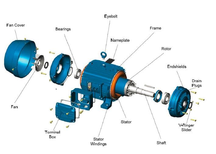
AC induction motors have other components which, together with the stator and rotor, are shown in
Figure 2 below.
Figure 2: Components of an AC Induction Motor13
12
Edward J. Thornton and J.Kirk Armintor, 2003, “The Fundamentals of AC Electric Induction Motor Design and Application”,
Proceedings of the 20th International Pump Users Symposium, available at
http://turbolab.tamu.edu/proc/pumpproc/P20/11.pdf
13
Source: See Aderiano M. da Silva, 2006, “Induction Motor Fault Diagnostic and Monitoring Methods”, Master thesis, p.15
available at http://povinelli.eece.mu.edu/publications/papers/dasilva.pdf
15APEC-CAST Motor Repairs Project
Final report - Task 1: Existing and Best Practices in Motor Repair
Motors do fail during their lifetime, and most motor failures are due to mechanical, electrical and
misapplication causes. A major energy research consortium study conducted in 1985 covering 6,000
utility industry motors revealed that 53 percent of motor failures are due to mechanical factors14, the
largest of which are associated with bearing failures (41 percent). Stator-related, rotor-related and
other mechanical failures account respectively for 37 percent, 10 percent and 12 percent of problems.
In conclusion, the primary cause of motor mechanical failure is a bearing problem, which can be
caused by any combination of contamination, lubrication, improper assembly, misalignment, or
overloading.
With regard to electrical causes, they are mainly associated with winding failures, mostly due to poor
ventilation and excessive winding temperature increases caused by overload conditions. Other factors
which can also contribute to winding failures are supply voltage variation, improper or poor electrical
connections, vibration and insulation contamination. Sometimes, electrical failures also occur in
motors because of misapplication, which is the failure to correctly match a motor’s characteristics with
the load requirements of the driven equipment (e.g. starting torque requirements).
Based on the prevalence of failure modes in electric motors and the potential effect of each failure
repair methods on the repaired unit efficiency, the study will primarily focus on three types of failure: a)
stator winding failures with lamination damage, b) stator winding failures without lamination damage
and d) rotor failures. Bearing failure has not been covered, as this is not a significant issue for motor
efficiency improvement or degradation.
For the previously mentioned failures, the motor owner always faces the choice of either repairing or
replacing the failed unit with a new motor. The decision will depend, among other things, on the
profitability of the chosen solution and the timing to proceed with the repair or the purchase of the new
unit. The building user or plant owner will often make this decision based on the impact of the repair or
procurement delay on its production, building operation schedule or agricultural activities. Therefore,
the study will cover the following repair practices:
› Rewinding practices (winding removal, rewinding configuration and modification, impregnation,
etc.)
› Lamination repair or replacement
› Rotor repair or replacement
3 REVIEW OF PRACTICES IN MOTOR REWINDING AND
REPAIR
14
Edward J. Thornton and J.Kirk Armintor, 2003, “The fundamentals of AC Electric Induction Motor Design and Application”,
Proceedings of the 20th International Pump Users Symposium, available at
http://turbolab.tamu.edu/proc/pumpproc/P20/11.pdf
16APEC-CAST Motor Repairs Project
Final report - Task 1: Existing and Best Practices in Motor Repair
Rewind and repair practices can adversely affect motor efficiency. This section reviews existing and
best practices in motor repair in the countries covered by the study.
3.1 POOR PRACTICES DURING AC ELECTRICAL MOTORS REPAIRS
A lack of know-how, improper tools or poor-quality material used by repair entities have resulted in a
situation where motor repair is not optimized with a view to maximize motor efficiency in most
developing countries. Based on a literature review and the experience of the ABB Research and
Development (R&D) unit in motor repair practices, the existing poor practices that decrease motor
efficiency are summarized in the table in Appendix II.
3.2 BEST PRACTICES IN MOTOR REWIND/REPAIR
There are motor repair industry specifications and quality assurance programs that summarize the
best practices from the electric motor repair industry. These include the Electrical Apparatus Service
Association (EASA) specifications and the motor repair specifications of the Consortium for Energy
Efficiency (CEE).
Regarding quality assurance programs, they include the well-known EASA-Q, created by the EASA to
help its members implement ISO 9001 quality system standards, and the SKF15 Certified Rebuilder
Program16 which periodically audits motor service centers and focuses on training motor shop
personnel on the aspects of bearing failure and replacements as well as root cause analysis about
motor failures. Others quality assurance programs include the Green Motor Initiative (GMI) and the
Proven Efficiency Verification (PEV) program developed by the Green Motors Practices Group
(GMPG) and the private firm Advanced Energy, respectively.
The most common best practices recommended by those organizations are summarized below. A
detailed discussion of the EASA and GMPG recommended best practices in motor rewind/repair as
presented in Appendix II.
3.2.1 Rewind/Repair
According to best practices recommendations issued by the repair industry, EASA, and by the GMPG,
in all cases where rewind/repair is called for, electric motor repair facilities should follow specific
procedures to maintain the efficiency of the rewound/repaired motor. This includes:
› Record winding data prior to winding removal to reproduce the winding initial configuration. Only
rewinding data related to winding connections can be obtained without removing the windings.
15
SKF stands for Svenska Kullagerfabriken in Swedish.
16
Electric Motor Rebuilding on SKF website at http://www.skf.com/group/index.html?contentId=687952
17APEC-CAST Motor Repairs Project
Final report - Task 1: Existing and Best Practices in Motor Repair
Details concerning the number of turns, wire size, the number of parallels and coil pitch are
obtained during the process of winding removal.
› Perform a core loss test before and after rewind/repair. Core losses can be measured in a
dismantled motor, using a flux loop test.
› Avoid lamination damage when removing the winding.
› During the new winding installation, ensure that no mechanical modifications or changes are
made to the conductor’s length and cross-sectional area as designed by the original
manufacturer
› Perform mechanical repair according to manufacturer specifications, if available. Mechanical
repair include shaft checking for wear, cracks, scoring and straightness, as well as repair related
to bearings.
3.2.2 Rotor Replacement
The repair industry has not issued specific recommended best practices regarding the replacement of
an electric motor rotor with a new one. Nevertheless, when worn rotor bars are replaced, a common
best practice recommendation is to replace them with bars made from the same materials used in the
original design. Also, one of the considerations in trying to reduce overall loss in electric motors is to
replace the aluminum rotor with a copper rotor during a repair activity. In fact, because the electrical
conductivity of copper is nearly 60 percent higher than that of aluminum, the I2 R losses in the rotor
are substantially lower when aluminum is replaced by copper as the conductive material of a squirrel
cage structure. Studies conducted in the United States suggest that electric motors fitted with copper
rotors have, on average, an overall energy loss of 14 percent lower and nameplate efficiency at least
one percent higher than those fitted with aluminum rotors.17 This trend is confirmed by the results (see
Appendix V) obtained by the simulations of the International Copper Association (ICA) as described in
Section 4 below. Replacing an aluminum rotor by a copper rotor has the potential to increase the
repaired motor efficiency compared to its nominal specification, but such a practice is contingent on
the availability of a copper replacement rotor from the manufacturer (or built by the shop).
3.2.3 Motor Replacement Criteria
Sometimes, repair shops do suggest replacing a failed motor if repair alternatives appear to be
uneconomical. However, the repair/replace decision is handled differently by service shops,
depending on their capabilities. Some shops settle on a fixed power rating (kW or HP) above which
they prefer repairing a failed motor instead of suggesting a replacement option to their clients. Other
variables such as the availability/quick delivery of the replacement motor, the number of times the
failed motor has been repaired and replacement motor efficiency are also considered.
17
D. J Van Son et al, “Development of the Copper Motor Rotor: Manufacturing Considerations and Motor Test Results”
18APEC-CAST Motor Repairs Project
Final report - Task 1: Existing and Best Practices in Motor Repair
Software tools have been developed, as part of education and technical assistance programs, to help
end-users and service providers base repair/replace decision on detailed economics, including
payback and life cycle costs, of both repair and replacement options. One of the most popular motor
life cycle cost software tools employed to make a repair/replace decision is Motor Master, which is
distributed free of charge by the U.S. Department of Energy (DOE). This tool is a data management
application with which users can compare the cost of repair with the cost of replacement for industrial
motors under any operating conditions and for any utility rate.18
3.3 SUMMARY OF REWIND/REPAIR PRACTICES IN SURVEYED
COUNTRIES
This section describes the major findings of the survey on current repair techniques based on
information19 collected at repair shops during in-person interviews conducted by native-speaking
experts in China, Japan, New Zealand, Vietnam and the United States. Participating shops were
recruited based on their size (large, medium and small). A large-size shop was defined as one with
more than 50 employees, a medium-size shop as a shop with 20 to 50 employees, and a small-size
shop has fewer than 20. The questionnaire and the summary of answers on repair techniques are
presented in Appendix III and Appendix IV, respectively. The detailed answers to the questionnaire will
be used as input into the efficiency loss model developed as part of this mandate. Table 1 shows of
number of shops by size surveyed in each country.
Table 1: Shops by Size Surveyed in Each Country
New
Size of Shop Surveyed China Japan US Vietnam
Zealand
Number of Small Shops 4 7 3 3 4
Number of Medium Shops 4 2 7 3 2
Number of Large Shops 2 1 0 1 2
Total 10 10 10 7 8
3.3.1 Rewind/Repair Techniques in Five Surveyed Countries
This section analyzes rewind/repair techniques used by service shops in the five surveyed countries.
Winding removal and stator core testing
The survey findings suggest that shops use different methods to remove winding. None of the shops
surveyed use chemical stripping, a method that has probably been phased out over time for Health,
Safety and Environment reasons. Approximately 40 percent of shops in Vietnam remove windings
18
http://www.copper.org/environment/sustainable-energy/electric-motors/case-studies/a6141/a6141.pdf (September 24,
2013)
19 19
See Section II of the survey form presented in Appendix III for information about repair techniques.
19APEC-CAST Motor Repairs Project
Final report - Task 1: Existing and Best Practices in Motor Repair
manually, which is the least technically advanced technique and likely results in higher efficiency
losses in the repaired units. A far greater percentage of shops (approximately three quarters) in China
use the “Mechanical stripping by cold process” method than in any other countries. One possible
explanation for this difference is that the cold process method is significantly more labor intensive than
other processes and may not be financially viable in countries where the wage of the workers is
higher. In all countries surveyed, a larger percentage of medium-sized shops use burn out ovens
compared with large-sized and small-sized shops. The use of a burn out oven is a standard practice
among EASA member shops and also helps reduce the time to repair. Ideally, a winding removal
procedure in a burn out oven must be followed by a stator core test. Surprisingly, fewer shops
surveyed in the United States test stator cores compared with those in other countries, even though all
shops in the United States use burn out ovens. All Chinese and Vietnamese shops reported testing
stator cores before repair.
Measuring burn out oven temperature
This practice refers to process control. If the temperature in a burn out oven is not controlled, then
there is a high probability that the stator core lamination insulation gets overheated and damaged. It is
observed that slightly less than one third of small shops do not measure oven temperature; whereas,
only few large and medium shops do not control oven temperature. It is likely that the cost of the
controls and the awareness of the effects of high temperatures in the stator core during burn-out
contribute to this observation.
Determining if stator lamination needs repair
As part of good quality motor rewind practices, shops examine stator lamination for evidence of
damaged or missing components and repair any defects revealed during inspection. Testing the stator
core with appropriate test equipment is associated with good practice, while performing a visual
inspection is associated with bad practice in motor rewind/repair. Approximately two thirds of all shops
visually inspect machines to determine if stator lamination needs repair. This is not surprising, as
visual inspection is the first level check to look for obvious damage. A large majority (more than two
thirds) of shops in all countries except China use this method along with other methods. Shops in the
United States use the widest variety of methods while those in China use only a few methods. None of
the shops surveyed in New Zealand use a commercial core loss tester. This is more likely to be a
matter of awareness or local industry culture than technical capability. Shops are probably more
focused on recurrent failures than on excessive core losses. Recurrent failures are connected with
localized hot spots, and they are identified more easily with the core loop flux test, which only requires
inexpensive test equipment. Three shops (one in New Zealand, one in the United States and one in
Japan) use advanced equipment for testing. These shops rely on ‘thermal imaging’, ‘infra-red
scanning’ and ‘sound inspection’ techniques, respectively, for motor inspection.
Thermal imaging or infrared scanning is used while performing the core flux loop test. The use of
measurement tools such as these help decide whether a stator core with hot spots is acceptable or
20APEC-CAST Motor Repairs Project
Final report - Task 1: Existing and Best Practices in Motor Repair
not. The use of “sound” or magnetic noise tests are used to indicate looseness of the stator core (not
necessarily the presence of hot spots or insulation damage) and are seldom deployed.
Method to repair lamination damage
In case any defect has been detected in the iron core, and before proceeding with the rewind/repair, it
is best practice to correct the defect by either: grinding and de-burring the lamination core plate;
replacing removed laminations with equivalent material or applying the chemical inter-laminar re-
insulation process or applying mica between the lamination. It is important to note that the existing
material should be known by testing its chemical and physical properties.
All large shops surveyed reported repairing lamination damage, whereas approximately one fifth of
small and medium shops reported that they do not generally repair lamination damage. The most
popular method (about half of all shops) is to grind and separate the damaged lamination. The method
does not involve removal of laminations and is the most cost-effective method. Grinding is the most
popular way to remove ‘drag’ or ‘flash’ in the damaged area. None of the shops in Vietnam use the
‘grinding’ method, likely due to lack of awareness. Similarly, none of the shops surveyed in Japan
reported replacing defective laminations, probably due to difficulty in obtaining replacement stampings.
A far lower quantity of shops in Japan reported using the ‘remove laminations, stagger and re-stack
the same or new laminations’ repair method as compared with shops in other countries. Although this
method of restacking a stator core is the most reliable, it is the most labor-intensive. Shops in the
United States 1) use the widest variety of methods and 2) always report repairing lamination damage.
This is evidence of better repair practices among those shops. Finally, medium-sized shops use the
widest variety of methods as compared with small and large shops.
Change in copper size
During a rewind procedure, it is best practice to ensure that the new copper-conductor size is identical
to the original one. Also, it is possible to change the size by increasing the conductor cross-sectional
area to enhance motor efficiency. None of the shops in China reported changing copper size as
compared with more than half of shops in all the other countries combined. Quite probably, this is
related to the local repair culture, where Chinese shops probably focus on exact duplication of winding
which is a simple process without having to redesign the winding.
Replacement wedges
Magnetic wedges, if not designed and used correctly, can lead to reliability problems. Shops are likely
to replace them with non-magnetic wedges to avoid recurrent failures. Also, there is a lack of
awareness about the benefits of using magnetic slot wedges.
21APEC-CAST Motor Repairs Project
Final report - Task 1: Existing and Best Practices in Motor Repair
An approximately equal percentage of shops use magnetic and non-magnetic wedges to replace
magnetic wedges. In China, the large and medium shops use non-magnetic wedges, while a majority
of the small shops use magnetic wedges.
Repairing rotor windings
Rotor windings consist of rotor bars and short-circuiting rings. All shops in the United States replace
damaged rotor windings, and it is the prevalent practice in other countries’ shops (more than two-
thirds reported replacing damaged rotor windings). Among the large shops, none of the Chinese
shops reported following this practice but this may be due to the small sample interviewed. All medium
sized shops reported replacing rotor winding. Approximately 15 percent of all shops replace the rotor
outright when the rotor winding is damaged.
3.3.2 Availability of Tools and Equipment in Repair Shops
Use of certain tools and equipment allows electric motor repair shops to perform a high quality
rewind/repair, thereby either maintaining or enhancing motor efficiency. Taken as such, the absence
of the tools and equipment could be associated with bad repair practices.
Usage of tools
The survey considered some tools which are presented in the table below, along with the repair
process they are associated with. Except a bearing oil bath, the absence of these tools in a repair
shop is associated with bad practice rewind/repair. Bearing oil bath is an old tool; hence, its presence
in a repair shop is associated with a bad practice.
Table 2: Tools Considered in the Survey
Repair Process Tool
Bearing/pulley pullers
Rotor removal Single gantry crane
Two gantry cranes
Record winding data Micrometer screw gauge
Semi-automatic coil winding machine
Rewinding
Crimping tool
Vacuum pressure impregnation (VPI) system
Impregnation
Varnish dip tank (When VPI is not used)
Bearing/pulley pullers
Bearing assembly during reassembly Bearing induction heaters
Bearing oil bath
22APEC-CAST Motor Repairs Project
Final report - Task 1: Existing and Best Practices in Motor Repair
Among all shops in the surveyed countries, bearing oil bath and VPI system are the least common
tools followed by two gantry cranes, while micrometer gauges are the most common tool. It is further
observed that U.S. shops possess the widest variety of tools, while Chinese shops possess the
smallest variety of tools. The main trends observed are summarized as follows:
› Large majorities (80 and 100 percent respectively) of shops in China do not possess
bearing/pulley pullers and two gantry cranes
› Not unexpectedly, all shops possess single gantry crane
› None of the Japanese shops possess crimping tool
› Semi-automatic coil winding machines are far more prevalent in large and medium shops than in
small shops
› More than 90 percent of small shops do not possess a VPI system. To perform resin
impregnation, a shop must ideally have either a varnish dip tank or a VPI system which is a very
expensive piece of equipment. There are other methods of impregnation such as spray or pour
methods, but these are not favorably compared with VPI or Varnish Dip methods as the VPI
system allows much better deposition of varnish.
With regards to shop size, large shops possess a wider variety of tools as compared with small and
medium shops. Furthermore, it is observed that slightly lower than one third of the shops have none of
the tools mentioned in the above table.
To conclude, it is interesting to observe the phasing-out of old methods for bearing heating (in oil
baths) and the reliance on the newer induction heating methods. In fact, based on a review of
literature and the knowledge of the study team, the old methods were used in the past and the survey
has found a decrease in the prevalence of these old methods. This is certainly an indication of
adoption of better repair practices by shops.
23APEC-CAST Motor Repairs Project
Final report - Task 1: Existing and Best Practices in Motor Repair
Usage of equipment
The survey also looked at the possession of a certain amounts of equipment in repair shops. The
equipment presented in the table below is associated with good quality electric motor repair.
Table 3: Equipment considered in the survey
Repair Process Equipment
Record winding data Winding resistance meter
Surge comparison tester
Surge comparison tester
Winding resistance meter
Rewinding Insulation resistance checker 500V
Hipot test kit (status voltage)
Thermo-graphic camera
Test panel
Stator core test
Watt meter
Power analyzer
Since stator windings are most commonly ‘replaced’ during the repair of a motor, the winding
resistance is a good and simple check to test for uniformity of the winding. It is observed that winding
resistance meter is the most commonly used equipment while power analyzers and thermo graphic
cameras are the least commonly used equipment. For example, in the United States it was observed
that small shops tend not to use thermo graphic scanning. Usage of power analyzers was not reported
as an important usage by the shops surveyed. Although one shop reported measuring efficiency, in
general most of the shops did not consider that efficiency testing was a very important factor for their
customers. The shops understand that efficiency is important, but what seemed to prevail in their
customer expectation is that the horsepower output of the motor is maintained through the repair, and
the speed of the turnaround of the motor repair/rewind. Those two factors dominated all other repair
criteria including first cost. Other trends with regards to usage of equipment are presented as follows:
› Shops in the United States use the widest variety of equipment while those in China use the
smallest variety of equipment.
› All shops surveyed in the United States and New Zealand possesses a “hipot” test kit and test
panel respectively. One of the hypotheses to explain this observed practice is customer
awareness of service processes and/or the standard expected of EASA member shops.
24You can also read