(F)LSPX ZONE 21 - Ex tb (F)LSES ZONE 22 - Ex tc - Commissioning and maintenance guide Induction motors three phase for dusty EXplosive ATmospheres ...
←
→
Page content transcription
If your browser does not render page correctly, please read the page content below
Commissioning and
maintenance guide

(F)LSPX ZONE 21 - Ex tb
(F)LSES ZONE 22 - Ex tc

Induction motors
three phase for
dusty EXplosive
ATmospheres

Reference: 5725 en - 2020.02 / c
INSTALLATION AND MAINTENANCE - LSPX-FLSPX
                                              ZONE 21 - Ex tb – LSES-FLSES ZONE 22 - Ex tc

                                                           GENERAL WARNING

These symbols            appear in this document whenever it is important to take special precautions during installation, operation,
maintenance or servicing of the motors.

It is essential that electric motors are installed by experienced, qualified and authorized personnel.

In accordance with the main requirements of EC Directives, the safety of people, animals and property should be ensured when fitting
the motors into machines.

Particular attention should be given to equipotential ground or earthing connections.

The noise levels of the machines, measured under standard conditions, complies with the requirements of the standard and does
not exceed the maximum value of 85 dB(A) pressure at 1 metre.

             The following precautions must be taken before working on any stationary device:
      • AC voltage disconnected and no residual voltage present
      • Careful examination of the causes of the stoppage (jammed transmission - loss of phase
        - cut-out due to thermal protection - lack of lubrication, etc.)

            Electric motors are industrial products. They must therefore be installed by qualified, experienced and
 authorized personnel. The safety of people, animals and property must be ensured when fitting the motors into machines
 (please refer to current standards).

Personnel likely to intervene on electrical installations and equipment in explosion risk areas shall be trained and authorized
specifically for this type of equipment.
Indeed, knowledge is required about the risks specific to electricity, but also those due to chemical properties and physical
characteristics of the products used in the installation (gas, vapours, dusts), as well as the environment in which the equipment
operates. These elements condition the risks of fire and explosion.

More particularly, he/she must be informed and aware of the reasons for particular safety instructions in order to observe them. For
example:
- never open when live,
- do not open when live if a dusty explosive atmosphere is present,
- do not repair in live conditions,
- do not manoeuvre under load,
- wait a few minutes before opening,
- refit the gaskets to guarantee sealing.

      Before commissioning, check that the information shown on the nameplate is compatible with the explosive
 atmosphere that is present and with the zone where used.

NOTE:
LEROY-SOMER reserves the right to modify the characteristics of its products at any time in order to incorporate the latest technological
developments. The information contained in this document is therefore liable to be changed without notice.
                                                    Copyright 2018: LEROY-SOMER MOTORS
                                                   This document is the property of Leroy-Somer.
                                          It may not be reproduced in any form without prior authorization.
                                        All brands and models have been registered and patents applied for.

2                              Maintenance and service guide - LSPX-FLSPX ZONE 21 - Ex tb – LSES-FLSES ZONE 22 - Ex tc
                                                                                                    5725 en - 2020.02 / c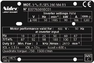
INSTALLATION AND MAINTENANCE - LSPX-FLSPX
ZONE 21 - Ex tb – LSES-FLSES ZONE 22 - Ex tc
Dear Customer,
You have just acquired a LEROY SOMER safety motor.
These motors benefit from the experience of one of the largest manufacturers in the world, using state-of-the-art technologies –
automation, specially selected materials and rigorous quality control. As a result, the regulatory authorities have awarded our motor
factories ISO 9001, Edition 2015 international certification.
We thank you for making this choice, and would ask you to read the contents of this manual.
By observing a few essential rules, you will ensure problem-free operation for many years.
LEROY-SOMER MOTORS
EU DECLARATION OF CONFORMITY OF USE AND OF INTEGRATION
Process: POC2 New product development control No. Q 0 1 T 5 0 0 Process: POC2 New product development control No. Q 0 1 T 5 0 1
Rev.: A of: 10/04/2019 Page: 1 / 1 Rev.: A of: 09/04/2020 Page: 1 / 1
EU DECLARATION OF CONFORMITY AND OF INCORPORATION Cancels and replaces: Cancels and replaces:
Beaucourt Beaucourt EU DECLARATION OF CONFORMITY AND INCORPORATION
plant FLSN and FLSES motors /
plant
/
Doc type: Q06T002 Rev F of 19/02/2018 Doc type: Q06T002 Rev F of 19/02/2018
We, Constructions Electriques de Beaucourt (CEB), 14, Rue de Dampierre, 90500 BEAUCOURT, France, (a company of the Nidec / Leroy-Somer We, Constructions Electriques de Beaucourt (CEB), 14, rue de Dampierre, 90500 BEAUCOURT, France, (a company of the Nidec / Leroy-Somer
Holding SA group, boulevard Marcellin Leroy, CS 10015, 16915 ANGOULEME cedex 9, France) declare, under our sole responsibility that the Holding SA group, boulevard Marcellin Leroy, CS 10015, 16915 ANGOULEME cedex 9, France) declare, under our sole responsibility that the
following products: following products:
FLSN type induction motors (“ec” protection mode) and Induction Motors type FLSPX for use in the presence of explosive dust; “tb” protective enclosure
FLSES type induction motors (“tc” protection mode)
Bearing the following marking(s) on their nameplates: bearing one of the following markings on their nameplate:
CE 0080 II 2 D Ex tb IIIC T125°C Db IP65 (T up to 200°C) (for zone 21)
CE II 3 G Ex ec IIC T3 Gc or (T4 Gc or T5 Gc or T6 Gc) for zone 2
or CE II 3 G Ex ec eb IIC T3 Gc or (T4 Gc or T5 Gc or T6 Gc) for zone 2 if “eb” junction box
comply with the following European Directives:
or CE II 3 G Ex ec IIC T3 Gc or (T4 Gc or T5 Gc or T6 Gc) ▪ Low voltage: 2014/35/EU
+ II 3 D Ex tc IIIB T125°C Dc IP 55 or Ex tc IIIC T125°C Dc IP 65 (up to 200°C) for zone 2 and 22 ▪ RoHS 2: 2011/65/EU
or CE II 3 G Ex ec eb IIC T3 Gc or (T4 Gc or T5 Gc or T6 Gc) ▪ Electromagnetic Compatibility: 2014/30/EU
+ II 3 D Ex tc IIIB T125°C Dc IP 55 or Ex tc IIIC T125°C Dc IP 65 (up to 200°C) for zone 2 and 22 if “eb” junction box ▪ ErP: 2009/125/EC and its (EC) implementation regulation:
640/2009 and amendments (for the products concerned)
or CE II 3 D Ex tc IIIB T125°C Dc IP 55 or Ex tc IIIB T125°C Dc IP 65 (up to 200°C) for zone 22
▪ Atex 2014/34/EU
comply with the following European Directives:
Low voltage: 2014/35/EU ▪ European standards: EN 50581:2012
RoHS 2: 2011/65/EU EN 60034-1:2010; 60034-7:1993/A1:2001; 60034-9:2005/A1:2007;
Electromagnetic Compatibility: 2014/30/EU 60034-14:2004/A1:2007; 60072-1:1991; 62262:2004
ErP: 2009/125/EC and its (EC) implementation regulation: EN 60079-0:2012/A11:2013; 60079-31:2014; 60529: 2014; 62262:2004
640/2009 and amendments (for the products concerned)
Atex: 2014/34/EU ▪ International standards: IEC 50581:2013
IEC 60034-1:2017; 60034-7:1993/A1:2001; 60034-9:2005/A1: 2007;
European standards: EN 50581:2012 60034-14:2018; 60072-1:1991; 62262:2002
EN 60034-1:2010; 60034-7:1993/A1:2001; 60034-9:2005/A1: 2007; IEC 60079-0:2012/A1: 2013; 60079-31: 2013; 60529:2015
60034-14:2018; 60072-1:1991; 62262:2004 ▪ and with the types awarded:
EN 60079-0: 2012/A11:2013; 60079-7:2015; 60079-31:2014; 60529: 2014; - EU-type examination certificate: INERIS 20ATEX0011 X
62262:2004 - certificate of conformity: IECEx INE 20.0015X
International standards: IEC 50581:2013 issued by the Notified Body: INERIS (0080) – BP2 – Parc technologique ALATA
IEC 60034-1:2017; 60034-7:1993/A1:2001; 60034-9:2005/A1:2007; 60550 VERNEUIL-EN-HALATTE
60034-14:2004/A1:2007; 60072-1:1991; 62262:2002
IEC 60079-0:2011/A11:2013; 60079-7:2015; 60079-31:2013; 60529: 2015 ▪ the design and manufacturing requirements are covered Under the responsibility of the Notified Body INERIS (0080)
and with the types awarded: by the PRODUCT QUALITY ASSURANCE notification
- type examination certificate: INERIS 18ATEX3011 X
- certificate of conformity: IECEx INE 19.0015X This compliance permits the use of these ranges of products in a machine subject to the application of the machinery directive 2006/42/EC,
provided that they are integrated or incorporated and/or assembled in accordance with, amongst others, the rules of standard EN 60204 (all
issued by the Notified Body: INERIS (0080) – BP2 – Parc technologique ALATA sections) “Electrical Equipment of Machines”.
60550 VERNEUIL-EN-HALATTE
This equipment must be installed by a professional, liable for ensuring compliance with all installation rules, decrees, orders, laws, directives,
This compliance permits the use of these ranges of products in a machine subject to the application of the machinery directive 2006/42/EC, application memos, standards (IEC-EN 60079-14, etc.), regulations, good trade practices and any other document on the installation site. The
provided that they are integrated or incorporated and/or assembled in accordance with, amongst others, the rules of standard EN 60204 (all professional is also liable for ensuring compliance with the values indicated on the motor information plate(s), instruction manuals, installation and
sections) “Electrical Equipment of Machines”. maintenance manuals and any other document provided by the manufacturer.
Constructions Electriques de Beaucourt (CEB) cannot be held liable for non-compliance with all or part of the above.
This equipment must be installed by a professional, liable for ensuring compliance with all installation rules, decrees, orders, laws, directives,
application memos, standards (IEC-EN 60079-14, etc.), regulations, good trade practices and any other document on the installation site. The Date and signature of the Technical Department
professional is also liable for ensuring compliance with the values indicated on the motor information plate(s), instruction manuals, installation and T. PERA
maintenance manuals and any other document provided by the manufacturer. April 23rd 2020
Constructions Electriques de Beaucourt (CEB) cannot be held liable for non-compliance with all or part of the above.
Date and signature of the Technical Department
T. PERA
18th july 2019
Consulter le système de gestion documentaire afin de vérifier la dernière version de ce document.
For the latest version of this document, please access the document management system. Consulter le système de gestion documentaire afin de vérifier la dernière version de ce document.
For the latest version of this document, please access the document management system.
Maintenance and service guide - LSPX-FLSPX ZONE 21 - Ex tb – LSES-FLSES ZONE 22 - Ex tc 3
5725 en - 2020.02 / c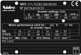
INSTALLATION AND MAINTENANCE - LSPX-FLSPX
                                                  ZONE 21 - Ex tb – LSES-FLSES ZONE 22 - Ex tc

                                       CONTENTS                                                                                                       INDEX

1 - RECEPTION .................................................................. 5                       Acceptance.......................................................................................5
      1.1 - Identification and marking.................................................... 5             Adjustments.................................................................................... 16
                                                                                                         Alarm - early warning...................................................................... 11
2 - STORAGE.......................................................................6                      Assembly.......................................................................................... 6

3 - COMMISSIONING..........................................................6                             Balancing......................................................................................... 9
      3.1 - Protocol for lubrication during commissioning ..................... 6                        Bearing housing fixing rods or screws: tightening............................ 23
      3.2 - Checking the insulation........................................................ 7            Bearing housings..................................................................... 24 - 25
                                                                                                         Belts............................................................................................... 17
4 - INSTALLATION ............................................................. 7                         Built-in thermal protection................................................................ 11
    4.1 - Position of the lifting rings.................................................... 7
    4.2 - Location - ventilation............................................................ 8           Cable gland..................................................................................... 18
    4.3 - Preparation of the fixing support.......................................... 9                  Cables.............................................................................................20
    4.4 - Coupling............................................................................. 9        Capacitors.......................................................................................24
    4.5 - Important information to be taken into consideration during                                    Connection to mains................................................................ 18 - 20
installation.........................................................................................9   Connection wiring diagrams............................................................ 19
                                                                                                         Connection..................................................................................... 20
5 - ELECTRICAL PARAMETERS - LIMITING VALUES.10                                                           Corrective maintenance...................................................................23
      5.1 - Limitation of disturbances caused by starting of motors.... 10                               Coupling .......................................................................................... 9
      5.2 - Supply voltage................................................................... 10         Coupling sleeves............................................................................. 16
      5.3 - Starting time...................................................................... 10
      5.4 - Supply with frequency inverter........................................... 10                 Digistart.......................................................................................... 12
                                                                                                         Direction of rotation.......................................................................... 19
6 - USE................................................................................10
                                                                                                         Draining off condensation water....................................................... 24
7 - SPECIAL OPERATING CONDITIONS........................12
      7.1 - Variable speed use............................................................ 13            Earth terminal.................................................................................. 19
                                                                                                         Earth........................................................................................ 12 - 19
8 - ADJUSTMENT..............................................................16                           Europe Directives........................................................................ 3 - 5

9 - MAINS CONNECTION.................................................18                                  Fan....................................................................................................8
    9.1 - Terminal box...................................................................... 18          Frequency inverter.......................................................................... 13
    9.2 - Connection to the electrical supply.................................... 18
    9.3 - Terminal block or isolator connection wiring diagram......... 19                               Handling.................................................................................. 7 - 8 - 9
    9.4 - Direction of rotation............................................................ 19           Heaters ........................................................................................... 11
    9.5 - Earth terminal and earthing................................................ 19
    9.6 - Connecting the power supply cables to the terminal block.20                                    Identification..................................................................................... 5
    9.7 - Indication of cable gland size and type for 400V rated                                         Inertia flywheel................................................................................. 16
supply voltage if drillings required without details of hole diameters                                   Insulation.......................................................................................... 7
being given...................................................................................... 21
    9.8 - Admissible number and maximum size of                                                          Lifting ring.......................................................................................... 7
holes for cable glands per “eb” terminal block.................................. 21                      Location............................................................................................ 8
    9.9 - Recommended cable temperatures................................... 21                           Lubrication - Grease nipples..........................................6 - 24 - 25 - 26
                                                                                                         Lubrication................................................................................ 25 - 26
10 - MAINTENANCE..........................................................22
      10.1 - General............................................................................ 22      Nameplate.........................................................................................5
      10.2 - Corrective maintenance: general..................................... 23
      10.3 - Safety rules...................................................................... 24       Power supply........................................................................... 10 - 20
      10.4 - Routine maintenance....................................................... 24               Power............................................................................................. 10
      10.5 - Bearing housing maintenance......................................... 25                     Protections...................................................................................... 11
      10.6 - IP Leak tightness of motor............................................... 27                Pulleys.............................................................................................17
      10.7 - Group III paints................................................................ 27
      10.8 - Troubleshooting guide..................................................... 28               Routine maintenance...................................................................... 24
      10.9 - Recycling......................................................................... 28
                                                                                                         Spare parts...................................................................................... 22
11 - LSPX MOTORS - ZONE 21........................................ 29                                    Starting............................................................................................10
   11.1 - LSPX 80 to LSPX 160 MP/LR motors.............................. 29                              Storage..............................................................................................6
   11.2 - LSPX 160 M/L, LSPX 180 MT/LR motors ....................... 31
   11.3 - LSPX 180 L, LSPX 200, LSPX 225 ST/MT/MR motors.... 33                                          Terminal box................................................................................... 18
   11.4 - LSPX 225 MG, LSPX 250 ME,                                                                      Terminal plate: tightening of nuts..................................................... 19
LSPX 280 SC/MC/MD/SD motors .................................................. 35                        Tolerances.......................................................................................16
                                                                                                         Troubleshooting...............................................................................28
12 - FLSPX MOTORS - ZONE 21..................................... 37
     12.1 - FLSPX 80 to FLSPX 132 motors..................................... 37
     12.2 - FLSPX 160 and 180 motors............................................ 39
     12.3 - FLSPX 200 and 225 MT/MS motors................................ 41
     12.4 - FLSPX 225 M to 280 motors............................................ 43
     12.5 - FLSPX 315 to 355 LD motors.......................................... 45

13 - LSES AND FLSES MOTORS - ZONE 22...................48

4                                                Maintenance and service guide - LSPX-FLSPX ZONE 21 - Ex tb – LSES-FLSES ZONE 22 - Ex tc
                                                                                                                      5725 en - 2020.02 / c
INSTALLATION AND MAINTENANCE - LSPX-FLSPX
ZONE 21 - Ex tb – LSES-FLSES ZONE 22 - Ex tc
1 - RECEPTION
This manual or its condensed version is to be given to the end user. In the event of this notice not being translated into the language of the country in which
the motor is used, the distributor is responsible for its translation and for distributing it to end users.
Products to which this manual applies may not be commissioned before the machinery in which they are installed has been declared to conform to the Directives that apply to it.
This equipment and its accessories or associated equipment must be installed by a professional, who is liable for ensuring compliance with all installation rules, decrees,
orders, laws, directives, application memos, standards (where explosive atmospheres are involved, standard IEC-EN 60079-14 as a minimum), regulations, good trade
practices and any other documents relating to the installation site. The professional is also liable for ensuring compliance with the values indicated on the motor information
plate(s), instruction manuals, installation and maintenance manuals and any other document provided by the manufacturer.
Constructions Electriques de Beaucourt (CEB) and LEROY-SOMER cannot be held liable for non-compliance with all or part of the above or with any part of
this manual.
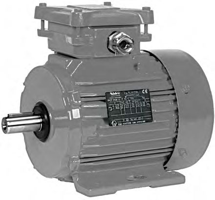
On receipt of your motor, check that it has not suffered any damage in transit.
If there are obvious signs of damage, contact the carrier (you may able to claim on their insurance) and after a visual check, turn the motor by hand to detect
any malfunction.
1.1 - Identification and marking
Check that the information shown on the nameplate is compatible with the explosive atmosphere that is present, the utilisation zone and the ambient and surface
temperatures.
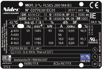
Mains supply nameplate Variable speed nameplate Quadratic torque variable speed nameplate
Definition of symbols used on nameplates:
Legal mark of equipment compliance
with the requirements of European Directives. ATEX/IECEx Protection Maximum E.P.L. Index of
Zone mode surface protection
marking level
marking temperature min
Special ATEX marking IECEx
21 II 2 D Ex tb IIIC T125° Db IP 65
:
II 2D or II 3D : ATEX/IECEx marking
Ex tb or tc : Protection mode “dust” envelope 22 II 3 D Ex tc IIIB T125° Dc IP 55
III B or III C : Equipment group
T125°C : Maximum surface temperature
Db or Dc : “dust” EPL level
0080 : Notified organisation INERIS (as II 2D)
INERIS ... X : ATEX attestation no.
IECEx INE... : IECEx certificate no.
Motor symbols: kg : Weight POLYREX EM 103 : Grease part number for
MOT 3 ~ : Three-phase A.C. motor DE : Drive end bearing bearings
FLSES : Motor type NDE : Non drive end bearing Insulated bearing : NDE : I nsulated bearing NDE
280 : Frame size g : Quantity of grease to be added per bearing side
M : Housing symbol at each re-lubrication (in g)
h : Interval in hours between re-lubrication Manufactured by CEB : Equipment manufacturer
4 : 4 poles
B3 : Operating position IP : Index of protection EAC Ex : Equipment for explosive atmospheres
No. : Serial number IK : Impact resistance index certified for Eurasia
2017 : Year of manufacture m : Maximum operating altitude cURus : Class F insulation
E068554 for USA and Canada
IM : Operating position symbol V : Supply voltage
°C : Maximum ambient temperature Hz : Supply frequency A : Vibration level code
Ins. cl. : Winding insulation class min-1 : Rated speed of rotation
S : Standard operating duty kW : Rated power H : Balancing mode code
% : Operating duty A : Rated current
d/h : Number of starts per hour cos j : Power factor NY : Starting requirements code
SF : Duty factor % : Efficiency at 4/4 load
D : Delta coupling 279 E : Plate reference
: Star coupling
IE % : Efficiency level and efficiency, Inverter settings PWM : Characteristics for setting the PWM drive to allow temperature class of motor to be met
at rated load and voltage Motor performance valid for 400V - 50Hz at inverter input : Motor performance for a voltage of 400V - 50 Hz at the
2/4 : Efficiency at 2/4 load drive input
3/4 : Efficiency at 3/4 load Duty S9 : Performances given for S9 duty
Min.Fsw : Minimum switching frequency of the drive in kHz
Nmax : Admissible maximum motor speed in rpm
PTC 140°C : PTC sensor type - temperature limit = 140°C
IOL : Admissible over-current = 1.5 x rated current
tOL : Maximum period during which over-current can occur (in secs)
tcool : Minimum duration during which the motor must be at the max of its rated current between
2 over-current events (in secs)
Quadratic torque : Type of torque: quadratic
IVIC : Pulse voltage insulation class code
Maintenance and service guide - LSPX-FLSPX ZONE 21 - Ex tb – LSES-FLSES ZONE 22 - Ex tc 5
5725 en - 2020.02 / cINSTALLATION AND MAINTENANCE - LSPX-FLSPX
ZONE 21 - Ex tb – LSES-FLSES ZONE 22 - Ex tc
2 - STORAGE 3 - COMMISSIONING
Prior to commissioning, motors should be stored: Before starting users are responsible for checking that the
- in a dry location, in their original packaging and protected equipment, the gas (and if relevant dust) group and conditions
from moisture: for relative humidities in excess of 90% the of use are compatible.
insulation may fall off very rapidly and around 100% may be
practically zero. Monitor the condition of the rust prevention In all cases, compatibility of the motor and its environ-
protection of unpainted parts. Storage conditions can be ment must be guaranteed before its installation and
between -40°C and +80°C. For storage in an environment at also throughout its life.
between -40°C and -20°C: avoid impacts with the motor
(damage due to the impact resistance of the equipment at Electric motors are industrial products.
these temperatures). THEY must therefore be installed by
For very long period storage the motor may be packaged in a qualified, experienced and authorized personnel. The
sealed envelope (e.g. thermo-welded plastic) with desiccator safety of people, animals and property must be
packs inside: ensured when fitting the motors into machines (please
- protected from large and frequent temperature variations in refer to current standards).
order to prevent condensation. During the storage periods only
drain plugs should be removed to eliminate condensation
water.
- if the area is subject to vibration, try to reduce the effect of this
vibration by placing the motor on a damping support (rubber 3.1 - Protocol for lubrication during
plate or similar). commissioning
- turn the rotor a fraction of a turn once a fortnight to prevent the
Given the “pot” storage lives stated by oil companies and the
bearing rings from becoming marked.
transport and storage conditions, the rotation systems of all
- do not remove the rotor locking device (if there are roller
motors must be subject to enhanced monitoring during the first
bearings).
week of operation.
Even if the motor has been stored in the correct conditions,
The aim of this monitoring is to ensure that an oil film is formed
certain checks must be carried out before it is started up: on the bearing tracks, thus ensuring optimum operation of the
rotation system. Finally, this means that on the one hand
Greasing personnel can become familiar with the operation of the
- Motors equipped with permanently greased bearings: equipment and on the other hand allows any teething troubles
Maximum storage period: 2 years. After this time, replace the associated with the installation to be identified.
bearings.
The amount of grease indicated for re-greasing on the
- Motors equipped with bearings that can be re-greased: nameplate must be added when topping-up with grease.
Greases must not be mixed. Grease used for top-ups must be
The motor may be commissioned if the that stated on the nameplate.
Less than 2
recommendations indicated in § 3 are
years If mixed accidentally, bearing housings (or flanges) must be
followed to the letter.
removed and fully cleaned and degreased, and the bearings
must be changed.
Storage period
Bearings must be replaced and bearing
housings (or flanges) must be cleaned In specific terms, the operations to be carried out during
and degreased in order to renew the installation are as follows:
More than grease entirely, in accordance with the • Before installing the motor, top-up with grease and
2 years information shown on the nameplate rotate the motor by hand for ten or so turns.
(quantity and type of grease). • After starting the motor (10 min), top up with grease.
Replace shaft passage seals and for • After 24 hours continuous operation, top up with grease.
IP66 motors recess seals before starting.
• After an operating period of 100 to 200 hours, top up with
grease.
Greases used by LEROY-SOMER: • During this starting period (up to 50 hours operation
See nameplates. after the last top up) there must be intensive monitoring.
The bearing housing temperatures and vibration must
be measured frequently.
Warning! Do not carry out the high voltage test
on auxiliaries. This data is to be retained by operators. It represents a
database and history which will be useful for future maintenance.
In the event of the machine being re-painted, the
thickness of the coat must not exceed 2 mm and
0.2 mm for IIC group equipment. Otherwise it must be
anti-static irrespective of its thickness if the motor is II
3G and II 3D.
6 Maintenance and service guide - LSPX-FLSPX ZONE 21 - Ex tb – LSES-FLSES ZONE 22 - Ex tc
5725 en - 2020.02 / cINSTALLATION AND MAINTENANCE - LSPX-FLSPX
ZONE 21 - Ex tb – LSES-FLSES ZONE 22 - Ex tc
3.2 - Checking the insulation For all motors before commissioning:
- remove the dust from the entire machine
Throughout the period required for checking insulation, ensure - rotate the motor at no load (no mechanical load) for 2 to
that there is no explosive atmosphere present. 5 minutes, checking that there is no abnormal noise.
If there is any abnormal noise, see section 10.
Before operating the motor we
recommend checking the insulation between
phases and earth and between phases.
4 - INSTALLATION
Motors are factory-fitted with preventative advice labels 4.1 - Position of the lifting rings
which must kept legible.
Before commissioning remove condensation (see §10.4 The lifting rings are provided for lifting
- ROUTINE MAINTENANCE) only the motor. They must not be used to lift the
machine after the motor has been fitted to it.
This check is essential if the motor has been stored for longer
than 6 months or if it has been kept in a damp atmosphere. Labour regulations stipulate that all loads over 25 kg must be
This measurement must be carried out using a megohmmeter fitted with lifting devices to facilitate handling.
at 500 volts DC (do not use a magneto-electric system). The overall mass of motors can vary according to their power,
It is better to carry out an initial test at 30 or 50 volts and if the their mounting position and whether the motors are fitted with
insulation is greater than 1 megohm, carry out a second test at optional equipment. The actual weight of each Leroy-Somer
500 volts DC for 60 seconds. The insulation value must be at motor is indicated on its nameplate. The positions of the lifting
least 10 megohms in cold state. rings and the minimum dimensions of the loading bars are
If this value cannot be achieved, or routinely if the motor might given below in order to help with preparation for handling the
have been splashed with water or salt spray, or kept for a long motors. If these precautions are not followed, there is a risk of
period in a very humid place, or if it is covered with condensation, warping or crushing some equipment such as the terminal box,
it is recommended that the stator be dried for 24 hours in an protective cover or drip cover.
oven at a temperature of 110 °C to 120 °C.
If it is not possible to dry the motor in an oven: • Horizontal position
- supply the motor, with the rotor immobilised, with a
three-phase AC voltage which is 10% below the rated voltage,
for 12 hours (use an induction regulator or a step-down
transformer with adjustable points).
- or supply it with DC supply with the 3 phases in series, with a
voltage value of 1 to 2% of the rated voltage (use a separate
excitation DC generator or batteries for motors of less than A
22 kW).
- NB: The AC current must be monitored using a clamp-on
ammeter, DC using a shunt ammeter. This current must not
e 2 x Øt
exceed 60 % of the rated current.
It is recommended that a thermometer be fitted to the motor
h
frame: if the temperature exceeds 70 °C, reduce the indicated
voltage or current by 5 % of the original value for every 10 °C
difference.
While it is drying, all the motor orifices must be open (terminal
box, drain holes). Before starting replace all plugs so that the
motor exhibits the plated degree of protection. Clean the
orifices and plugs before refitting them.
Horizontal position
Type
A e min h min Øt
M
100 120 200 150 9
112 120 200 150 9
132 160 200 150 9
160 200 160 110 14
180 MR 200 160 110 14
180 L 200 260 150 14
200 270 260 165 14
225 ST/MT/MR 270 260 150 14
Warning! Since the high voltage test was carried 225 M 360 265 200 30
225 MG 400 400 500 30
out at the factory before dispatch. If it needs to be
250 MZ 270 260 150 14
repeated, this should be performed at half the standard 250 360 380 200 30
voltage, i.e.: 1/2 (2U+1000V). Check that the capacitive 225 MG 400 400 500 30
effect resulting from the high voltage test is eliminated 250 ME/MF 400 400 500 30
before connecting the terminals to ground. 280 360 380 500 30
280 SC/MC/MD/SD 400 400 500 30
315 S 310 380 500 17
315 M/L 360 380 500 23
355 310 380 500 23
Maintenance and service guide - LSPX-FLSPX ZONE 21 - Ex tb – LSES-FLSES ZONE 22 - Ex tc 7
5725 en - 2020.02 / cINSTALLATION AND MAINTENANCE - LSPX-FLSPX
ZONE 21 - Ex tb – LSES-FLSES ZONE 22 - Ex tc
Motors intended for use in the vertical position Check that the fan cover bears no impact marks.
may be delivered on pallets in a horizontal position. Blocking (clogging) the cover grille and the housing fins,
When the motor is pivoted, the shaft must under no even accidentally, will adversely affect the operation of
circumstances touch the ground as the bearings could the motor and its safety.
be irreparably damaged. With vertical operation with shaft extension downwards, it is
recommended that the motor be equipped with a drip cover to
prevent the entry of any foreign matter.
• Vertical position
It is necessary to check that the hot air is not being recycled. If
e it is, pipes must be provided for the intake of cold air and
h expulsion of hot air, in order to prevent abnormal motor
C
temperature rise.
In this case, if the air is not circulated by an auxiliary fan, the
n x ØS dimensions of the pipes must be such that the pressure losses
are negligible compared to those of the motor.
D
Installation
Possibility of additional external heat
E The motor temperature class does not take additional external
heat into account (e.g. pump circulating a hot fluid).
View from above Side view
The motor must be mounted in the position specified on
Vertical position the order, on a base which is rigid enough to prevent
Type
C E D N ØS e min* h min distortion and vibration.
160 320 200 230 2 14 320 350 Where the motor feet have six fixing holes, it is preferable to
180 MR 320 200 230 2 14 320 270 use those which correspond to the standard dimensions for the
180 L 390 265 290 2 14 390 320 motor power rating (refer to the asynchronous motors technical
200 410 300 295 2 14 410 450 catalogue) or failing this to those shown at B2.
225 ST/MT/MR 410 300 295 2 14 410 450
225 M 480 360 405 4 30 540 350
225 MG 500 400 502 4 30 500 500
250 MZ 410 300 295 2 14 410 450
250 480 360 405 4 30 540 350
250 ME/MF 500 400 502 4 30 500 500
280 S 480 360 485 4 30 590 550
280 M 480 360 585 4 30 590 550
280 SC/MC/MD/SD 500 400 502 4 30 500 500
315 S 590 - 590 2 17 630 550
315 M/L 695 - 765 2 24 695 550 B 1
355 755 - 835 2 24 755 550 B 2
* If the motor is fitted with a drip cover, allow an additional 50 to 100 mm to avoid
damaging it when the load is swung.
Provide easy access to the terminal box, the condensation
drain plugs and, if appropriate, to the grease nipples.
4.2 - Location - ventilation
Use lifting equipment which is compatible with the weight of the
Our motors are cooled in accordance with method IC 411
motor (indicated on the nameplate).
(standard IEC 60034-6) i.e. “machine cooled by its surface,
using the ambient fluid (air) flowing along the machine”.
The fan at the non-drive end cools the motor. Air is sucked in When the motor is fitted with lifting rings, they are
through the grille of a fan cover (which provides protection solely for lifting the motor and must not be used to
against the risk of direct contact with the fan in accordance with lift the whole machine after the motor has been fitted to it.
standard IEC 60034-5) and blown along the housing fins to Note 1: When installing a suspended motor, it is essential
ensure thermal equilibrium of the motor whatever the direction to provide protection in case the fixing breaks.
of rotation. Note 2: Never stand on the motor.
1/4 H min
H
The motor is to be installed in an adequately ventilated area,
where the air inlets and exits are free by a value of at least a
quarter of the frame height.
8 Maintenance and service guide - LSPX-FLSPX ZONE 21 - Ex tb – LSES-FLSES ZONE 22 - Ex tc
5725 en - 2020.02 / cINSTALLATION AND MAINTENANCE - LSPX-FLSPX
ZONE 21 - Ex tb – LSES-FLSES ZONE 22 - Ex tc
4.3 - Preparation of the fixing support Balancing
Rotating machines are balanced in accordance with standard
Installers must pay particular attention to ensuring good IEC 34-14:
preparation of the motor fixing support. - half-key when the shaft extension is marked H.
When specifically requested, balancing may be carried out:
Specific points to be observed: - no key when the shaft extension is marked N,
• All metal supports must have undergone anti-corrosion - full key when the shaft extension is marked F,
treatment. any coupling element (pulley, coupling sleeve, slip-ring, etc.)
• The design and the dimensions of the support must must therefore be balanced accordingly.
prevent any vibration being transmitted to the motor, as
well as any vibration caused by resonance. Motor with 2 shaft extensions:
If the second shaft extension is not used, in order to
• The support must be level and sufficiently rigid to conform to the balancing class the half-key or key must be
enclose any short-circuit effects. firmly fitted in its groove so that it is not ejected during
• The maximum level difference between the motor fixing rotation (H or F balancing) and to protect it against direct
feet must not exceed +/- 0.1 mm. contact.
0.1 mm max Level straight-edge
4.5 - Important information to be taken
into consideration during installation
Fixing feet position - Equipment to which this manual applies may not be
commissioned before the machinery in which it is installed has
been declared to conform to the Directives that apply to it.
- When motors are supplied by suitable electronic converters
4.4 - Coupling and/or controlled by electronic command and control devices,
they must be installed by a professional who will be responsible
Preparation for ensuring compliance with the electromagnetic compatibility
Rotate the motor by hand to detect any possible fault due to regulations for the country in which the product is installed.
handling.
- As standard the motors’ impact resistance corresponds to
Remove any protection from the shaft extension.
“low” mechanical risk, therefore they must be installed in a low
mechanical risk environment.
- All unused orifices must be blocked off using Ex threaded
plugs.
- All accessories (cable glands, plugs etc.) cited in this notice
must be of a type that is attested or certified for the group, the
application (gas and/or dust) and the temperature class which
correspond as a minimum to those for the location of the
equipment (see the information on the nameplate). They are
correctly tightened onto their support. A ‘’KLINGERSIL C-4400’’
fibre seal, for example, is placed between the cable glands, the
Drain off any condensation water that has formed inside the plugs and their support. Cable glands must be appropriate for
motor by removing the plugs from the drain holes. Before the supply cable and any auxiliary cables. The cables are
commissioning these plugs must be replaced and the motor correctly gripped in the cable glands.
must exhibit the plated degree of protection.
Fitting must comply with the requirements of their instructions
for use.
Rotor locking device
For made-to-order motors with roller bearings, remove the - The assembly of all these components must ensure the mode
rotor locking device. of protection (Ex) and the protection indices (IP, IK) specified
In exceptional circumstances when the motor has to be moved on the nameplates.
after the coupling device has been fitted, the rotor must be re-
- All threaded components must be fully tightened.
immobilized.
Maintenance and service guide - LSPX-FLSPX ZONE 21 - Ex tb – LSES-FLSES ZONE 22 - Ex tc 9
5725 en - 2020.02 / cINSTALLATION AND MAINTENANCE - LSPX-FLSPX
ZONE 21 - Ex tb – LSES-FLSES ZONE 22 - Ex tc
5 - ELECTRICAL PARAMETRES - 5.2 - Supply voltage
LIMITING VALUES The rated voltage is indicated on the nameplate.
5.1 - Limitation of disturbances caused 5.3 - Starting times
by starting of motors Starting times must remain within the limits indicated below on
To ensure preservation of the installation, any significant condition that there are 6 or less starts during one hour.
overheating of pipework must be avoided whilst ensuring that Three successive cold starts and two consecutive hot starts
the protective devices do not intervene during starting. are allowed.
Disturbances resulting in the operation of other equipment 25
connected to the same source are due to the voltage drop
caused by the current demand on starting (multiple of the
20
current passing through the motor at full load (about 7) see
LEROY-SOMER asynchronous motors technical catalogue).
Time (secs)
Even though networks are increasingly capable of allowing 15
direct starting, current demand must be reduced for certain
installations.
10
Jerk-free operation and smooth starting mean that the driven
machinery will be easier to use and have a longer operating
life. 5
5 6 7 8 9 10
Id/In
The two essential parameters for starting squirrel cage
Cold starting Hot starting
synchronous motors are:
- starting torque
- starting current. Permissible motor starting time as a function of the ratio ID / IN.
The starting torque and the resistive torque determine the
In the event of frequent or difficult startup conditions, equip
starting time.
motors with thermal protection devices (see § 6 - USE).
Depending on the driven load, the torque and current can be
altered to match the starting options of the machine and to
match the supply options.
5.4 - Supply with frequency inverter
The five essential modes are:
- D.O.L. starting, See § 7.1.
- star/delta starting,
- soft starting with autotransformer,
- soft starting with resistors,
- electronic starting.
Electronic starting modes control the voltage at the motor
terminals throughout the entire starting phase, giving very
gradual smooth starting.
6 - USE
Thermal protection devices (see § 8) and heaters
Operating Operating Switch Mounting
Type Protection provided
principle curve rating (A) Number of devices*
bimetallic strip, indirectly I
heated, with normally Installed in the
Thermal protection general surveillance
open contact (0) control circuit
on opening for non-transient
2.5 at 250 V
PTO T overloads
with cos j 0.4 2 or 3 in series
O TNF
bimetallic strip, indirectly I
heated, with normally Installed in the
Normally closed general surveillance
closed (F) contact control circuit
thermal protection for non-transient
2.5 at 250 V
PTF T overloads
with cos j 0.4 2 or 3 in parallel
F TNF
10 Maintenance and service guide - LSPX-FLSPX ZONE 21 - Ex tb – LSES-FLSES ZONE 22 - Ex tc
5725 en - 2020.02 / cINSTALLATION AND MAINTENANCE - LSPX-FLSPX
ZONE 21 - Ex tb – LSES-FLSES ZONE 22 - Ex tc
Non-linear variable R Mounted with associated
resistor,
Positive temperature relay in
indirectly heated general surveillance
coefficient thermistor control circuit
for transient overloads
PTC T 0
TNF 3 in series
Thermocouples Mounted in control panels
V
T (TINSTALLATION AND MAINTENANCE - LSPX-FLSPX
ZONE 21 - Ex tb – LSES-FLSES ZONE 22 - Ex tc
7 - SPECIALOPERATINGCONDITIONS - Earthing
The motor must be earthed in accordance with the applicable
- Installation zones regulations (protection of workers).
Our motors offer an IP 65 (or IP 55-zone 22) degree of protection An external terminal on the frame is used for effective earth
and we guarantee their surface temperature. They are intended connection of equipotential links. This terminal must be
for use in dusty explosive atmospheres of group II - Category prevented from working itself loose.
2 (IP 65-zone 21) or Category 3 (IP 55-zone 22).
- Leak tightness
- Employee safety Monitor the condition of all seals and replace them periodically
Protect all rotating devices before power-up. if necessary (Once a year at least for Ex tb motors).
If a motor is started up without a coupling device having been At the shaft passages, take care not to damage the seals in
fitted, carefully immobilize the key in its housing. contact with the keys and shoulders.
All measures must be taken to provide protection against risks After removing drain plugs, refit them in place in order to ensure
associated with rotation of components (sleeve, pulley, belts the plated degree of protection of the motor. Replace the seals
etc.). that are removed using new seals with the same characteristics.
Beware of backdriving when the motor is switched off. Clean the orifices and plugs before refitting them. Whenever
Appropriate precautions must be taken: removed it is recommended that once a year (depending on
- pumps, install a non-return valve, for example. the application) you replace seals (shaft passages, bearing
housing recesses, terminal box cover etc.) using new seals
- Thermal protection (see § 6 & 8) with the same characteristics after cleaning the components.
Motors for difficult starting conditions or with frequent starting Shaft passage seals must be fitted using the same type of
must be equipped with thermal protection. grease as the bearings.
- Heaters (see § 6) IP6X thread leak tightness (mandatory if Ex tb marking)
Heaters must only be in service when the motor is stopped and may be enhanced using grease.
cold. Recommended for use when ambient temperatures ≤
20°C. In all cases the power dissipated must ensure that the - Shock resistance
temperature classification of the motor is observed. The motor can withstand a low mechanical impact (IK 08
according to EN 50102). The user must provide additional
- Temperatures: storage and ambient
protection if there is a risk of significant mechanical shock.
Note: Ta = ambient temperatures
Note: option IK 10 may be ordered.
If the motor has been stored at a temperature below -10 °C,
heat the motor (see § 3) and turn the shaft by hand before
operating the machine. - LEROY - SOMER “Digistart” electronic starter
If the motor is to be used at a temperature lower than -25 °C, it This is micro-controlled multi-function electronic system,
must not be fitted with a sensor. It can be fitted with which is used with all squirrel-cage asynchronous three-phase
thermocouples. motors.
As standard construction, our motors are designed to operate
It ensures smooth starting of the motor with:
at temperatures between -20 °C and 40 °C.
- reduced starting current,
If Ta < -25 °C, shaft passage seals must be made of silicone and
the fan made of metal. - smooth jerk-free acceleration achieved by controlling the
If Ta < -25 °C or (and) if 50 °C < Ta ≤ 60 °C, terminal box face current in the motor.
seals must be made of silicone. After starting, the DIGISTART carries out additional motor
management functions in its other operating phases: steady
- Surface temperature state and slowing.
As standard, the maximum surface temperature of our motors - Models from 18 to 1600 A
is 125 °C with a maximum ambient temperature ≤ 40 °C. - Power supply: 220 to 700 V - 50/60 Hz
Without adaptation of the motor the maximum surface
The DIGISTART is low-cost to install, and only an additional
temperature will be:
switch and fuses are required.
• 135 °C if 40 °C ≤ Ta ≤ 50 °C
• 145 °C if 50 °C ≤ Ta ≤ 60 °C The “Digistart” electronic starter associated with the
motor must be installed outside the hazardous zone
- Connection (zones 20, 21, 22).
Particular attention must be paid to the information on the
nameplate in order to choose the correct type of connection for - Contactors - Main switches
the supply voltage. Under all circumstances contactors, main switches etc. must
When motors are equipped with one or more auxiliary be installed and connected in a panel which offers a degree of
connection boxes, it can only withstand a low risk of mechanical protection and a surface temperature compatible with the
damage, and users must provide additional protection if there installation zone, or outside the hazardous zone (zones 20, 21
is a high risk. and 22).
Similarly the protection system and the supply cables (the
voltage drop during the starting phase must be less than 3%)
are to be selected according to the characteristics marked on
the nameplate.
12 Maintenance and service guide - LSPX-FLSPX ZONE 21 - Ex tb – LSES-FLSES ZONE 22 - Ex tc
5725 en - 2020.02 / cINSTALLATION AND MAINTENANCE - LSPX-FLSPX
ZONE 21 - Ex tb – LSES-FLSES ZONE 22 - Ex tc
- Auxiliary fan In certain cases, the use of forced ventilation (where the fan is
When the motor is equipped with auxiliary or forced ventilation driven by an auxiliary motor whose type has been certified)
a device must prevent the main motor form operating in the may prove necessary. For small motors (frame height less than
absence of ventilation. 160), the standard self-ventilated cooling mode (IC411) is
nevertheless to be preferred.
- Fitting sensors or accessories
In the event that sensors (vibration sensors for example) or A device for measuring the actual speed of the motor using an
accessories (pulse generators for example) are fitted, these incremental or absolute encoder which is ATEX certified, may
must be connected in a panel. All these accessories (as well as also be installed at the rear of most of our safety motors.
the panel if it not located outside the explosive atmosphere)
must be of a type that is certified or attested for the group, the ATEX motors supplied through a frequency inverter are
application (Gas or Gas and dust) and the temperature class equipped with thermal protective devices in the winding.
which corresponds at least to that of the motor. Fitting must These must operate independently of measuring and
comply with the requirements of their instructions for use. control devices required for operation. Our derating
The sensors must exhibit an IP 65 (zone 21) or IP 55 (zone 22) tables are based on a drive supply whose switching
degree of protection at least. frequency is equal to or greater than 3 kHz.
ADAPTATION OF MOTORS
- Noise level A motor is always characterised by the following parameters,
Most (F)LSPX / (F)LSES zone 22 motors have an acoustic which depend on the design:
pressure level of less than 80 dB(A) (+/- 3dB) at 50Hz. - temperature class
The values for each motor are given in our technical catalogue. - voltage range
When the motors operate using a drive, please contact us for - frequency range
the noise levels. - thermal reserve
CHANGES IN MOTOR PERFORMANCE
When power is supplied by a drive, changes are observed in
7.1 - Variable speed use the above parameters due to certain phenomena:
- voltage drops in the drive components
7.1.1 - General - current increase in proportion with the decrease in voltage
Drive control by a frequency inverter can in fact result in an - difference in motor power supply according to the type of
increase in the machine temperature rise, due to a significantly control (flux vector or U/f)
lower supply voltage than on the mains, additional losses The main consequence is an increase in the motor current
related to the wave form produced by the drive (PWM) and the resulting in increased copper losses and therefore a higher
reduction in speed of the cooling fan. temperature rise in the winding (even at 50 Hz).
Reducing the speed leads to a reduction in air flow and hence
Standard IEC 60034-17 describes numerous good practices
a reduction in cooling efficiency, and as a result the motor
for all types of electric motor, however since this is Leroy-
temperature rise will increase again.
Somers’ area of specialist expertise, we describe the best
Conversely, in prolonged operation at high speed, the fan may
ways to deal with variable speed in the section below.
make excessive noise, and it is advisable to install a forced
The homologation conditions of our safety motors allow them
ventilation system.
to operate on frequency drives on condition that the required Above the synchronous speed, the iron losses increase
precautions are taken to ensure that under all circumstances and hence cause further temperature rise in the motor.
there is compliance with the temperature class marked on the The type of control mode influences temperature rise in the
nameplate. motor:
Drive control using a frequency inverter results in an increase - A U/f ratio gives the fundamental voltage maximum at 50 Hz
in the machine temperature rise, primarily as the result of a but requires
reduction in cooling fan speed and a supply voltage which is more current at low speed to obtain a high starting torque and
significantly lower than that of the network. Consequently a therefore generates a temperature rise at low speed when the
reduction must generally be made in the rated power of the motor is poorly ventilated.
motor. Derating tables have been produced by our design - Flux vector control requires less current at low speed while
bureau based on under-load tests on platforms, and on the providing significant torque but regulates the voltage at 50 Hz
requirements of IEC 60034-17. Depending on the application, and causes a voltage drop at the motor terminals, therefore
on the desired speed range and the torque profile of the driven requiring more current at the same power.
machine, Leroy-Somer will select the most suitable safety
motor. The drive, if of a type not designed for operation in an The temperature classification was realised with an IGBT
explosive zone, must be located in a non-explosive zone. drive supply and PWM waveform, min switching frequency
= 3kHz, U/f constant open loop.
Maintenance and service guide - LSPX-FLSPX ZONE 21 - Ex tb – LSES-FLSES ZONE 22 - Ex tc 13
5725 en - 2020.02 / cINSTALLATION AND MAINTENANCE - LSPX-FLSPX
ZONE 21 - Ex tb – LSES-FLSES ZONE 22 - Ex tc
CONSEQUENCES OF POWER SUPPLIED BY DRIVES The thermal protection devices must be connected
When power is supplied to the motor by a variable speed drive to a device which de-energises the motor when the
with diode rectifier, this causes a voltage drop (~5%). setting value is reached and before the maximum surface
Some PWM techniques can be used to limit this voltage drop temperature T° of the motor reaches the classification
(~2%), to the detriment of the machine temperature rise temperature shown on the nameplate.
(injection of harmonics of orders 5 and 7).
The non-sinusoidal signal (PWM) provided by the drive - When the motor is equipped with auxiliary or forced ventilation
generates voltage peaks at the winding terminals due to the (IC416) a device must prevent the main motor form operating
significant voltage variations relating to switching of the IGBTs in the absence of ventilation. Stopping the auxiliary motor must
(also called dV/dt). Repeated overvoltages can eventually cause the main motor to stop.
damage the windings depending on their value and/or the
- Heaters must only be supplied when there is no supply to the
motor design.
motor and the latter is cold. Their use is recommended for
The value of the voltage peaks is proportional to the supply
ambient temperatures of less than -20°C.
voltage.
This value can exceed the limit voltage for the windings which - Supply voltages and frequencies must comply with those
is related to the wire grade, the impregnation type and the stated on the motor nameplate.
insulation that may or may not be present in the slot bottoms or - The frequency range stated on the motor nameplate must be
between phases. strictly observed.
Another reason for attaining high voltage values is when - In the event of several motors being supplied by the same
regeneration phenomena occur in the case of a driving load,
drive, for safety reasons individual protection must be provided
hence the need to prioritise freewheel stops or stops that follow
on each motor outlet (e.g. thermal relay).
the longest permissible ramp.
- The specific instructions given in the specific instruction
manuals must be followed if a drive is used.
7.1.2 - Minimum recommendations
- Cable glands and components must be compatible with the
The specific instructions given in the specific instruction protection mode used for the connection portion. Alternatively,
manuals must be followed if a drive is used. In particular the with integral cables, the motor connection must be made
following minimum requirements must be observed: outside the explosive atmosphere or in a housing protected by
- Check that the drive switching frequency is 3 kHz minimum. a recognised protection method which is suitable for this use.
- Check that the motor has a second nameplate which give the - The degree of protection of the motor, of its main connection
maximum characteristics and performance levels of the motor housing and of any auxiliary connection box(es) is:
during its use at variable speed. * for zone 21: IP65 - IK08
- The reference voltage, usually 400V 50 Hz, is given on the * for zone 22: IP55 - IK08
motor nameplate. The drive must deliver a constant voltage/ The user must provide additional protection if there is a high
frequency ratio. risk.
- Programme the maximum current value as well as the min
and max frequency values shown on the second nameplate of - Variable speed
the motor into the drive. The use of these motors with a frequency or voltage inverter
- Connect all the temperature sensors present on the motor supply requires specific precautions for use:
(windings and, if relevant, bearing housings) to safety devices
which are independent of those used for operation under The reference voltage (inverter output or
normal conditions. motor input) is 400 V at 50 Hz; the drive must supply
a constant voltage/frequency to the motor.
Drives and sensor connection components must
be located outside hazardous zones (zones 0, 1, 2, The voltage and supply frequency range specified
20, 21 and 22). by the motor nameplate must be rigorously
observed.
7.1.3 - Special conditions for safe use Drives and sensor connection components must
be located outside hazardous zones (zones 20, 21
- As standard the motors’ impact resistance corresponds to and 22).
“low” mechanical risk, therefore they must be installed in a low
mechanical risk environment.
- The motor must be equipped with 3 thermal sensors (1 per
phase) placed in or on the stator connection side winding
heads (all frame sizes) and on the front bearing housing (from
frame size 355) in the following cases:
- motor supplied by frequency inverter
- motor in a sufficient, non self-ventilated airflow (IC418)
- motor adapted to no longer be self-ventilated (IC410)
- motor equipped with a backstop
- motor equipped with an auxiliary fan (IC416A) or radial
fan (IC416R)
14 Maintenance and service guide - LSPX-FLSPX ZONE 21 - Ex tb – LSES-FLSES ZONE 22 - Ex tc
5725 en - 2020.02 / cYou can also read