Valve Mechanism for Gasoline Engine with Linear Motor (Fundamental Consideration Using Electromagnetic Field Analysis)

Page created by Frances Lewis
 
CONTINUE READING
Valve Mechanism for Gasoline Engine with Linear Motor (Fundamental Consideration Using Electromagnetic Field Analysis)
Proc. Schl. Eng. Tokai Univ., Ser. E
44 (2019) 35-39
DOI: 10.18995/24343641.44.35

            Valve Mechanism for Gasoline Engine with Linear Motor
 (Fundamental Consideration Using Electromagnetic Field Analysis)
                                                                   by

                            *1
     Yukinao SATO                , Takayoshi NARITA *2 Hideaki KATO *3 , Helmut Takahiro UCHIDA *4
                                            and Yoshihito MATSUMURA *5

                                          (Received on Apr. 5, 2019 and accepted on Jul. 4, 2019)

                                                                Abstract
            Recently, high efficiency of an automobile engine is demanded from the viewpoint of energy saving.
       Therefore, the authors designed a linear motor capable of the engine valve action, and the authors proposed a
       valve system that can improve combustion efficiency and reduce pumping loss by arbitrary valve lift and valve
       timing. In this study, the authors derived the target thrust in this basic study and aimed for optimization of the
       electromagnetically driven valve system (EDVS) design. In the analysis of a model with one coil and two
       permanent magnets (PMs), stable thrust could not be obtained. A model with three coils and three PMs, change
       of thrust was observed by the respective arrangement of the coil and PM. The condition with most stable and
       highest thrust with respect to the change of obtained stroke was found, when the upper surfaces of the three
       coils are present near the halfway position of each PM, when the valve is fully opened.

       Keywords: Linear motor, Air-pass system, Gasoline engine, Position arrangement, Electromagnetic field
       analysis

                        1. Introduction
                                                                          cause valve action, without the different expected valve
     Recently, high efficiency of an automobile engine is                 timing corresponding to the camshaft.
demanded from the viewpoint of energy saving. Items that                       On the other hand, unequal pitch springs changing the
are rapid combustion, increase in the amount of intake air and            natural frequency are used to eliminate surging of coil spring
reduction in friction loss should achieve high efficiency, and            in the prior art, but the occurrence of resonance in the high
various studies, such as a study on the thermal efficiency of             rotation range has not yet been solved. To solve this problem,
                                   1)
diesel engines by Yoshida, et al. and a study on piston ring              a system for valve action by using a linear motor without a
as friction ross by Tanihata, et al. 2), are being conducted. To          cam mechanism has been proposed. Electromagnetic valve
increase the amount of intake air, improvement of charging                designs   have   also     been   carried   out   by   automobile
efficiency and high rotation are required. Particularly, it is            manufacturers such as GM and Honda 3,4). In addition, control
said that valve springs are a major factor hindering                      of valves using electromagnetic motors has been confirmed
high-speed rotation. In general, mechanisms including cam                 by Okazaki et al. 5), although it is limited to the conditions in
and valve springs are used for the valve train of the                     motorcycle engines. In this method, a disk shape is added to
conventional engine. In this case, the resonance of the valve             the shaft portion of the valve, electromagnets are installed on
spring by the influence of vibration from the engine would                the disk’s upper and lower surfaces, and the attraction force
                                                                          acting on the disk and the electromagnet (EM) is taken as the
*1 Graduate Student, Course of Mechanical Engineering
*2 Assistant Professor, Department of Prime Mover                         driving force of the valve. However, the gap between the
   Engineering                                                            electromagnet and the disk greatly changes due to the
*3 Junior Associate Professor, Department of Prime
   Mover Engineering                                                      operation of the valve, the thrust characteristic becomes
*4 Junior Associate Professor, Department of Precision                    nonlinear, and therefore it is considered as difficult to
   Engineering                                                            precisely control the positioning. On the other hand, Uchida
*5 Professor, Department of Nuclear Engineering

                                                                   ―35―
Vol. XLIV, 2019
Yukinao SATO, Takayoshi NARITA Hideaki KATO, Helmut Takahiro UCHIDA and Yoshihito MATSUMURA

                                                                               GM and Honda. In addition, control of valves using
                                                                               electromagnetic motors is confirmed by Okazaki et al.,
                                                                               although it is limited for the conditions of motorcycle engines.
                                                        EDVS                   Figure 1 shows a combination of an engine model and an
                                                                               electromagnetic valve. The premixed gas flows from the
                                                                               intake port and the combustion gas is discharged from the
                                                                               exhaust port. Engine valves are installed to open and close
                                                                               these orifices. The engine valve is connected to the EDVS at
                                                                               the cylinder head part, opening and closing the orifice by
                   Intake
                                                       Exhaust                 driving it up and down.
                    port
                                                        port

              Combustion                                                       2.2 EDVS target capability
               chamber                                                              Because the thrust required for opening and closing the
                                                                               valve varies greatly depending on the engine speed and
               Fig. 1 Electric valve system for gasoline engine.               displacement, it is important to set a detailed target thrust
                                                                               according to the specification of the installed engine.
         6)
et al.        proposed an electromagnetic valve using a coil and a             Therefore, we assume an engine using a relatively high
permanent magnet, whereby their shapes were optimized,                         revolution range as usually used for motorcycles. Under such
indicating that a constant thrust can be generated even when                   conditions, if the valve lift amount is 10 mm, the maximum
the valve is displaced. However, these studies have focused                    revolution speed is 12,000 rpm, the crank rotation is 2
on solving the surging phenomenon of the valve spring, and                     revolutions per crank, and the operating angle is 250 degrees,
studies have not been conducted using the point that the valve                 the acceleration required for valve operation is 7.90×10 3 m/s 2.
lift amount and timing can be changed positively for                           Furthermore, because the diameter of the intake valve needs
efficiency improvement.                                                        to be larger than the exhaust valve. If the mass of the intake
      Therefore,  this  research            group    proposes      an          valve is assumed to be heavy, for example 25 g, we
electromagnetic valve that achieves the desired thrust by                      calculated a force of 190 N from the equation of motion.
laminating simple structure modules. As an initial study,                      Therefore, we set the target thrust in this study as 200 N with
electromagnetic field analysis was performed on a linear                       a certain margin.
motor for driving a valve, and output characteristics of an
electromagnetically driven valve system were studied.                              3. Study on EDVS Basic Model by Magnetic Field
                                                                                                          Analysis
   2. Electromagnetically Driven Valve System (EDVS)
                                                                               3.1 Outline of analysis model
2.1 EDVS                                                                            We optimized EDVS shape for setting in a practical
     EDVS moves the intake and exhaust valves of the                           engine to achieve the target thrust. We modeled the
engine by solenoids consisting of coils, magnets and iron                      electromagnetically-driven valve and analyzed the magnetic
cores. EDVS fundamentally solves valve surging, valve-jump                     field. In this chapter, we analyzed the basic model consisting
and valve bounce generated in a system using a conventional                    of one of the simplest coils and two PMs as the initial stage.
valve spring. Additionally, though valve lift amount and                       General-purpose 3D CAD software was used for modeling,
valve timing fixed conventional engine, EDVS can realize                       and we evaluated thrust characteristics for a drive valve with
variable valve lift and valve timing in a wide range and                       electromagnetic field analysis software JMAG Ver. 11.1
without steps, by using an electromagnetic valve. This                         (manufactured by JSOL Corporation) for electromagnetic
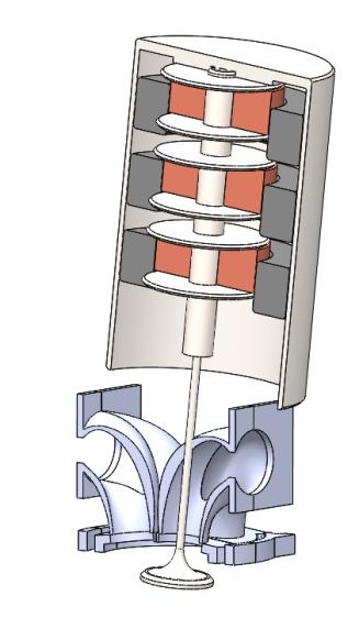
stepless variable valve lift and valve timing makes it possible                field analysis. Figure 2 shows the model used in this analysis.
to control the amount of air inflow without a throttle valve,                  Figure 2 shows a cross-section of the basic EDVS model.
and it is possible to eliminate the resistance of the intake air               Coil, inner yoke and valve are collectively referred to as
by the throttle valve. Because parts such as a camshaft and a                  mover, PM and case are referred to as stator in Fig. 2. The
throttle valve are not required according to the above                         layout of the stator and mover shown in the figure is in the
characteristics, it is also possible to reduce weight. As                      state that the stroke of the valve is 0 mm, and the valve is
mentioned in Chapter 1, electromagnetic valve designs have                     completely closed at this time. Furthermore, the direction that
also been carried out by automobile manufacturers such as                      the valve opens is positive. In addition, when determining the
                                                                               dimensions of the analytical model, the number of coil turns

                                                                        ―36―                          Proceedings of the School of Engineering
                                                                                                                     Tokai University, Series E
Valve Mechanism for Gasoline Engine with Linear Motor
                                    (Fundamental Consideration Using Electromagnetic Field Analysis)

                                                                                                     30

                                                                                                     20

                                                                                Input current (A)
                                                                                                     10

                                                                                                      0
                                           Permanent
                                            magnet                                                  -10
         Inner yoke                N         (PM)
                                                                                                    -20
                                   S
        Coil                                  PM                                                    -30
                                            distance                                                      0      2       4      6        8     10
                                                                                                                     Valve position (mm)
                                   S
          Case
                                   N                                       Fig. 3 Analytical condition of coil current in each stroke.

                   Fig. 2 Basic analysis model.                                                     150

                                                                                                    100

                                                                                Static thrust (N)
      Table 1 Materials of elements in analysis model.
                                                                                                    50
                 Coil bobbin   YEP-B(Permalloy)
                   Valve            S45C                                                             0
                     Coil          Copper
                                                                                                    -50
                    Yoke       YEP-B(Permalloy)
                  Magnet        NEOMAX-P11                                                  -100

                                                                                            -150
         Table 2 Dimensions of basic analysis model.                                                      0      2       4       6       8         10
                                                                                                                         Distance (mm)
                        Case outer diameter φ45.0 mm
           Case                 Height          60.0 mm                                                   Fig. 4 Analysis result of basic model.
                                Weight           2531.0 g
                           Inner diameter       φ30.0 mm
                                                                           3.2 Analysis conditions
            PM             Outer diameter       φ41.0 mm
                               Thickness        15.0 mm                         We obtained the thrust force characteristic generated in
                           Inner diameter       φ3.4 mm                    the movable part when a direct current of 20 A was applied to
        Inner yoke         Outer diameter       φ7.6 mm                    the electromagnet. At that time, the mover moved 1 mm at a
                                Height          50.0 mm                    time and lifted the valve to 10 mm. After that, the valve was
                           Inner diameter       φ12.0 mm
                                                                           similarly returned to the completely closed state (original
                           Outer diameter       φ48.0 mm
                                                                           point). We obtained the thrust characteristics during one
            Coil           Number of turn        200 turn
                          Diameter of wire       2.0 mm                    round trip. The wire diameter of the coil at the time of
                                Height          50.0 mm                    analysis was 2.0 mm, and the number of turns was 200.
       Valve head          Outer diameter       φ28.0 mm                   Therefore, the current to be applied was set to 20 A with
       Valve shaft              Height          133.0 mm                   reference to JSIA 302 of the Japan Switchboard & Control
                                                                           System Industry Association. Figure 3 shows the applied
was derived from the following equation.                                   current to the displacement of the valve during analysis.
                                                                           When a positive current was passed, the direction of the
                               t d
                       Nt =     −                            (1)           current flowing through the coil was set as shown in Fig. 2.
                               d 2                                         The direction of the magnetic pole of the PM is as shown in

                               2(h − d )                                   the same figure. First, 20 A was applied at the time of
                      Nh =                                   (2)           opening direction, and -20 A was applied during the closing
                               d 3 +1                                      direction.
where, N t is the number of turns in the thickness direction, N h
is the number of turns in the height direction, t is coil                  3.3 Analysis result
thickness [mm], h is the coil height [mm], and d is the                         Figure 4 shows the analysis results of the proposed
diameter of the winding including the coating [mm]. Table 1                model. We confirmed that the EDVS can generate thrust of
shows materials for each part of the model and Table 2 shows               about 20 N and the change in the thrust is small when the
dimensions of the model. In addition the target thrust was 130             valve is displaced. However, generated thrust is not achieved
N from the previous research by Uchida et al. 1).                          target thrust. Therefore, in next section, a method of
                                                                           improving thrust is investigated.

                                                                    ―37―
Vol. XLIV, 2019
Yukinao SATO, Takayoshi NARITA Hideaki KATO, Helmut Takahiro UCHIDA and Yoshihito MATSUMURA

                                                                                                                250

                                                                                  Static thrust peek-peek (N)
              Coil bobbin                     Permanent                                                         200
                                               magnet
                Coil
                                        N        (PM)
                                        S                                                                       150

                                        S                                                                       100          Coil distance 9.4 mm
          Coil                                                                                                               Coil distance 11.4 mm
        distance                        N       PM                                                                           Coil distance 13.4 mm
                                                                                                                50
                                              distance                                                                       Coil distance 15.4 mm
                                        N
                                        S                                                                        0
                                                                                                                      9      11          13          15   17   19
                                              PM-Case
                Case                          distance                                                                               Valve position (mm)

                                                                                                                      Fig. 6 Static thrust for each position.
         Fig. 5 Analysis model for position change.
                                                                            shows the dimensions of the analysis model in this chapter.
 Table 3 Dimensions of analysis model for position change.                  We set the current value to 20 A within the basic model. The
                        Case outer diameter         φ85 mm                  direction of the magnetic pole of the PM is as shown in figure
      Case                     Height               137.2 mm
                                                                            5.
                               Weight                3259.8 g
                            Inner diameter          φ48.5 mm
                            Outer diameter          φ80.1 mm                4.2 Analysis result
       PM
                              Thickness               20 mm                      Figure 6 shows the maximum amplitude value of the
                               Number                    3
                                                                            thrust obtained by the model when changing the PM distance
                            Inner diameter          φ3.4 mm
   Inner yoke              Outer diameter           φ7.6 mm                 and inter-coil distance. We confirmed that the thrust changes
                               Height                50.0 mm                according to the PM distance and the distance between each
                           Inner diameter
                                                     φ3.4 mm                coil. Figure 7 shows thrust/stroke diagram of two models,
                         (Adjacent to valve)
                           Outer diameter                                   when the maximum thrust was generated as shown in Fig. 6.
                                                    φ11.6 mm
                             (shaft part)
  Coil bobbin              Inner diameter                                   The left side of the figure shows the positional relationship
                                                    φ11.6 mm
                          (Adjacent to coil)
                                                                            between the coil and the PM when the valve is fully opened
                           Outer diameter
                                                    φ47.7 mm
                   (the maximum outer diameter)                             with a stroke of 10 mm. When the valve is fully opened, the
                               Height                111.0 mm               upper surface of each coil exists at the position near the
                            Inner diameter          φ12.0 mm
                            Outer diameter          φ48.0 mm
                                                                            center, in the thickness direction of the three PMs in the
                                                      200 turn              model in which relatively large thrust is generated from Fig.
      Coil                  Number of turn
                                                   (total 3 coils)          7. Similarly, a high thrust was obtained when the positional
                               Number                     1
                              Thickness              17.0 mm
                                                                            relationship between the coil and the PM was came under
   Valve head               Outer diameter          φ28.0 mm                also in other analysis models. Figure 8 shows the selection of
   Valve shaft                 Height                133.0 mm               two model conditions with reduced thrust in the same way
                                                                            from Fig. 6 under the condition, when the valve is fully
4. Study on the EDVS Element Arrangement by Magnetic                        opened. The upper surface of each coil does not exist at the
                         Field Analysis                                     position near the center in the thickness direction of the three
                                                                            PMs from the same figure. The relationships of the positions
4.1 Analysis model and condition                                            of the three PMs and the three coils are different from each
     In the previous chapter, we did a basic study on the                   other. We found that a stable thrust can be obtained by
positional relationship between the two elements of PM and                  designing the positional relationship between PM and coil so
coil used in the proposed mechanism. In this section, the                   that the coil top surface is located at the position near the
winding number of coils is increased to investigate how to                  center in the thickness direction of the PM, from this
improve thrust. The model material for analysis is PM and                   relationship at the position where the mover is the most
the number of coils was three each. In addition, we made a                  displaced.
model of coil volume of 66, 67 and 67, totaling 200 volumes
for comparative study. Figure 5 shows an example of an                                                                               5. Summary
analysis model, and it shows the names of the parts and
dimensions. We changed the distance between the coils to 9.4,                    This study derived the target thrust as a basic study and
13.4, 15.4, 17.4 mm and the distance between the permanent                  examined the EDVS design aimed at it. We confirmed that a
magnets analyzed in the model as shown in Fig. 5. Table 3

                                                                     ―38―                                                         Proceedings of the School of Engineering
                                                                                                                                                 Tokai University, Series E
Valve Mechanism for Gasoline Engine with Linear Motor
                                         (Fundamental Consideration Using Electromagnetic Field Analysis)

                                                                                                 150                                                                  150

                                                                                                 100                                                                  100

                                                                                                                                                         Static thrust (N)
                                                                                Static thrust (N)
                                                                                                    50                                                                       50
                   Center of
                     PM                                                                                 0                                                                    0

                                                                                                    -50                                                                  -50
                   Coil top
                   surface                                                                 -100                                                                   -100

                                                                                           -150                                                                   -150
                                                                                                            0    2    4        6     8   10                                       0       2       4       6       8    10
                                                                                                                 Valve position (mm)                                                      Valve position (mm)
                                                                                                                         C oil distance15.4 m ag17.8
                      C oil distance15.4 m ag16.8             C oil distance15.4 m ag17.8
                                          C oil distance15.4 m ag16.8
                         PM dist.16.8                      17.8                                                           16.8                                                                        17.8
                         Coil dist. 15.4                   15.4                                                           15.4                                                                        15.4
                                               Fig. 7 Layout of coil and PM for the case of large thrust.

                                                                                        150                                                               150

                                                                                        100                                                               100
                                                                             Static thrust (N)

                                                                                                                                              Static thrust (N)
                                                                                                 50                                                               50
                  Center of
                    PM                                                                              0                                                                 0

                                                                                           -50                                                              -50
                   Coil top
                   surface                                                          -100                                                             -100

                                                                                    -150                                                             -150
                                                                                                            0   2    4     6        8    10                                   0       2       4       6       8       10
                                                                                                                Valve position (mm)                                                   Valve position (mm)
                      C oil distance11.4 m Cag16.               C oil di
                                             oil di8stance9.4 m ag14.  8stance11.4 m ag17.8
                                                                                                                     C oil distance17.4 m ag15.8
                         PM dist. 15.8                     17.8                                                      15.8                                                                         17.8
                         Coil dist. 9.4                    11.4                                                          9.4                                                                      11.4
                                             Fig. 8 Layout of coil and PM for the case of small thrust.

large thrust can be generated by analyzing the basic model                                                                         Applying Spray Internal EGR, J. Soc. Automotive
with one coil and two PMs and there is little change in thrust                                                                     Eng. Jpn., Vol.47, No.3, pp.691-696 (in Japanese)
against the displacement of the valve. Then, analysis of a                                                                         (2016).
model with three coils and three PMs showed a change in                                                              2)            A. Tanihata, N. Sato, K. Katsumata, T. Shiraishi, K.
thrust due to the arrangement of the coil and PM. When the                                                                         Oda, and O. Endo: Development of high-strength
valve is fully opened, the upper surface of each coil exists at                                                                    piston using die casting process , J. Jpn. Inst. Light
the position near the center in the thickness direction of the                                                                     Metals, Vol.57, No.3, pp.131-136 (2007).
three PMs in the model in which relatively large thrust is                                                           3)            T. Schroeder, R. R. Henry, and B. P. B. Lequesne, US
generated. We will study how to change the coil shape and                                                                          Patent A.P. US5327856A (1994).
PM and how thrust changes in a future project.                                                                       4)            T. Moriya, Y. Komatsu, H. Sono, and T. Sugai, US
                                                                                                                                   Patent A.P. US5636601A (1997).
                      Acknowledgment                                                                                 5)            M. Uchida, M. Takemura, Y. Morita, H. Shindou, and T.
                                                                                                                                   Yabumi: Design of Moving Magnet Type Linear
     This work was supported by Grant-in-Aid from School                                                                           Oscillatory Actuator for Electromagnetic Engine Valve,
of Engineering Tokai University.                                                                                                   J. Jpn. Soc. Appl. Electromagn. Mech., Vol.14, No.4,
                                                                                                                                   pp.394-399 (in Japanese) (2006).
                           References                                                                                6)            A. Okazaki, T. Hasegawa, and Y. Nemoto:
                                                                                                                                   Development of Variable Valve Actuation Gear for
1)   Y.Yoshida, R. Nishiue, Y. Kawabata, K. Omote, E.                                                                              Automobile, J. Edu. Hist. Tech., Vol.16, No.1, pp.29-34
     Matsumura, and J.Senda: Improvement of Thermal                                                                                (2014).
     Efficiency and Exhaust Emission in Diesel Engine by

                                                                                                            ―39―
Vol. XLIV, 2019
You can also read